SPECIFICATIONS
General Specifications

DESCRIPTION AND OPERATION
Parking Aid
Component Location
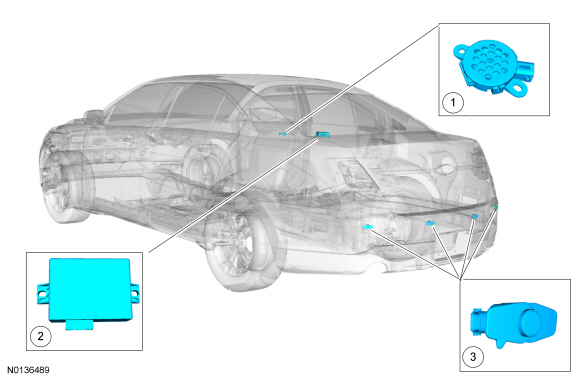
- Parking aid speaker
- PAM
- Parking aid sensors
Overview
The parking aid system sounds a warning to alert the driver of stationary objects near the rear bumper when REVERSE is selected. The rear sensors are activated when REVERSE is selected. The parking aid system assists the driver in detecting certain objects while the vehicle moves slowly in REVERSE at speeds of less than 4.8 kmh (3 mph). The parking aid system may not detect moving objects.
The parking aid system is active when the ignition switch is in the RUN position and the transmission in REVERSE. The parking aid system is disabled if a fault is detected in 1 of the 4 sensors, the parking aid speaker, or the PAM. This is indicated by a parking aid disabled warning message in the message center.
The parking aid system is enabled and disabled through the message center, located in the IPC.
If a MyKey restricted key is in use, the parking aid menu is not available in the message center and cannot be deactivated.
System Operation
System Diagram
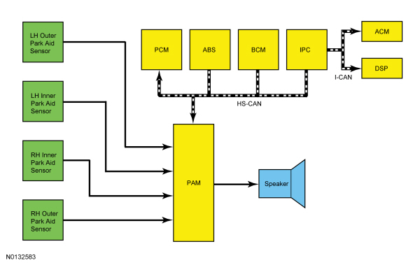
Network Message Chart
Module Network Input Messages - PAM

Module Network Input Messages - IPC

Module Network Input Messages - ACM

Module Network Input Messages - Audio DSP Module with Sony Sound

Parking Aid System Operation
The parking aid system calculates the distance to an object around the rear of the vehicle using 4 ultrasonic sensors. The parking aid sensors detect objects approximately 1,524 mm (60 in) from the rear of the vehicle, 508 mm (20 in) from the rear side of the vehicle, and 304.8 mm (12 in) above the ground.
The PAM calculates the distance to an object within the 170 degree semicircular (azimuth) area around the rear of the vehicle. A variable-rate warning tone is generated from a speaker attached to the PAM.
The PAM can be diagnosed with a scan tool.
Parking Aid Audible Alert
The speaker increases its warning tone rate as the vehicle gets closer to an obstacle. When an object is detected within 304.8 mm (12 in) of the sensors, the warning tone becomes continuous.
When the PAM sounds the parking aid tone, it sends an audio volume cutback message to the IPC which sends a message over the to the ACM. When the ACM receives the message, it reduces the speaker output so the parking aid tone can be heard. If the vehicle is equipped with Sony sound the audio DSP module reduces the speaker output.
Component Description
Parking Aid Sensors
The parking aid sensors are 3-wire type ultrasonic distance detecting sensors.
Parking Aid Module (PAM)
The PAM calculates and reports via audible output the distance between the rear of the vehicle and an object. The PAM requires PMI when replaced.
Parking Aid Speaker
The parking aid speaker is a variable-rate warning tone and is commanded by the PAM.
DIAGNOSIS AND TESTING
Parking Aid
DTC Charts
Diagnostics in this manual assume a certain skill level and knowledge of Ford-specific diagnostic practices. Refer to Diagnostic Methods in Section 100-00 for information about these practices.
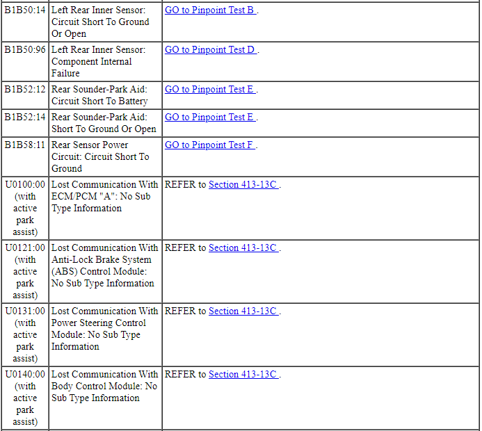
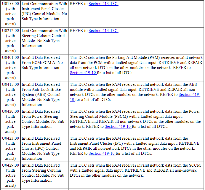
Parking Aid Module (PAM) DTC Chart
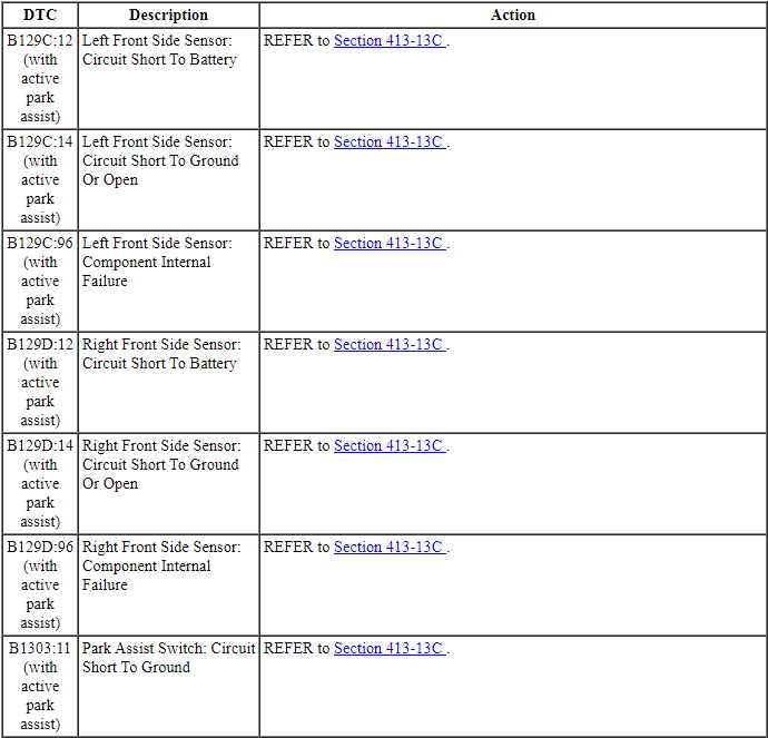
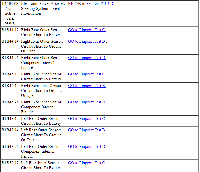

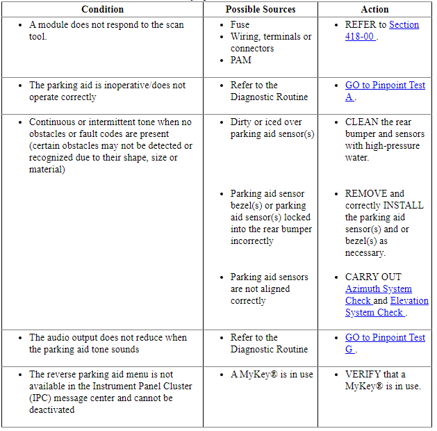
Symptom Chart
Diagnostics in this manual assume a certain skill level and knowledge of Ford-specific diagnostic practices. Refer to Diagnostic Methods in Section 100-00 for information about these practices.
Pinpoint Tests
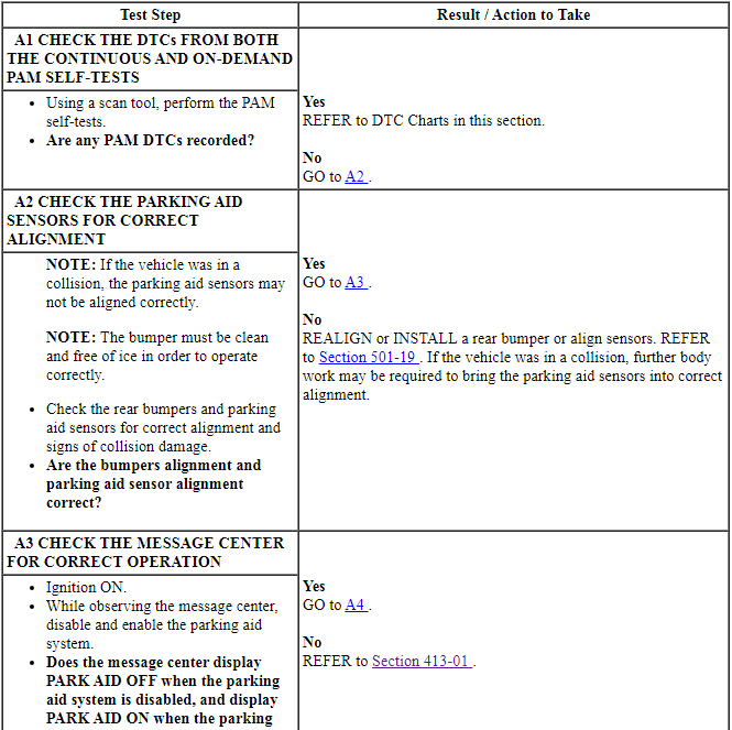
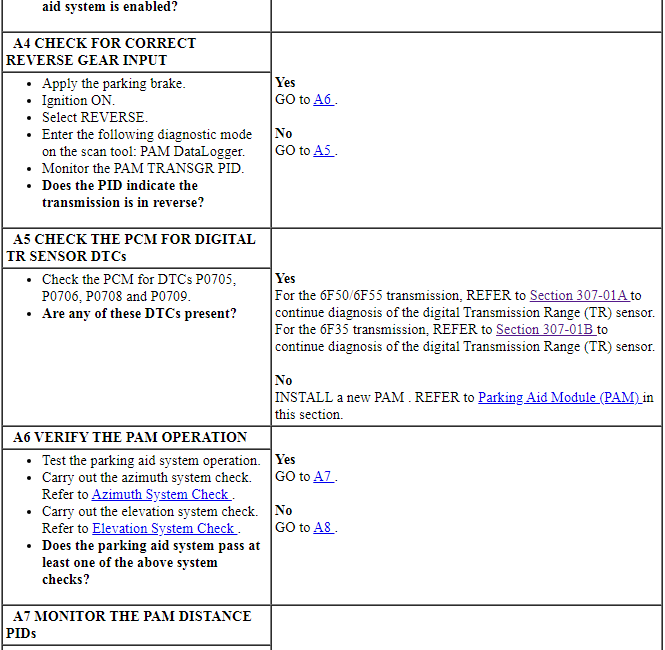
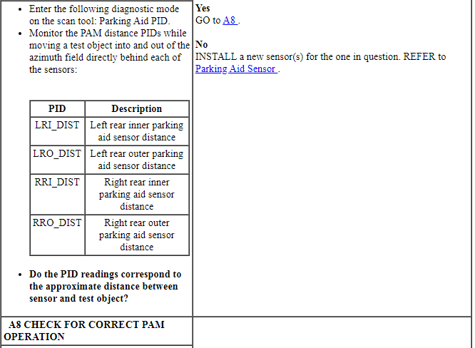
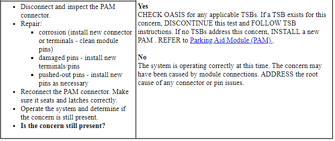
Pinpoint Test A: The Parking Aid Is Inoperative/Does Not Operate Correctly
Diagnostic Overview
Diagnostics in this manual assume a certain skill level and knowledge of Ford-specific diagnostic practices. Refer to Diagnostic Methods in Section 100-00 for information about these practices.
Refer to Wiring Diagrams Cell 131, Parking Aid for schematic and connector information.
Normal Operation and Fault Conditions
REFER to Parking Aid System Operation in Parking Aid.
If a MyKey restricted key is in use, the parking aid menu is not available in the message center and cannot be deactivated.
-
Possible Sources
- Wiring, terminals or connectors
- Parking aid sensor alignment
- Bumper cover
- PAM
PINPOINT TEST A: THE PARKING AID IS INOPERATIVE/DOES NOT OPERATE CORRECTLY
Pinpoint Test B: DTC B1B44:14, B1B46:14, B1B48:14 Or B1B50:14
Diagnostic Overview
Diagnostics in this manual assume a certain skill level and knowledge of Ford-specific diagnostic practices. Refer to Diagnostic Methods in Section 100-00 for information about these practices.
Refer to Wiring Diagrams Cell 131, Parking Aid for schematic and connector information.
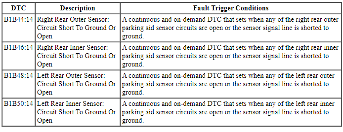
DTC Fault Trigger Conditions
-
Possible Sources
- Wiring, terminals or connectors
- Parking aid sensor
- PAM
Visual Inspection and Diagnostic Pre-checks
Before disconnecting the PAM or the sensors, verify that the connectors are properly seated and latched.
PINPOINT TEST B: DTC B1B44:14, B1B46:14, B1B48:14 OR B1B50:14
NOTICE: Use the correct probe adapter(s) when making measurements. Failure to use the correct probe adapter(s) may damage the connector.
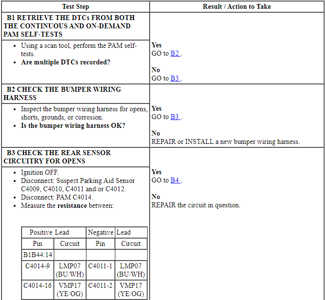
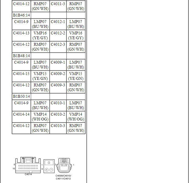
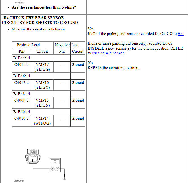
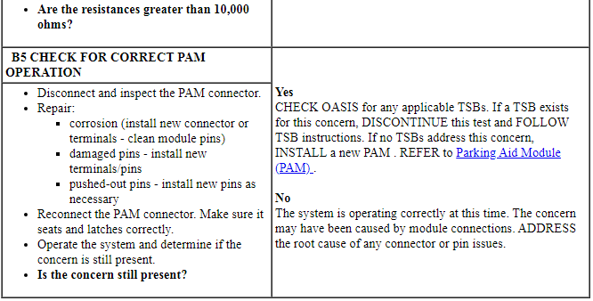
Pinpoint Test C: DTC B1B44:12, B1B46:12, B1B48:12 Or B1B50:12
Diagnostic Overview
Diagnostics in this manual assume a certain skill level and knowledge of Ford-specific diagnostic practices. Refer to Diagnostic Methods in Section 100-00 for information about these practices.
Refer to Wiring Diagrams Cell 131, Parking Aid for schematic and connector information.
Normal Operation and Fault Conditions
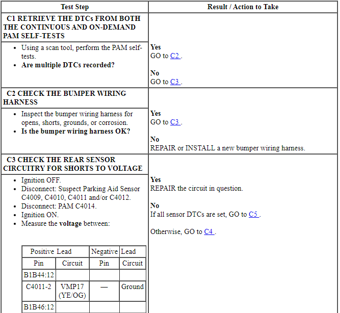
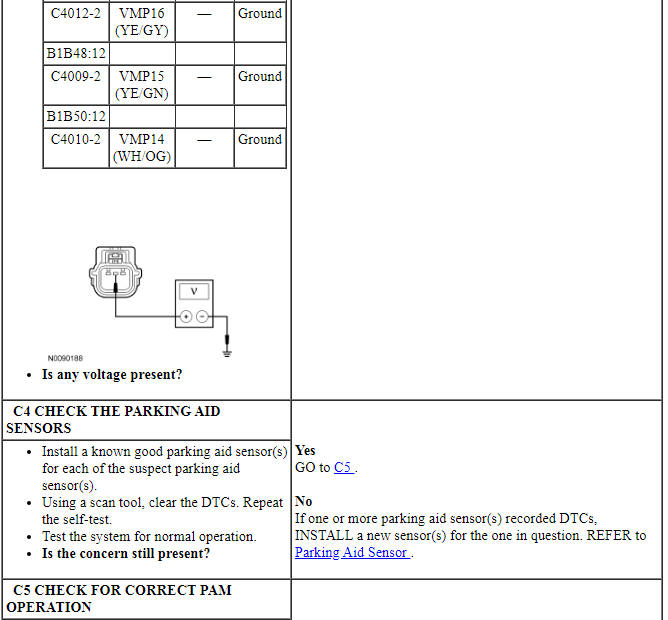
The PAM supplies a reference voltage and signal return to rear parking aid sensors. A fault condition occurs when the PAM detects a short to voltage on the parking aid sensor signal circuit.
DTC Fault Trigger Conditions

-
Possible Sources
- Wiring, terminals or connectors
- Parking aid sensor
- PAM
Visual Inspection and Diagnostic Pre-checks
Before disconnecting the PAM or the sensors, verify that the connectors are properly seated and latched.
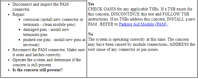
PINPOINT TEST C: DTC B1B44:12, B1B46:12, B1B48:12 OR B1B50:12
NOTICE: Use the correct probe adapter(s) when making measurements. Failure to use the correct probe adapter(s) may damage the connector.
Pinpoint Test D: DTC B1B44:96, B1B46:96, B1B48:96 Or B1B50:96
Diagnostic Overview
Diagnostics in this manual assume a certain skill level and knowledge of Ford-specific diagnostic practices. Refer to Diagnostic Methods in Section 100-00 for information about these practices.
Refer to Wiring Diagrams Cell 131, Parking Aid for schematic and connector information.
Normal Operation and Fault Conditions
REFER to Parking Aid System Operation in Parking Aid.
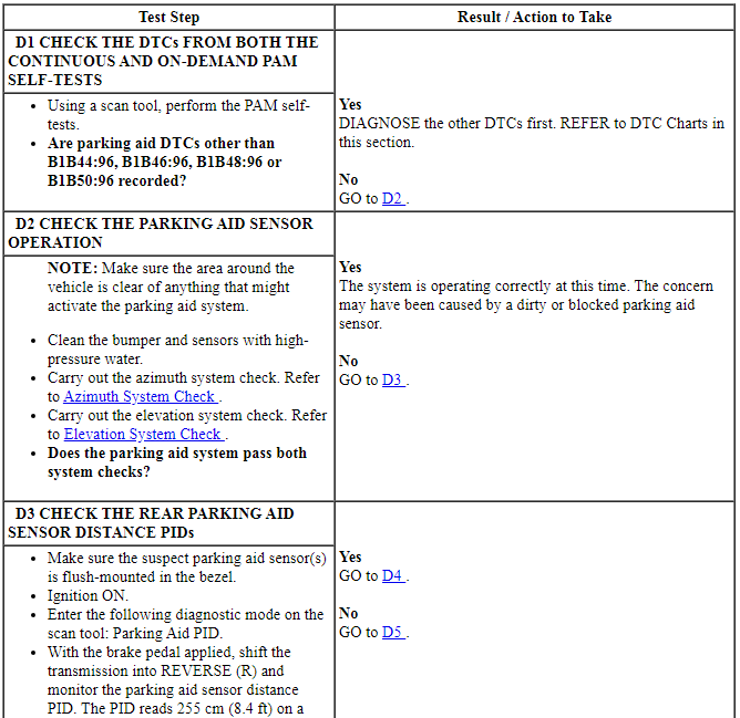
The attenuation time for the rear parking aid sensors is the time required for a sensor to detect the distance to an object expressed in milliseconds (ms). A fault condition occurs when the signal or the attenuation time is out of normal range.
DTC Fault Trigger Conditions

-
Possible Sources
- Wiring, terminals or connectors
- Parking aid sensor
- PAM
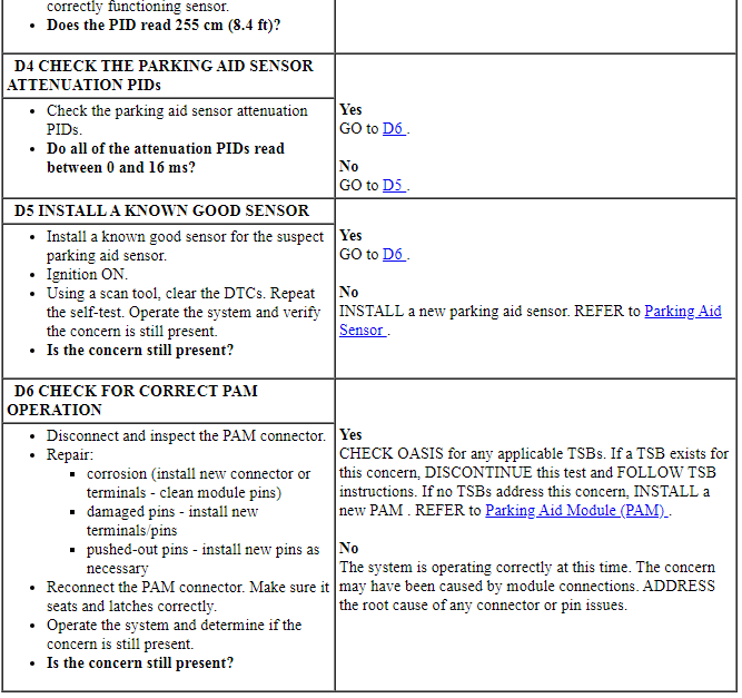
PINPOINT TEST D: DTC B1B44:96, B1B46:96, B1B48:96 OR B1B50:96
Pinpoint Test E: DTC B1B52:12 Or DTC B1B52:14
Diagnostic Overview
Diagnostics in this manual assume a certain skill level and knowledge of Ford-specific diagnostic practices. Refer to Diagnostic Methods in Section 100-00 for information about these practices.
Refer to Wiring Diagrams Cell 131, Parking Aid for schematic and connector information.
DTC Fault Trigger Conditions

-
Possible Sources
- Wiring, terminals or connectors
- Rear parking aid speaker
- PAM
Visual Inspection and Diagnostic Pre-checks
Before disconnecting the PAM or the sensors, verify that the connectors are properly seated and latched.
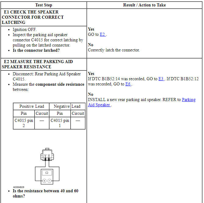
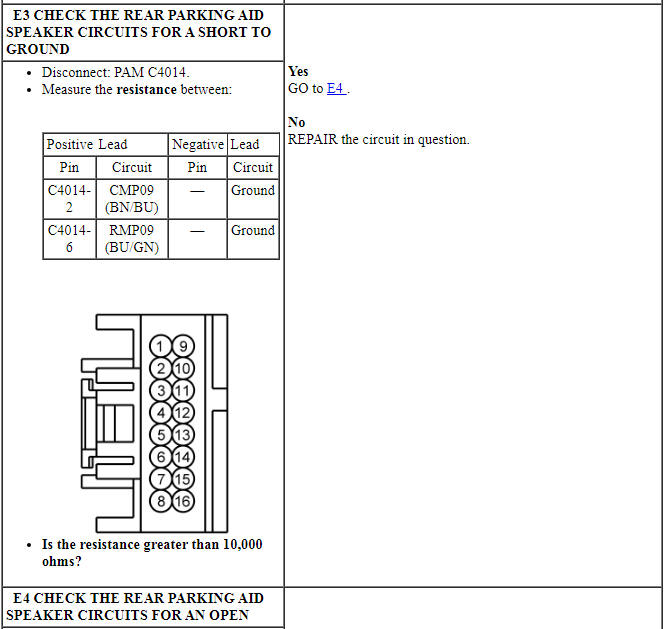
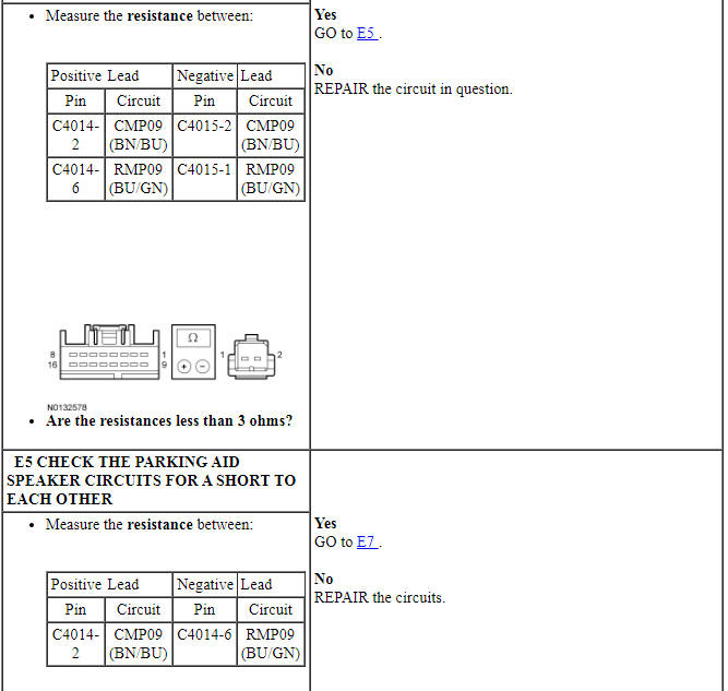
PINPOINT TEST E: DTC B1B52:12 OR DTC B1B52:14
NOTICE: Use the correct probe adapter(s) when making measurements. Failure to use the correct probe adapter(s) may damage the connector.
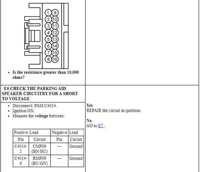
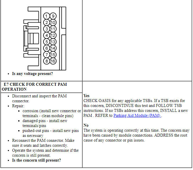
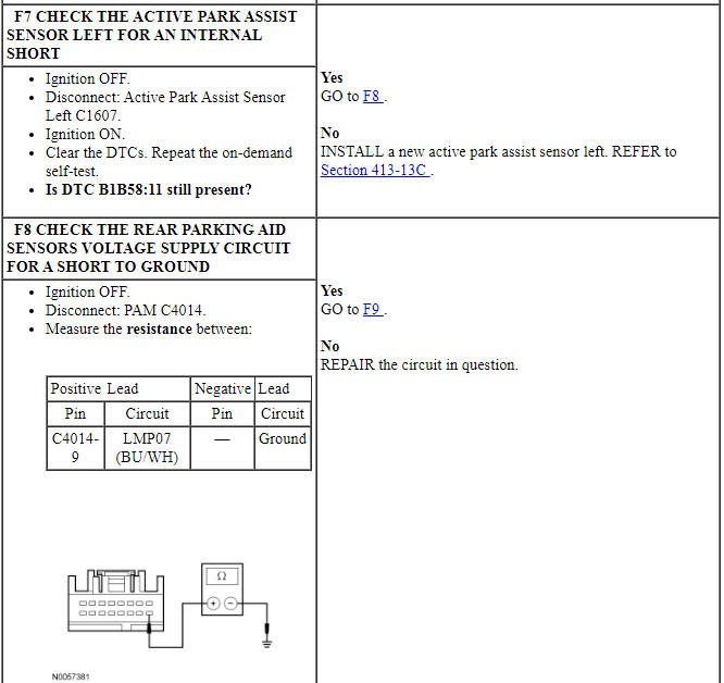
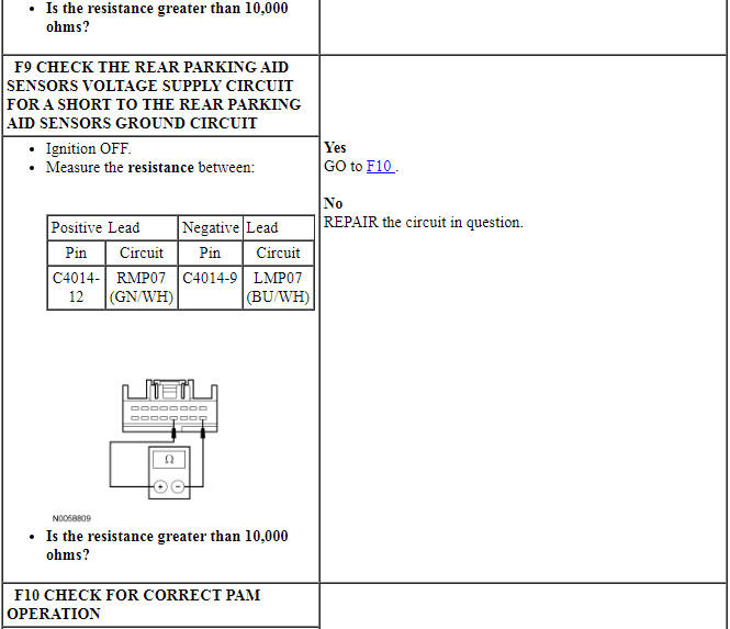
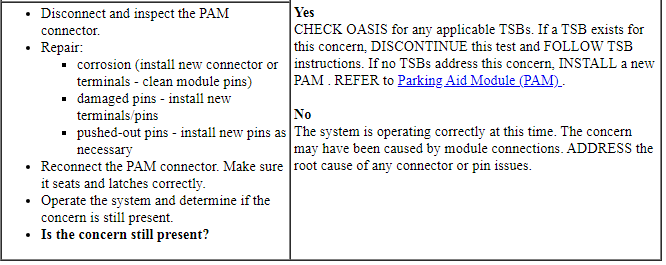
Pinpoint Test F: DTC B1B58:11
Diagnostic Overview
Diagnostics in this manual assume a certain skill level and knowledge of Ford-specific diagnostic practices. Refer to Diagnostic Methods in Section 100-00 for information about these practices.
Refer to Wiring Diagrams Cell 131, Parking Aid for schematic and connector information.
DTC Fault Trigger Conditions

-
Possible Sources
- Wiring, terminals or connectors
- Parking aid sensor
- PAM
Visual Inspection and Diagnostic Pre-checks
Before disconnecting the PAM or the sensors, verify that the connectors are properly seated and latched.
PINPOINT TEST F: DTC B1B58:11
NOTICE: Use the correct probe adapter(s) when making measurements. Failure to use the correct probe adapter(s) may damage the connector.
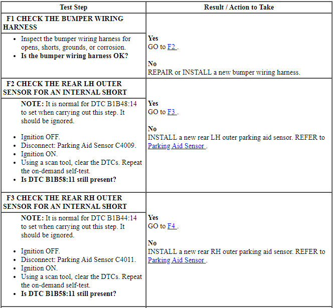
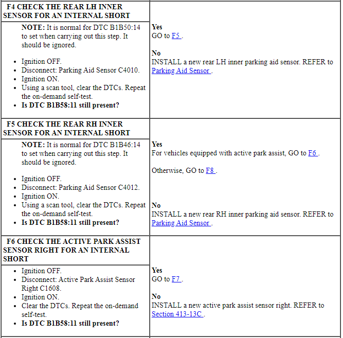
Pinpoint Test G: The Audio Output Does Not Reduce When The Parking Aid Tone Sounds
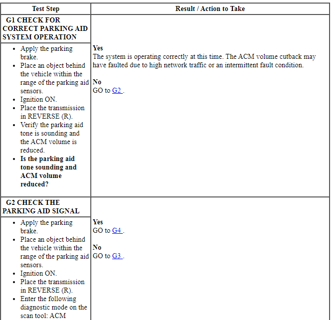
Diagnostic Overview
Diagnostics in this manual assume a certain skill level and knowledge of Ford-specific diagnostic practices. Refer to Diagnostic Methods in Section 100-00 for information about these practices.
Normal Operation and Fault Conditions
REFER to Parking Aid Audible Alert in Parking Aid.
-
Possible Sources
- Wiring, terminals or connectors
- PAM
- ACM
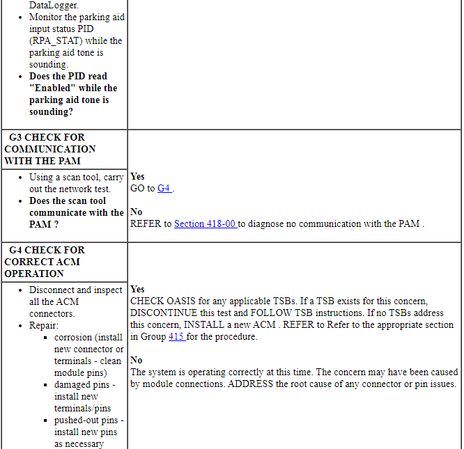
PINPOINT TEST G: THE AUDIO OUTPUT DOES NOT REDUCE WHEN THE PARKING AID TONE SOUNDS

GENERAL PROCEDURES
Azimuth System Check
Minimum Detectable Object Locations
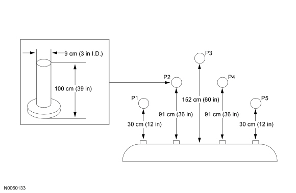
- NOTE: The object used in this system check can be fabricated
using a 9 cm diameter (3 in I.D.) pipe, 100 cm (39 in) in length (available
as Polyvinyl Chloride (PVC) pipe, or similar from a hardware or plumbing
supply.
NOTE: The following system check should be carried out with the vehicle on a level surface.
NOTE: The parking aid system defaults to on when the ignition key is cycled from the OFF position to the ON position.
Turn the ignition switch to the ON position, engine off.
- Apply the parking brake.
- Place the gear shift in REVERSE (R).
- Verify that the Parking Aid Module (PAM) detects the objects when placed
in the 5 specified locations (P1, P2, P3, P4 and P5).
- The speaker should beep slowly when objects are detected on the outer edges of the detection zone, and increase as the object is moved closer to the vehicle. When the object is within 25 cm (10 in) of the rear bumper, the sounder should sound continuously.
- If the PAM does not detect the object above, refer to Parking Aid in the Diagnosis and Testing portion of this section.
Elevation System Check
- Check the parking aid system to make sure the system does not see signals caused by ground reflections.
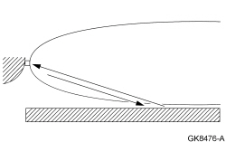
- The following system check should be carried out with the vehicle on a 4.6 m (15 ft) wide by 3.0 m (10 ft) deep smooth concrete surface, free of all obstacles. The area should also be free of noise from fans and pneumatic tools.
- Turn the ignition switch to the ON position, engine off.
- Apply the parking brake.
- Place the gear shift in REVERSE (R).
- NOTE: No audible warning tones should be heard. If audible
warning tones are heard, check to make sure the bumper is installed
correctly and not tilted downward so that the sensor is pointing towards the
ground.
Verify that no audible warning tones are heard.
- If the audible warning tone is heard, refer to Parking Aid in the Diagnosis and Testing portion of this section.
REMOVAL AND INSTALLATION
Parking Aid Module (PAM)

Removal and Installation
- NOTE: Module configuration is only required if a new Parking Aid
Module (PAM) is being installed.
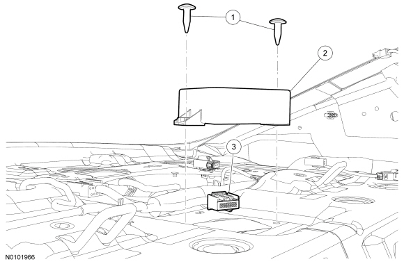
Upload the PAM configuration information to the scan tool. For additional information, refer to Programmable Module Installation (PMI) in Section 418-01.
- Remove the package tray trim panel. For additional information, refer to Section 501-05.
- Remove the 2 pin-type retainers.
- Disconnect the electrical connector.
- Remove the PAM.
- To install, reverse the removal procedure.
- Download the configuration information to the PAM. For additional information, refer to PMI in Section 418-01.
Parking Aid Speaker
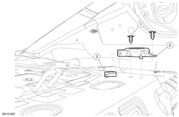

Removal and Installation
- Remove the parcel shelf. For additional information, refer to Section 501-05.
- Remove the 2 push pins and the parking aid speaker.
- Disconnect the electrical connector.
- To install, reverse the removal procedure.
Parking Aid Sensor
Removal
- With the vehicle in NEUTRAL, position it on a hoist. For additional information, refer to Section 100-02.
- Remove the rear bumper cover. For additional information, refer to Section 501-19.
- NOTE: Gently pry the retaining tabs on the parking aid sensor bezels to release the sensor(s).
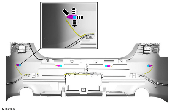
Installation
- To install, reverse the removal procedure.
- Carry out the azimuth and elevation system check. For additional information, refer to Azimuth System Check and Elevation System Check.
 Horn
Horn
SPECIFICATIONS
Torque Specifications
DESCRIPTION AND OPERATION
Horn
Component Location
Overview
The horn emits an audible tone when the driver air bag module is pressed. The
horn output is control ...
 Parking Aid - Visual
SPECIFICATIONS
General Specifications
DESCRIPTION AND OPERATION
Parking Aid
Component Location
Overview
The video camera system visually aids the driver while reversing or reverse
parking the vehi ...
Other materials:
Jump-starting the vehicle
WARNING: The gases around the battery can explode if exposed
to flames, sparks, or lit cigarettes. An explosion could result in
injury or vehicle damage.
WARNING: Batteries contain sulfuric acid which can burn skin,
eyes and clothing, if contacted.
Do not attempt to push-start your automatic tr ...
Steering Column
SPECIFICATIONS
Torque Specifications
DESCRIPTION AND OPERATION
Steering Column
The steering column system consists of the following components:
Intermediate shaft
Steering column
SCCM (if equipped)
Steering column switches
Steering column tilt motor (if equipped)
Steering wheel
Selecto ...
Diagnosis and Testing
Information and Entertainment System
Special Tool(s)
Preliminary Inspection
Before diagnosing or repairing the audio system, verify the audio system
module(s) pass the network test.
DTC Chart(s)
NOTE: For SYNC related concerns, REFER to the SYNC Symptom Chart before
connecting the scan to ...
