SPECIFICATIONS
Material
Torque Specifications
DESCRIPTION AND OPERATION
Fuel Charging and Controls
Component Locations
WARNING: Do not smoke, carry lighted tobacco or have an open flame of any type when working on or near any fuel-related component. Highly flammable mixtures are always present and may be ignited. Failure to follow these instructions may result in serious personal injury.
NOTICE: Handle the fuel injectors and fuel rail with extreme care to prevent damage to the fuel inlet of the fuel rail, fuel injector sealing areas, and sensitive fuel-metering orifices.
Fuel Charging and Controls
FPCM
System Operation
REFER to the PC/ED manual section 1 Description and Operation.
Component Description
REFER to the PC/ED manual section 1 Description and Operation.
DIAGNOSIS AND TESTING
Fuel Charging and Controls
For PCM DTCs, REFER to Section 303-14, PCM DTC Chart. For driveability symptoms without DTCs, refer to the Powertrain Control/Emissions Diagnosis (PC/ED) manual, section 3 Symptom Charts.
REMOVAL AND INSTALLATIONThrottle Body
Removal and Installation
NOTE: Removal steps in this procedure may contain installation details.
- Remove the Air Cleaner (ACL) outlet pipe. For additional information, refer to Section 303-12.
-
- Tighten to 10 Nm (89 lb-in).
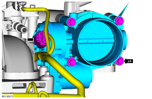
- NOTE: Make sure that a new TB gasket is installed.
- Discard the specified component. Follow local disposal regulations.
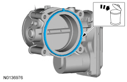
- To install, reverse the removal procedure.
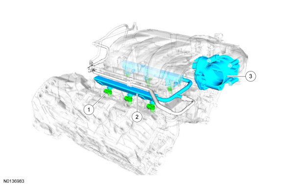
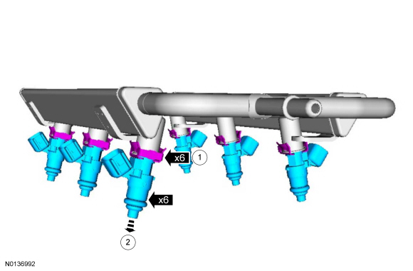
Fuel Injectors
Removal and Installation
- The fuel injectors are serviced with the fuel rail. For additional information, refer to Fuel Rail in this section.
Fuel Rail
Material
Removal and Installation
WARNING: Do not smoke, carry lighted tobacco or have an open flame of any type when working on or near any fuel-related component. Highly flammable mixtures are always present and may be ignited. Failure to follow these instructions may result in serious personal injury.
WARNING: Before working on or disconnecting any of the fuel tubes or fuel system components, relieve the fuel system pressure to prevent accidental spraying of fuel. Fuel in the fuel system remains under high pressure, even when the engine is not running. Failure to follow this instruction may result in serious personal injury.
WARNING: Clean all fuel residue from the engine compartment. If not removed, fuel residue may ignite when the engine is returned to operation. Failure to follow this instruction may result in serious personal injury.
WARNING: Always disconnect the battery ground cable at the battery when working on an evaporative emission (EVAP) system or fuel-related component. Highly flammable mixtures are always present and may be ignited. Failure to follow these instructions may result in serious personal injury.
WARNING: Do not carry personal electronic devices such as cell phones, pagers or audio equipment of any type when working on or near any fuel-related component. Highly flammable mixtures are always present and may be ignited. Failure to follow these instructions may result in serious personal injury.
NOTE: Removal steps in this procedure may contain installation details.
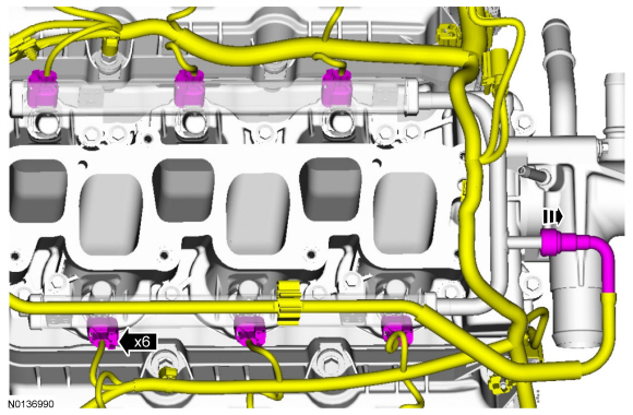
- Release the fuel system pressure. For additional information, refer to Section 310-00.
- Disconnect the battery ground cable. For additional information, refer to Section 414-01.
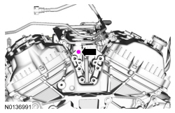
- Remove the upper intake manifold. For additional information, refer to Section 303-01A.
-
- Tighten to 10 Nm (89 lb-in).
- For additional information, refer to Section 310-00.
-
- Tighten to 10 Nm (89 lb-in).
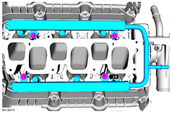
- NOTE: Make sure that a new upper and lower fuel injector O-ring
seals are installed.
Discard the specified component. Follow local disposal regulations.
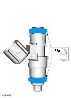
- NOTICE: Use O-ring seals that are made of special
fuel-resistant material. The use of ordinary O-rings seals can cause the
fuel system to leak. Do not reuse the O-ring seals.
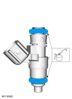
NOTE: The upper and lower fuel injector O-ring seals are similar in appearance but are not interchangeable.
NOTE: Install new fuel injector O-ring seals and lubricate them with clean engine oil.
Apply the specified lubricant to the specified component.
- To install, reverse the removal procedure.
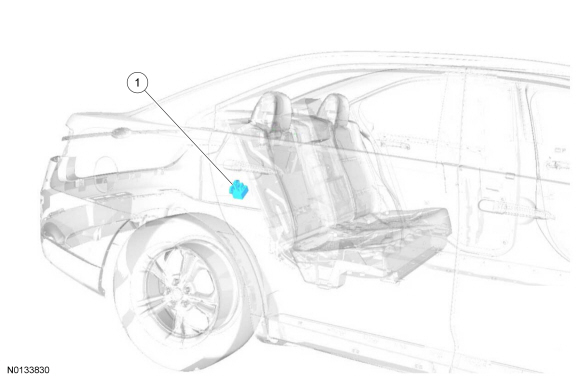
Fuel Pump Control Module
Removal and Installation
NOTE: Removal steps in this procedure may contain installation details.
- Fold the RR seat backrest down.
- NOTICE: Do not overtighten the fasteners or damage to the
module will occur.
Tighten to 5 Nm (44 lb-in).
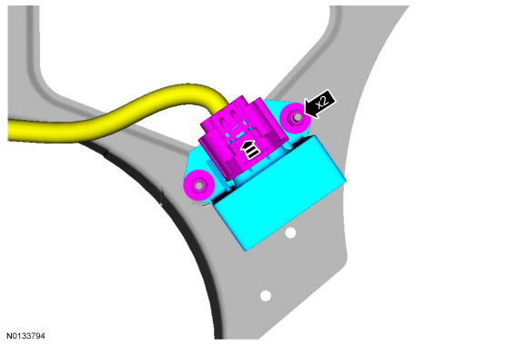
- To install, reverse the removal procedure.
 Removal and Installation
Block Heater - 2.0L GTDI
Removal
NOTE: Removal steps in this procedure may contain installation
details.
Drain the cooling system. For additional information, refer to Cooling
System Dr ...
 Fuel Charging and Controls - 3.5L GTDI
SPECIFICATIONS
Material
Torque Specifications
a Refer to the procedure in this section.
DESCRIPTION AND OPERATION
Fuel Charging and Controls
3.5L Gasoline Turbocharged Direct Injection (GTDI)
W ...
Other materials:
Specifications, Description and Operation, General Procedures
SPECIFICATIONS
Material
General Specifications
Torque Specifications
a Tighten to 10 Nm (89 lb-in) plus an additional 720 degrees.
b Tighten to 16 Nm (142 lb-in) plus an additional 180 degrees.
c Refer to the procedure in this section.
d Tighten to 5 Nm (44 lb-in) plus ...
Steering System
DESCRIPTION AND OPERATION
Steering System
Electronic Power Assist Steering (EPAS) System
The Electronic Power Assist Steering (EPAS) system consists of the following
components:
Power Steering Control Module (PSCM) - the PSCM controls the functions
of the EPAS system and com ...
Data recording
Service Data Recording
Service data recorders in your vehicle are capable of collecting and
storing diagnostic information about your vehicle. This potentially
includes information about the performance or status of various systems
and modules in the vehicle, such as engine, throttle, steering o ...
