DESCRIPTION AND OPERATION
Anti-Theft
Overview
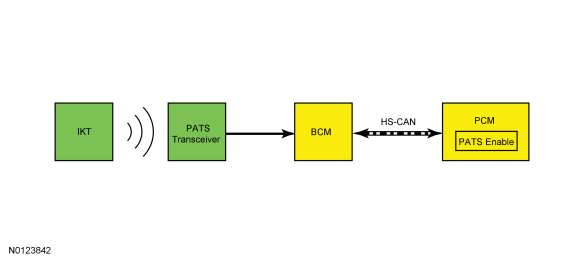
PATS deters the vehicle from theft by preventing the engine from starting unless a programmed PATS key is in the ignition. PATS does not disable an already running engine.
System Operation
System Diagram
Network Message Chart
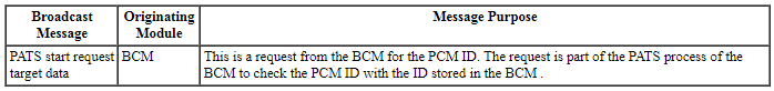
PCM Network Input Messages
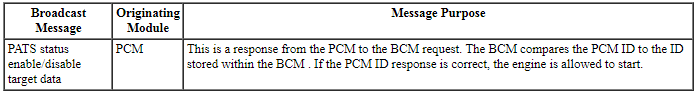
BCM Network Input Messages
Passive Anti-Theft System (PATS)
The PATS function is controlled by the BCM. There are 2 main checks that PATS performs before allowing the engine to start. If either of these checks fail, PATS does not allow the engine to start and STARTING SYSTEM FAULT displays in the message center. These 2 checks are the BCM verifying the PCM identification to make sure it matches the PCM identification stored in memory and to verify that a programmed key was used to change the ignition to RUN or START.
The first check is initiated by the BCM waking up the PCM by supplying voltage on the wakeup control circuit. The BCM only activates the wakeup circuit 5 times. After that, the wakeup circuit remains off until the ignition is cycled to RUN. The BCM activates the wakeup control circuit when any of the following occur:
- The driver door is opened
- A remote start request is received (if equipped with factory remote start)
- The brake pedal is applied
- A key is inserted into the ignition key cylinder
- The ignition transitions to RUN or START
Once the PCM is awake, the BCM sends the PCM a challenge message over the HS-CAN. When the PCM receives the challenge message, it generates a response and sends it back to the BCM. If the response from the PCM does not match the response in the BCM memory, this first check fails and the engine does not start.
Once the PCM identification has been verified, PATS performs the second check to make sure a programmed key is in the ignition key cylinder. When the BCM determines the ignition changes to RUN or START, it generates a challenge message. It sends the challenge message to the PATS transceiver on the transmit (TX) circuit. The transceiver in turn reads the key and generates a response message that is sent back to the BCM on the receive (RX) circuit. If the message received from the transceiver does not match a key stored in the BCM memory, the engine does not start.
If both the PCM identification and key verification pass, PATS allows the engine to start. PATS cannot disable or stall an engine that has already been started.
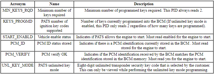
PATS PIDs
In conjunction with DTCs, the PATS PIDs are a useful tool when diagnosing PATS concerns.
BCM Module PID Chart
Unlimited Key Mode
PATS contains a feature called unlimited key mode. This feature allows a customer to program more than 8 keys to their vehicle, if requested. Each vehicle in unlimited key mode is set up with a special unlimited transponder security key code. This allows all of the customer vehicles to share the same mechanically cut keys. For an individual customer, any randomly selected security key that has been previously mechanically cut and electronically programmed to the vehicle is acceptable. To enable/change the unlimited key mode, refer to Key Programming - Unlimited Key Mode.
When in the unlimited key mode, the KEYS_PROGMD PID in the BCM always reads 2, no matter how many keys are programmed to the vehicle (after the first 2 keys have been programmed to the vehicle).
Component Description
Integrated Keyhead Transmitter (IKT)
NOTE: The IKTs must have SA stamped on the keyblade. Conventional PATS keys must have HA or SA stamped on the keyblade.
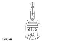
The IKT incorporates both the PATS functions and the RKE transmitter functions in a single device.
During key programming procedures, the PATS and RKE transmitter of an IKT are both programmed into the BCM. Conventional PATS keys can also be programmed to the vehicle if requested by the customer.
Up to a maximum of 4 IKTs can be programmed. If more than 4 IKTs are programmed, INT KEY COULD NOT PROGRAM displays in the message center during the key programming procedure and the RKE functions of that IKT are inoperative.
Passive Anti-Theft System (PATS) Transceiver
The PATS transceiver reads any key that is placed in the ignition. When the ignition changes to ON or START, the BCM activates the PATS transceiver. Once the transceiver is activated, it in turn activates the key in the ignition and receives the key data. Once the transceiver receives the key data, it sends the data to the BCM.
DIAGNOSIS AND TESTING
Anti-Theft
DTC Charts
Diagnostics in this manual assume a certain skill level and knowledge of Ford-specific diagnostic practices. Refer to Diagnostic Methods in Section 100-00 for information about these practices.
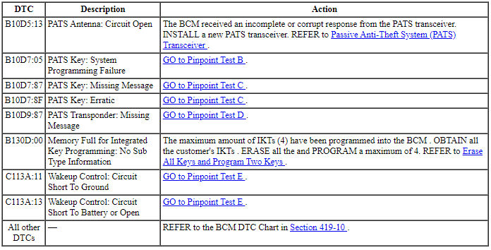
BCM DTC Chart
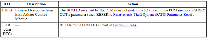
PCM DTC Chart
Symptom Chart
Diagnostics in this manual assume a certain skill level and knowledge of Ford-specific diagnostic practices. Refer to Diagnostic Methods in Section 100-00 for information about these practices.
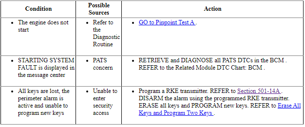
Symptom Chart: Passive Anti-Theft System (PATS)
Pinpoint Tests
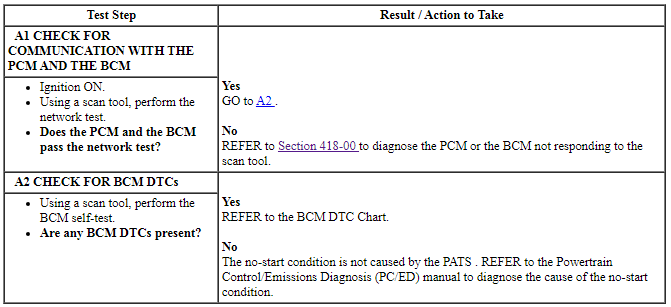
Pinpoint Test A: The Engine Does Not Start
Diagnostic Overview
Diagnostics in this manual assume a certain skill level and knowledge of Ford-specific diagnostic practices. Refer to Diagnostic Methods in Section 100-00 for information about these practices.
Normal Operation and Fault Conditions
Refer to System Operation - Passive Anti-Theft System (PATS) in Anti-Theft.
Refer to Component Description - Integrated Keyhead Transmitter (IKT) in Anti-Theft.
Refer to Component Description - Passive Anti-Theft System (PATS) Transceiver in Anti-Theft.
-
Possible Sources:
- Driveability system concern
- Starting system concern
- PATS concern
PINPOINT TEST A: THE ENGINE DOES NOT START
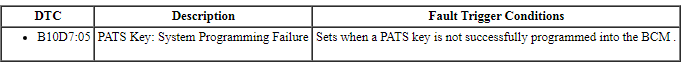
Pinpoint Test B: B10D7:05
Diagnostic Overview
Diagnostics in this manual assume a certain skill level and knowledge of Ford-specific diagnostic practices. Refer to Diagnostic Methods in Section 100-00 for information about these practices.
Normal Operation and Fault Conditions
When the BCM enters a key programming state, it activates the transceiver to read the key in the ignition key cylinder. If a valid PATS key is used and there are no concerns with the PATS, the key is programmed into the BCM memory.
BCM DTC Fault Trigger Conditions
-
Possible Sources:
- PATS key not programmed
Visual Inspection and Diagnostic Pre-checks
- Inspect the PATS key for damage.
- Verify the correct key is used.
PINPOINT TEST B: B10D7:05
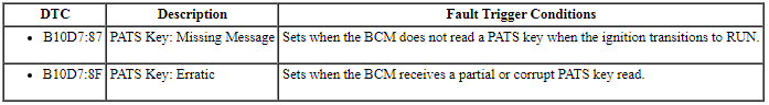
Pinpoint Test C: B10D7:87 or B10D7:8F
Diagnostic Overview
Diagnostics in this manual assume a certain skill level and knowledge of Ford-specific diagnostic practices. Refer to Diagnostic Methods in Section 100-00 for information about these practices.
Normal Operation and Fault Conditions
When the ignition transitions to RUN or START, the BCM activates the transceiver to read the key in the ignition key cylinder. If the BCM does not receive a PATS key code or if the code is invalid, the PATS does not allow the engine does not start.
BCM DTC Fault Trigger Conditions
-
Possible Sources:
- PATS key
- PATS transceiver
Visual Inspection and Diagnostic Pre-checks
- Inspect the PATS key for damage.
- Verify the correct key is used.
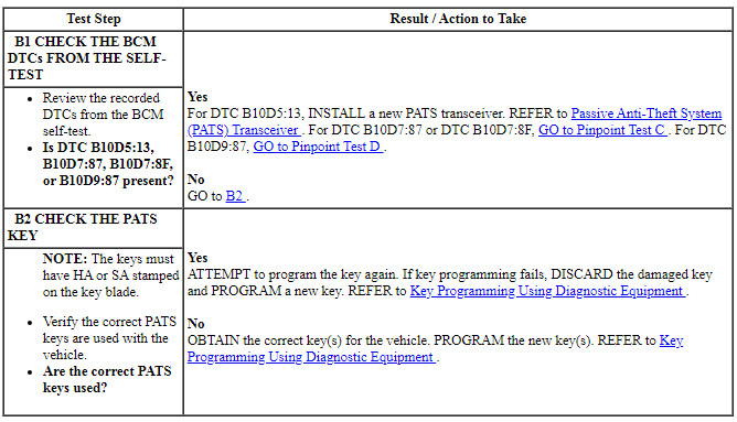
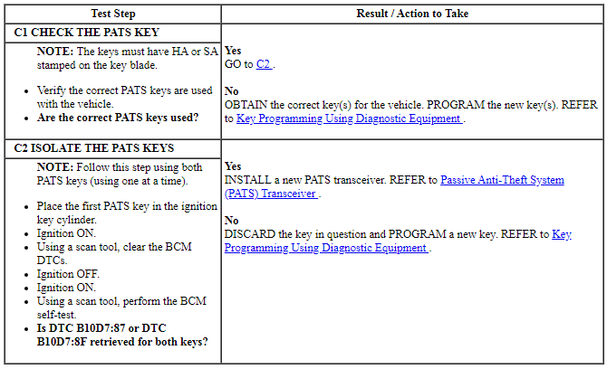
PINPOINT TEST C: B10D7:87 OR B10D7:8F
NOTE: This pinpoint test requires a second programmed PATS keys. If only one key is available, a second programmed PATS key must be obtained.
Pinpoint Test D: B10D9:87
Diagnostic Overview
Diagnostics in this manual assume a certain skill level and knowledge of Ford-specific diagnostic practices. Refer to Diagnostic Methods in Section 100-00 for information about these practices.
Refer to Wiring Diagrams Cell 112, Passive Anti-Theft System for schematic and connector information.
Normal Operation and Fault Conditions
The BCM supplies voltage to the PATS transceiver. When the ignition changes to RUN or START, the BCM initiates the key interrogation sequence. The BCM starts the interrogation sequence by generating a signal and sending that signal to the transceiver on the transmit (TX) circuit. When the transceiver receives the signal from the BCM, it reads the PATS key and generates a challenge response to the BCM signal. The transceiver sends the challenge response back to the BCM on the receive (RX) circuit.
BCM DTC Fault Trigger Conditions

-
Possible Sources:
- Fuse
- Wiring, terminals or connectors
- PATS transceiver
- BCM
Visual Inspection and Diagnostic Pre-checks
- Verify the BCM fuse 18 (10A) is OK.
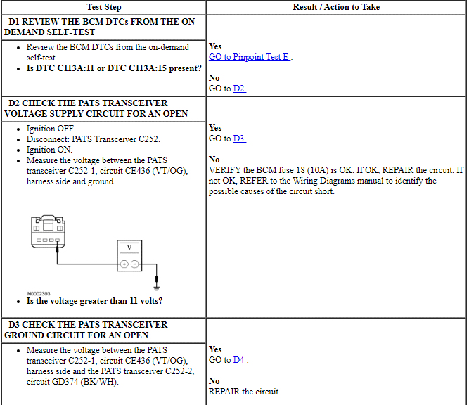
PINPOINT TEST D: B10D9:87
NOTICE: Use the correct probe adapter(s) when making measurements. Failure to use the correct probe adapter(s) may damage the connector.
Pinpoint Test E: C113A:11 or C113A:15
Diagnostic Overview
Diagnostics in this manual assume a certain skill level and knowledge of Ford-specific diagnostic practices. Refer to Diagnostic Methods in Section 100-00 for information about these practices.
Refer to Wiring Diagrams Cell 112, Passive Anti-Theft System for schematic and connector information.
Normal Operation and Fault Conditions
The wakeup control circuit wakes up the PCM prior to engine cranking. The PCM needs to wake up prior to a crank request so that it has time to go through its initialization. The wakeup control circuit also powers the PATS transceiver. The wakeup control circuit is controlled by the BCM. The wakeup control circuit is FET protected.
The BCM activates the wakeup control circuit when:
- the driver door is opened,
- a remote start request is received (if equipped with factory remote start),
- the brake pedal is applied,
- a key is inserted into the ignition key cylinder, or
- the ignition is in RUN or START.
BCM DTC Fault Trigger Conditions
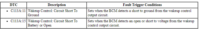
-
Possible Sources:
- Wiring, terminals or connectors
- PATS transceiver
- BCM
- PCM
Visual Inspection and Diagnostic Pre-checks
- Verify the BCM fuse 18 (10A) is OK.
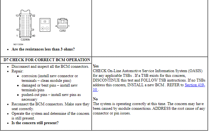
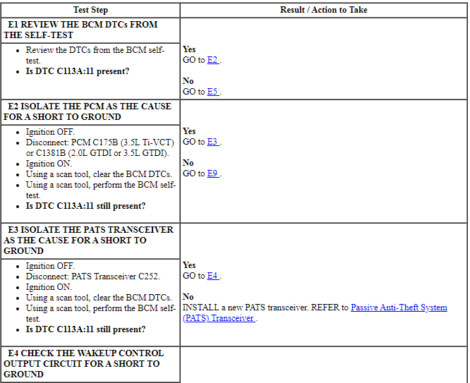
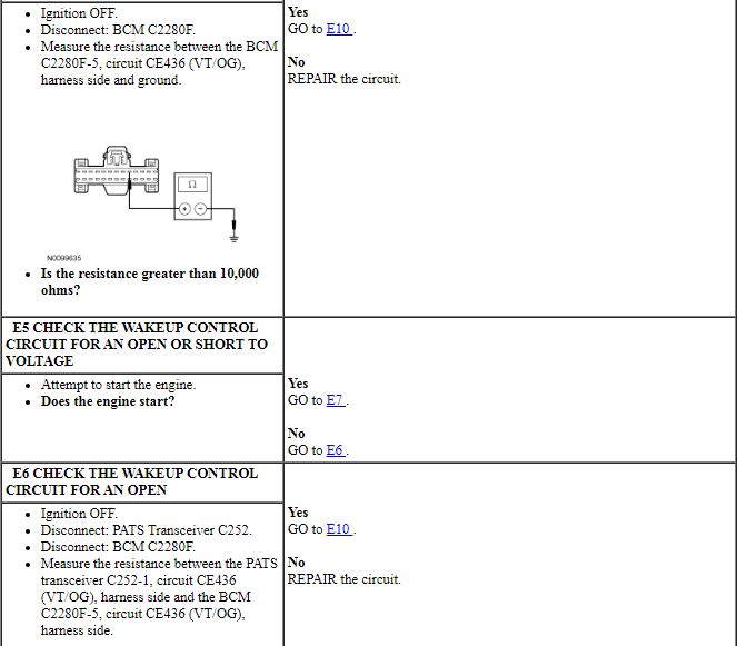
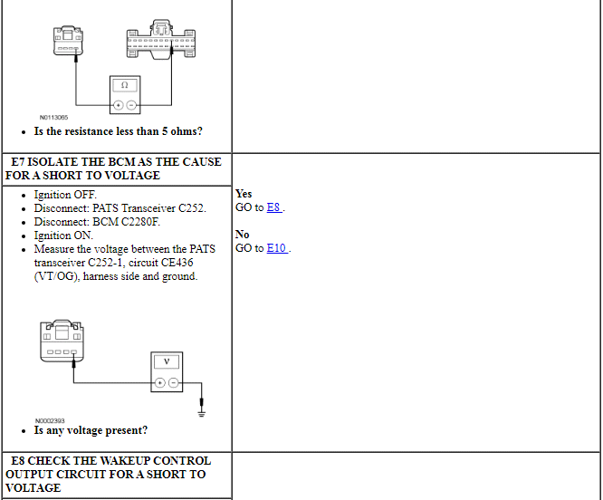
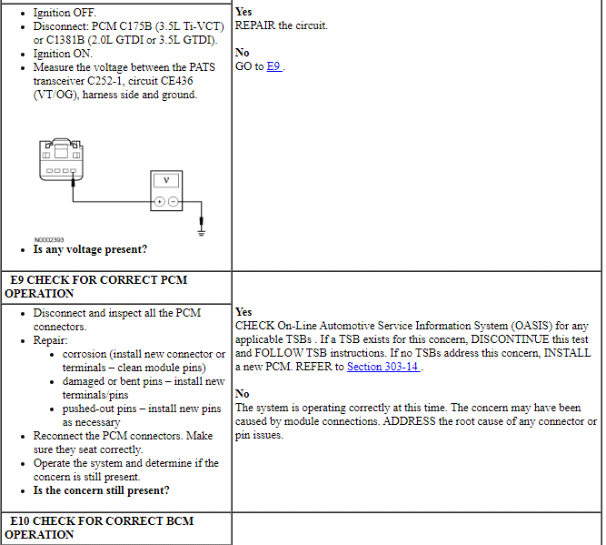
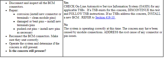
PINPOINT TEST E: C113A:11 OR C113A:15
GENERAL PROCEDURES
Enable or Disable Spare Key Programming
NOTE: This procedure provides the capability to enable/disable the normal customer spare key programming procedure detailed in the Owner's Literature and the Key Programming Using Two Programmed Keys procedure. If spare key programming is disabled, spare keys can only be programmed by using the scan tool. REFER to Key Programming Using Diagnostic Equipment.
- Turn the ignition key cylinder from OFF to RUN.
- From the scan tool, enter TOOLBOX. Select Body>Security>PATS Functions and follow the IDS on-screen instructions to enter PATS security access.
- From the scan tool menu, select "Customer Spare Key Programming Enable" or "Customer Spare Key Programming Disable" and follow the IDS on-screen instructions.
Erase All Keys and Program Two Keys
General Procedure
NOTE: This procedure erases all programmed ignition keys from the vehicle memory. The vehicle cannot start until a minimum of 2 keys are programmed into the BCM-B.
NOTE: Two PATS keys with the correct mechanical cut must be available to carry out this procedure.
NOTE: This procedure erases all MyKey features on all of the keys that are programmed to the vehicle. All of the keys then operate as normal (admin) keys with no restrictions.
- Turn the key from the OFF position to the ON position.
- From the scan tool, enter TOOLBOX. Select Body>Security>PATS Functions and follow the IDS on-screen instructions to enter PATS security access.
- From the scan tool menu, select "Ignition Key Code Erase" and follow the IDS on-screen instructions until the key erase procedure completes. The scan tool then instructs you to program 2 keys to complete the process.
- Turn the key to the OFF position and disconnect the scan tool (the key does not need to be removed from the ignition at this time).
- NOTE: The doors lock and then unlock to confirm that each IKT is
programmed.
Turn the first PATS key to the RUN position for a minimum of 6 seconds.
- Turn the first PATS key to the OFF position and remove the key from the ignition.
- Insert the second PATS key into the ignition and turn the key to the RUN position for a minimum of 6 seconds.
- The engine should now start with both PATS keys.
- If it is desired to program additional keys, refer to Key Programming
Using Two Programmed Keys for each additional key that needs to be
programmed.
- A total of 8 PATS keys can be programmed into the BCM-B. Of those 8 keys, a maximum of 4 IKTs can be programmed.
Key Programming - Unlimited Key Mode
Enable
NOTE: When in the unlimited key mode, the KEYS_PROGMD PID in the BCM always reads 2, regardless of how many keys are programmed to the vehicle (after the first 2 keys have been programmed to the vehicle).
NOTE: If the BCM PID UNL_KEY_ID is not available, unlimited key mode is turned on and must be turned off before viewing the stored code. At this time, unlimited keys may be programmed to the vehicle. To view/disable/change the stored code, follow the procedure below for disabling the unlimited key mode.
- The customer must choose an 8-digit number (except for 00000000, 00000001, or FFFFFFFF) to be programmed to all of their vehicles or to all of the keys for one vehicle. Valid digits are 0-9 and the letters A-F.
- From the scan tool, enter TOOLBOX. Select Body>Security>PATS Functions and follow the IDS on-screen instructions to enter PATS security access.
- Once in security access, select "unlimited key mode ON" and follow the IDS on-screen instructions.
- Select "program unlimited key code" and follow the IDS on-screen instructions. Enter the 8-digit code chosen by the customer in step 1 of this procedure and follow the IDS on-screen instructions.
- Select "Ignition Key Code Erase" and follow the IDS on-screen instructions.
- Turn the key to OFF and disconnect the scan tool (the key does not need to be removed from the ignition at this time).
- Turn the first PATS key to RUN for a minimum of 3 seconds.
- Turn the first PATS key to OFF and remove the key from the ignition key cylinder.
- Insert the second PATS key into the ignition key cylinder and turn the ignition key cylinder to RUN for a minimum of 3 seconds.
- The engine should now start with either PATS key.
- If it is desired to program additional key(s), REFER to Key Programming Using Two Programmed Keys.
Disable
- From the scan tool, enter TOOLBOX. Select Body>Security>PATS Functions and follow the IDS on-screen instructions to enter PATS security access.
- Select "unlimited key mode OFF" and follow the IDS on-screen instructions.
- Select "Ignition Key Code Erase" and follow the IDS on-screen instructions.
- Turn the key to OFF and disconnect the scan tool (the key does not need to be removed at this time).
- Turn the first PATS key to RUN for a minimum of 3 seconds.
- Turn the first PATS key to OFF and remove the key from the ignition key cylinder.
- Insert the second PATS key into the ignition key cylinder and turn the ignition key cylinder to RUN for a minimum of 3 seconds.
- The engine should now start with either PATS key.
- If it is desired to program additional key(s) (a total of 8 keys can be programmed into the BCM ), REFER to Key Programming Using Two Programmed Keys.
Key Programming Using Diagnostic Equipment
NOTE: If 8 keys are already programmed, this procedure does not allow any more PATS keys to be programmed without erasing all stored key codes first.
- Insert the unprogrammed PATS key into the ignition key cylinder and turn the ignition key cylinder to RUN.
- From the scan tool, enter TOOLBOX. Select Body>Security>PATS Functions and follow the IDS on-screen instructions to enter PATS security access.
- From the scan tool menu select "Program additional ignition key" and follow the IDS on-screen instructions.
- The engine should now start with the new PATS key.
Key Programming Using Two Programmed Keys
NOTE: This procedure works only if 2 or more programmed keys are available. If 2 programmed keys are not available, refer to Key Programming Using Diagnostic Equipment.
NOTE: This procedure works only if the customer spare key programming is enabled. If the customer spare key programming is disabled, REFER to Enable or Disable Spare Key Programming or Key Programming Using Diagnostic Equipment.
- Insert the first programmed PATS key into the ignition key cylinder and turn the ignition key cylinder to RUN (maintain the key in RUN for approximately 3 seconds).
- Turn the first key to OFF and remove the key from the ignition key cylinder.
- Within 10 seconds of turning the first key to OFF, insert a second programmed PATS key into the ignition key cylinder and turn the key to RUN (maintain the key in RUN for approximately 3 seconds).
- Turn the second key to OFF and remove the key from the ignition key cylinder.
- NOTE: The doors lock and then unlock to confirm that each IKT is
programmed.
Within 10 seconds of turning the second key to OFF, insert the new, unprogrammed PATS key into the ignition key cylinder and turn the ignition key cylinder to RUN (maintain the key in RUN for approximately 6 seconds).
- If it is desired to program additional keys, repeat Steps 1-5 for each
additional key.
- A total of 8 PATS keys can be programmed into the BCM. Of those 8 keys, a maximum of 4 IKTs can be programmed.
Passive Anti-Theft System (PATS) Parameter Reset
- Turn the key from OFF to RUN.
- From the scan tool, enter TOOLBOX. Select Body>Security>PATS Functions and follow the IDS on-screen instructions to enter PATS security access.
- NOTE: If the BCM was replaced, at least 2 keys must be programmed
to the BCM. After completing step 3, leave the scan tool connected and
REFER to Erase All Keys and Program Two Keys.
From the scan tool, select "Parameter Reset" and follow the IDS on-screen instructions.
REMOVAL AND INSTALLATION
Passive Anti-Theft System (PATS) Transceiver
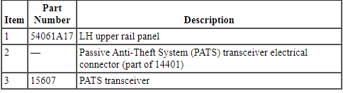
Removal and Installation
- Pulling firmly upward, remove the LH upper rail panel.
- Disconnect the Passive Anti-Theft System (PATS) transceiver electrical connector.
- Using a suitable tool (such as a dentist pick), release the tabs and remove the PATS transceiver.
- NOTE: Replacement of the PATS transceiver does not require
the PATS keys to be programmed into the Instrument Panel Cluster (IPC)
again.
To install, reverse the removal procedure.
 Anti-Theft - Perimeter
DESCRIPTION AND OPERATION
Anti-Theft - Without Intelligent Access (IA)
Overview
The perimeter alarm system deters unauthorized entry to the vehicle by
sounding the horn and flashing all the turn sign ...
 Anti-Theft - Passive Anti-Theft System (PATS), With Intelligent Access (IA)
DESCRIPTION AND OPERATION
Anti-Theft
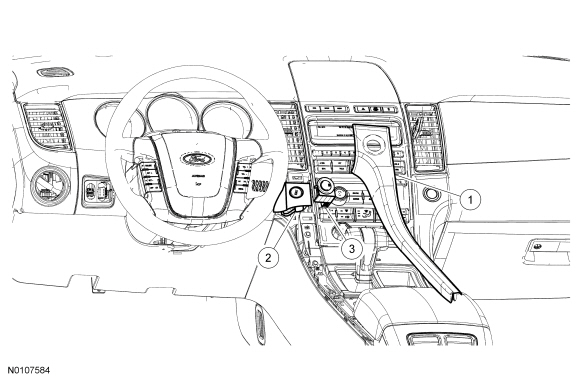
Component Location
RFA Module
Backup Transceiver
TPM Module
Passive Start Antenna (3 required)
Overview
PATS deters the vehicle from theft by ...
Other materials:
Disassembly and Assembly
Wheel and Tire
Special Tool(s)
Disassembly
WARNING: The
tire pressure monitoring system (TPMS) sensor battery may release hazardous
chemicals if exposed to extreme mechanical damage. If these chemicals contact
the skin or eyes, flush immediately with water for a minimum of 15 minutes and
get ...
Fuel Charging and Controls - 3.5L Ti-VCT
SPECIFICATIONS
Material
Torque Specifications
DESCRIPTION AND OPERATION
Fuel Charging and Controls
Component Locations
WARNING: Do
not smoke, carry lighted tobacco or have an open flame of any type when working
on or near any fuel-related component. Highly flammable mixtures are always
present ...
Brakes
GENERAL INFORMATION
Note: Occasional brake noise is normal. If a metal-to-metal, continuous
grinding or continuous squeal sound is present, the brake linings may be
worn out. Have them inspected by an authorized dealer. If your vehicle
has continuous vibration or shudder in the steering wheel wh ...
