DESCRIPTION AND OPERATION
Anti-Theft
Component Location
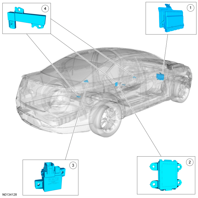
- RFA Module
- Backup Transceiver
- TPM Module
- Passive Start Antenna (3 required)
Overview
PATS deters the vehicle from theft by preventing the ignition from turning on and the engine from starting unless a programmed IA key is detected in the vehicle. PATS does not disable an already running engine.
System Operation
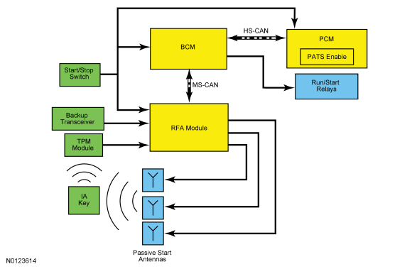
System Diagram
Network Message Chart
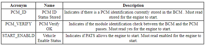
PCM Network Input Messages
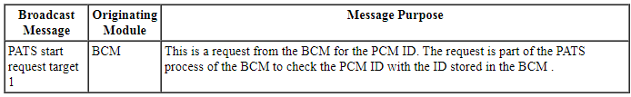
BCM Network Input Messages
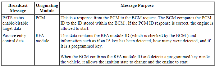
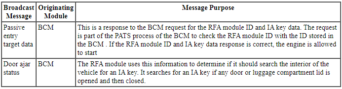
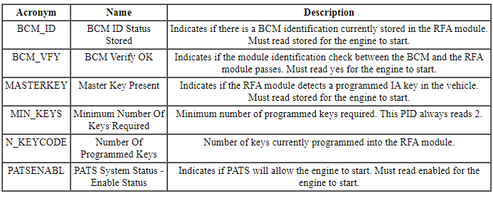
RFA Module Network Input Messages
Passive Anti-Theft System (PATS)
The PATS function is controlled by the BCM and the RFA module.
When the start/stop switch is pressed, the RFA module initiates the key initialization sequence by activating the 3 interior passive start antennas. Each passive start antenna transmits a low frequency signal approximately 1 m (3 ft) radius of each antenna. If an IA key is within range of the 3 interior passive start antennas, the IA key activates.
When the IA key activates, it sends the PATS identification code to the TPM module via a high frequency signal. The TPM module interprets the high frequency signal from the IA key and sends the information to the RFA module over a dedicated network. If the RFA module determines that a programmed IA key is inside the vehicle, it communicates this information to the BCM and the ignition transitions out of OFF.
If the vehicle has a failure of any passive start antenna, the battery in the IA key, or the TPM module, the vehicle can experience a PATS no-start. However, in the event of one of these failures, the IA key can be placed in the backup transceiver slot to allow the vehicle to start. The backup transceiver activates an IA key (if placed in the slot) when the start/stop switch is pressed.
When the ignition transitions out of OFF and the modules initialize, the RFA module, BCM, and the PCM exchange their identifications. If each of the modules receive the correct identification from each other, PATS disables and allows the engine to start. If the PATS prevents the engine from starting, STARTING SYSTEM FAULT displays in the message center and a DTC is stored in one of the 3 modules.
The PATS and the RKE system share the operation of several components including the IA key and the TPM module. If there is a concern with either of these components, the PATS and the RKE system are both affected. REFER to Section 501-14B for information on the RKE and IA features.
NOTE: The IA feature is a programmable parameter and can be enabled/disabled with a scan tool. If the feature is disabled, the IA feature to enter the vehicle and passive starting are inoperative. To start the vehicle, the IA key must be placed in the backup transceiver slot.
The RFA module and the BCM control the ignition modes and, in conjunction with the PCM, control the starting system.
PATS PIDs
In conjunction with DTCs, the PATS PIDs are a useful tool when diagnosing PATS concerns.
BCM Module PID Chart
RFA Module PID Chart
NOTE: The RFA module PATS PIDs do not actively display their current state. They only display the correct state when the ignition is turned to the ON mode
Backup Starting
NOTE: There are certain areas within the vehicle where the IA key may not be detected and the message center displays NO KEY DETECTED. If the IA key is in the far outside edges of the interior (such as in a door map pocket or above a sun visor), it may not be detected. Move the IA key to a different location and try to start the vehicle again.
The vehicle can experience a PATS no start if there is a failure of any passive start antenna, the battery in the IA key, or the TPM module. If this occurs, the NO KEY DETECTED message displays in the message center when the start/stop switch is pressed.
However, in the event of one of these failures, the IA key can be placed in the backup transceiver slot to allow the vehicle to start. The IA key should be placed in the backup transceiver slot with the buttons facing outwards and the key ring up. If a programmed IA key is in the backup transceiver slot when the backup transceiver activates, the IA key and the identification code is sent to the RFA module. The backup slot is located in floor console storage compartment.
No Key Detected Message
NOTE: Some brands/types of mobile phone or laptop computer chargers may cause interference that could lead to a PATS no-start if the IA key is within close proximity of the charger. If a concern is observed, move the IA key away from the charger and attempt to start the vehicle.
There are 2 scenarios in which the No Key Detected message displays in the message center.
The first is when the ignition is off, the START/STOP button is pressed and a programmed Intelligent Access (IA) key is not detected inside the vehicle. If a component failure (such as a dead Intelligent Access (IA) key battery) is causing the No Key Detected message to display, the backup starting method can be used.
The second scenario is when the vehicle is running, the driver exits the vehicle with the programmed Intelligent Access (IA) key and closes the door.
The RFA module activates all 3 passive start antennas to search the inside of the vehicle for an Intelligent Access (IA) key any time a door or the luggage compartment lid is opened and then closed with the vehicle running. The Key outside car message displays in the message center and the horn chirps twice when the ignition is on and an Intelligent Access (IA) key is no longer detected inside the vehicle.
This strategy deters the Intelligent Access (IA) key from being separated from an already running vehicle. If the Intelligent Access (IA) key is no longer in the vehicle, the ignition remains on and the vehicle continues to operate. When the START/STOP button is pressed to turn the ignition off, the ignition can be restarted without an Intelligent Access (IA) key present inside the vehicle for approximately 10 seconds. After 10 seconds have elapsed, a programmed Intelligent Access (IA) key must be present to transition the ignition out of off. If the driver door is opened during the 10-second countdown, a programmed Intelligent Access (IA) key is needed to transition the ignition out of off.
Automatic Engine Idle Shutdown
NOTE: To disable/enable the Automatic Engine Idle Shutdown feature, go into Message Center>Settings>Vehicle.
The automatic engine idle shutdown feature monitors the state of the vehicle to determine when the engine is powered with no user interaction for an extended period of time. When this condition is detected, a message displays in the message center to inform the operator a vehicle shutdown is imminent. This includes shutting down the engine and turning the ignition off. When the shutdown occurs, press the brake and START/STOP button to restart the vehicle.
The conditions required to begin the automatic engine idle shutdown feature are:
- engine running
- brake pedal not pressed
- accelerator pedal not pressed
- remote start not active
- transmission in P (park) or N (neutral)
- diagnostic scan tool not connected to the vehicle
Once these conditions are met, a time-out starts. When the time-out period ends and none of the listed conditions changed, the automatic engine idle shutdown event occurs.
Component Description
Intelligent Access (IA) Key
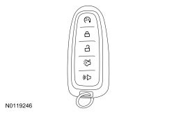
The IA key incorporates both the PATS and the RKE transmitter functions in a single device. The IA key must be located inside the vehicle for engine starting and on the outside for IA features. During key programming procedures, the PATS and RKE transmitter of an IA key are both programmed into the RFA module. The RFA module accepts programming of up to 4 IA keys.
The IA key receives the low frequency signals from the passive start antennas. When the IA key is activated by one of the low frequency signals, it sends out a high frequency signal that is received by the TPM module. The IA key also contains a key blade that is used to unlock the driver door in the event of an electrical failure (such as a drained battery).
Backup Transceiver
The backup transceiver is used as a backup device. If the vehicle fails to start conventionally, an IA key can be placed in the backup slot to allow the vehicle to start. The backup transceiver is located next to the slot and activates any IA key that is placed in the slot. The transceiver is wired to the RFA module. When activated, it sends out a signal to activate an IA key. When the key activates, it sends a signal back to the transceiver which is then sent to the RFA module.
Passive Start Antennas
There are 3 passive start antennas. The passive start antennas are wired to the RFA module. When activated by the RFA module, they transmit a low frequency signal that activates an IA key.
NOTE: Some brands/types of mobile phone or laptop computer chargers may cause interference that could lead to a PATS no-start if the IA key is within a few inches of the charger and the NO KEY DETECTED message displays in the message center. If a concern is observed, move the IA key away from the charger and attempt to start the vehicle.
Interior Passive Start Antenna Ranges
The passive start antennas are used solely for the purpose of starting the vehicle or changing the ignition states. When activated, each antenna sends out a low frequency signal with an approximate range of 1 m (3 ft). A programmed IA key must be in range of 1 of the 3 antennas for PATS to operate.
If an IA key is placed in the far outside edges of the interior, such as above a sun visor or in a door map pocket, the vehicle might experience a no-start condition. If the IA key is located in one of these areas and there is a no-start condition, move the IA key out of the area and attempt to start the vehicle. If the key is outside the range of a passive start antenna when the start/stop switch is pressed, NO KEY DETECTED displays in the message center.
DIAGNOSIS AND TESTING
Anti-Theft
DTC Chart(s)
Diagnostics in this manual assume a certain skill level and knowledge of Ford-specific diagnostic practices. REFER to Diagnostic Methods in Section 100-00 for information about these practices.
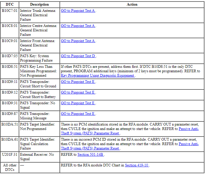
RFA Module DTC Chart
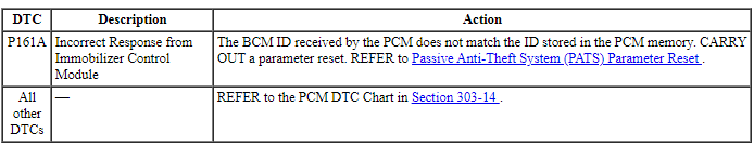
PCM DTC Chart
Symptom Chart(s)
Diagnostics in this manual assume a certain skill level and knowledge of Ford-specific diagnostic practices. REFER to Diagnostic Methods in Section 100-00 for information about these practices.
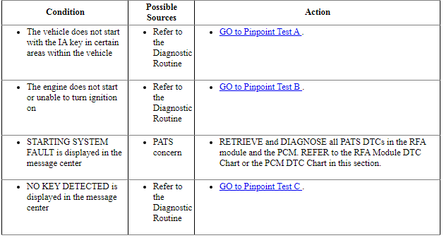
Symptom Chart: Passive Anti-Theft System (PATS)
Pinpoint Tests
Pinpoint Test A: The Vehicle Does Not Start With the IA Key in Certain Areas of the Vehicle
Diagnostic Overview
Diagnostics in this manual assume a certain skill level and knowledge of Ford-specific diagnostic practices. REFER to Diagnostic Methods in Section 100-00 for information about these practices.
Refer to Wiring Diagrams Cell 112, Passive Anti-Theft System for schematic and connector information.
NOTE: Some brands/types of mobile phone or laptop computer chargers may cause interference that could lead to a PATS no-start if the IA key is within a few inches of the charger. If a concern is observed, move the IA key away from the charger and attempt to start the vehicle.
Normal Operation and Fault Conditions
REFER to System Operation - Passive Anti-Theft System (PATS) in Anti-Theft.
REFER to Component Description - Passive Start Antennas in Anti-Theft.
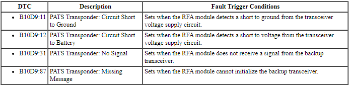
RFA Module DTC Fault Trigger Conditions
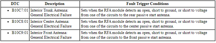
-
Possible Sources
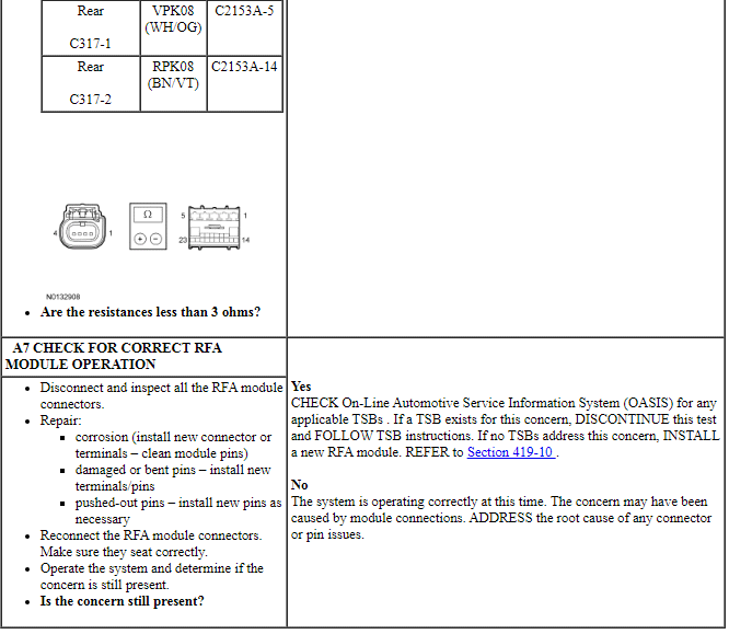
- Wiring, terminals or connectors
- Passive start antenna
- RFA module
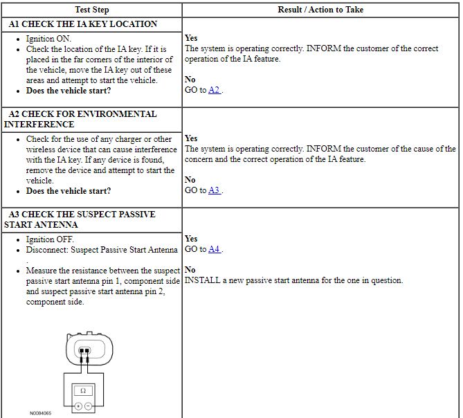
PINPOINT TEST A: THE VEHICLE DOES NOT START WITH THE IA KEY IN CERTAIN AREAS OF THE VEHICLE
Pinpoint Test B: The Engine Does Not Start or Unable To Turn Ignition On
Diagnostic Overview
Diagnostics in this manual assume a certain skill level and knowledge of Ford-specific diagnostic practices. REFER to Diagnostic Methods in Section 100-00 for information about these practices.
Refer to Wiring Diagrams Cell 112, Passive Anti-Theft System for schematic and connector information.
Normal Operation and Fault Conditions
REFER to System Operation - Passive Anti-Theft System (PATS) in Anti-Theft.
REFER to System Operation - Backup Starting in Anti-Theft.
REFER to Component Description - Passive Start Antennas in Anti-Theft.
-
Possible Sources
- Starting system concern
- Driveability concern
- PATS concern
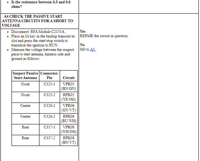
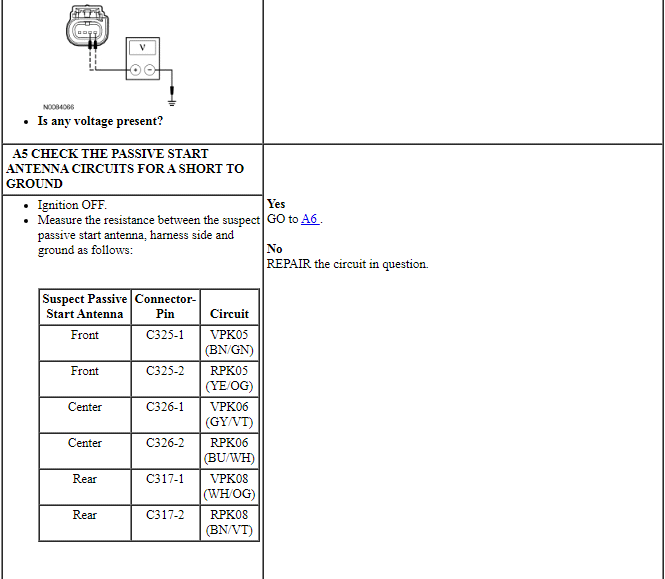
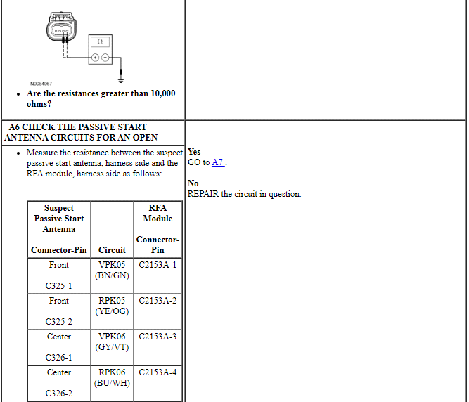
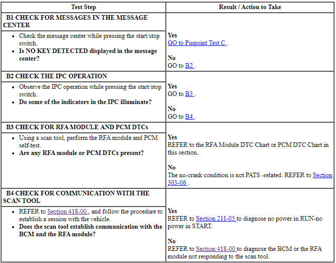
PINPOINT TEST B: THE ENGINE DOES NOT START OR UNABLE TO TURN IGNITION ON
NOTE: The IA feature is a programmable parameter and can be enabled/disabled with a scan tool. If the feature is disabled, the IA feature to enter the vehicle and passive starting are inoperative. To start the vehicle, the IA key has to be placed in the backup transceiver slot.
Pinpoint Test C: NO KEY DETECTED Message Is Displayed In The Message Center
Diagnostic Overview
Diagnostics in this manual assume a certain skill level and knowledge of Ford-specific diagnostic practices. REFER to Diagnostic Methods in Section 100-00 for information about these practices.
Normal Operation and Fault Conditions
REFER to System Operation - NO KEY DETECTED Message in Anti-Theft.
-
Possible Sources
- Environmental interference
- IA key
- IA key battery
- IA key not programmed
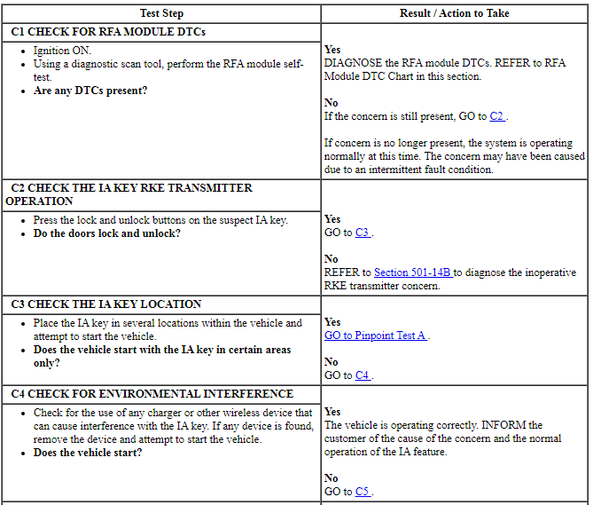
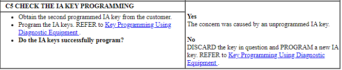
PINPOINT TEST C: NO KEY DETECTED MESSAGE IS DISPLAYED IN THE MESSAGE CENTER
NOTE: This pinpoint test may require a second IA key. If only one key is available, a second IA key must be obtained.
Pinpoint Test D: B10D7:05
Diagnostic Overview
Diagnostics in this manual assume a certain skill level and knowledge of Ford-specific diagnostic practices. REFER to Diagnostic Methods in Section 100-00 for information about these practices.
Refer to Wiring Diagrams Cell 112, Passive Anti-Theft System for schematic and connector information.
Normal Operation and Fault Conditions
When the RFA module enters a key programming state, it activates the backup transceiver to read the key in the backup transceiver slot. When a valid IA key is used and there are no concerns with the PATS, the key is programmed into the RFA module memory.
RFA Module DTC Fault Trigger Conditions

-
Possible Sources
- IA key
- IA key not programmed
Visual Inspection and Diagnostic Pre-checks
- Inspect the IA key for physical damage.
PINPOINT TEST D: B10D7:05
NOTE: This pinpoint test may require a second IA key. If only one key is available, a second IA key must be obtained.

Pinpoint Test E: B10D9:11, B10D9:12, B10D9:31 Or B10D9:87
Diagnostic Overview
Diagnostics in this manual assume a certain skill level and knowledge of Ford-specific diagnostic practices. REFER to Diagnostic Methods in Section 100-00 for information about these practices.
Refer to Wiring Diagrams Cell 112, Passive Anti-Theft System for schematic and connector information.
Normal Operation and Fault Conditions
The RFA module uses the backup transceiver to operate the PATS in the event of a failure of any passive start antenna, a discharged battery in the IA key, or a communication concern with the TPM module. The backup transceiver is also used for IA key programming.
The backup transceiver receives voltage and ground directly from the RFA module. The RFA module controls the backup transceiver through the dedicated clock and data circuits.
RFA Module DTC Fault Trigger Conditions
-
Possible Sources
- Wiring, terminals or connectors
- Backup transceiver
- RFA module
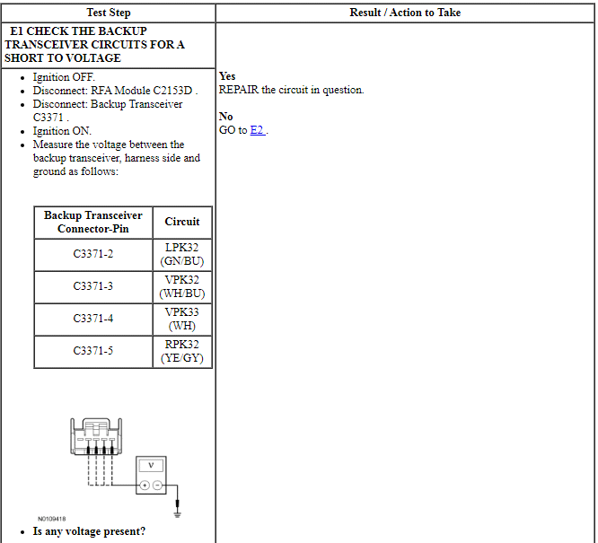
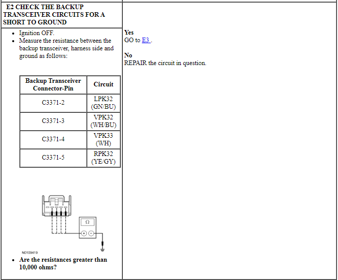
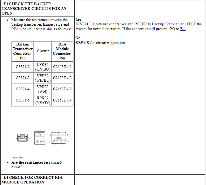
PINPOINT TEST E: B10D9:11, B10D9:12, B10D9:31 OR B10D9:87
GENERAL PROCEDURES
Key Programming - Erase All Key Codes and Program Two Keys
NOTE: This procedure erases all programmed ignition keys from the vehicle memory. The vehicle cannot start until a minimum of 2 keys are programmed into the BCM.
NOTE: This procedure erases all MyKey features on all of the keys that are programmed to the vehicle. All of the keys then operate as normal (admin) keys with no restrictions.
NOTE: To enter PATS security access if no programmed IA keys are available, start a vehicle session using a tear tag or PCM part number. PATS security access can still be granted even with the ignition off.
- From the scan tool, enter TOOLBOX. Select BODY>SECURITY>PATS Functions and follow the IDS on-screen instructions to PATS security access.
- From the scan tool menu, select "Ignition Key Code Erase" and follow the IDS on-screen instructions until the key erase procedure completes.
- All keys are now erased. Leave the scan tool connected and program 2 keys. REFER to Key Programming Using Diagnostic Equipment.
Key Programming Using Diagnostic Equipment
NOTE: To enter PATS security access if no programmed IA keys are available, start a vehicle session using a tear tag or PCM part number. PATS security access can still be granted even with the ignition off.
- Insert the unprogrammed IA key into the backup transceiver slot.
- From the scan tool, enter TOOLBOX. Select Body>Security>PATS Functions and follow the IDS on-screen instructions to enter PATS security access.
- From the scan tool menu select "Program additional ignition key" and follow the IDS on-screen instructions.
- NOTE: The engine does not start until there are at least 2 keys
programmed.
The engine should now start with the new IA key.
- If it is desired to program additional IA key, insert the additional IA key
into the backup transceiver slot and repeat Step 3 for the additional key
that needs to be programmed.
- A total of 4 IA keys can be programmed
Key Programming Using Two Programmed Keys
NOTE: This procedure works only if 2 programmed keys are available. If 2 programmed keys are not available, refer to Key Programming Using Diagnostic Equipment.
NOTE: This procedure works only if the customer spare key programming is enabled. If the customer spare key programming is disabled, REFER to Key Programming - Enable/Disable Spare Key Programming or Key Programming Using Diagnostic Equipment.
NOTE: Steps 1-7 must be carried out within 30 seconds to successfully enter programming mode.
- Begin with the ignition OFF.
- Place 2 programmed IA keys inside the passenger compartment.
- Insert an unprogrammed IA key in the backup transceiver slot.
- Press unlock on the door lock control switch 3 times.
- Press and release the brake pedal once.
- Press lock on the door lock control switch 3 times.
- NOTE: After this step, the indicator on the start/stop switch
begins to flash rapidly, indicating that programming mode has been entered.
Press and release the brake pedal once.
- Press the start/stop switch to program the new IA key. A message displays on the message center indicating the new IA key has been programmed.
- Exiting the programming mode is accomplished when any of the following
occur:
- The lock or unlock on the door lock control switch is pressed
- One minute has passed since entering programming mode or since an IA key was programmed.
- The brake pedal is applied.
- The ignition transitions out of OFF.
- The maximum number of keys are programmed.
- Verify the operation of the new IA key by pressing the lock and unlock buttons on the IA key, then place the new key inside the passenger compartment and start the engine with the new IA key. Make sure the original keys are outside of the vehicle when verifying the new IA key operation.
- If it is desired to program an additional IA key, repeat Steps 1-8.
- A total of 4 IA keys can be programmed
Key Programming - Enable/Disable Spare Key Programming
NOTE: This procedure provides the capability to enable/disable the normal customer spare key programming procedure detailed in the Owner's Literature and the Key Programming Using Two Programmed Keys procedure. If spare key programming is disabled, spare keys can only be programmed by using the scan tool. REFER to Key Programming Using Diagnostic Equipment.
- Place the ignition in RUN.
- From the scan tool, enter TOOLBOX. Select Body>Security>PATS Functions and follow the IDS on-screen instructions to enter PATS security access.
- From the scan tool menu select "Customer Spare Key Programming Enable" or "Customer Spare Key Programming Disable" and follow the IDS on-screen instructions.
Passive Anti-Theft System (PATS) Parameter Reset
NOTE: To enter PATS security access if the RFA module or BCM is replaced, or if no programmed IA keys are available, start a vehicle session using a tear tag or PCM part number. PATS security access can still be granted even with the ignition off.
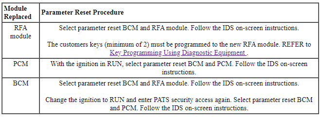
NOTE: There are 2 parameter reset procedures in the scan tool. Select the appropriate procedure depending upon which module was replaced.
- From the scan tool, enter TOOLBOX. Select Body>Security>PATS Functions and follow the IDS on-screen instructions to enter PATS security access.
- Select the appropriate parameter reset from the table.
REMOVAL AND INSTALLATION
Backup Transceiver
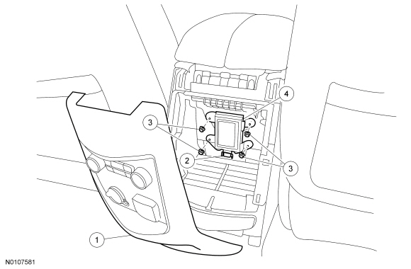
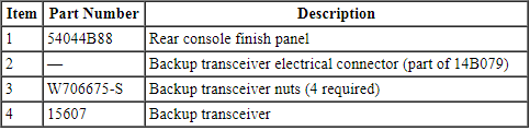
Removal and Installation
- Pulling firmly in a rearward direction, remove the rear console finish panel and position it aside.
- Disconnect the backup transceiver electrical connector.
- Remove the 4 nuts and the backup transceiver.
- NOTE: Replacement of the backup transceiver does not require the
Intelligent Access (IA) keys to be programmed into the Remote Function
Actuator (RFA) module again.
To install, reverse the removal procedure.
Passive Start Antenna - Front
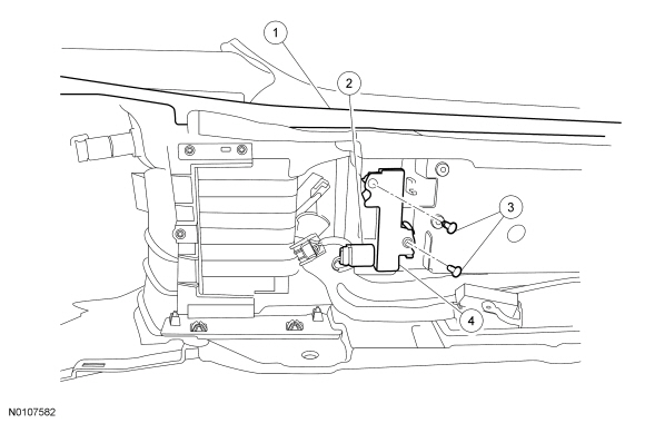
Removal and Installation
- Remove the floor console. For additional information, refer to Section 501-12.
- Pull the red lock tab outward and disconnect the front floor console passive start antenna electrical connector.
- Remove the 2 screws and the front floor console passive start antenna.
- To install, reverse the removal procedure.
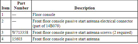
Passive Start Antenna - Center
Removal and Installation
- Remove the floor console. For additional information, refer to Section 501-12.
- Pull the red lock tab outward and disconnect the rear floor console passive start antenna electrical connector.
- Remove the 2 screws and the rear floor console passive start antenna.
- To install, reverse the removal procedure.
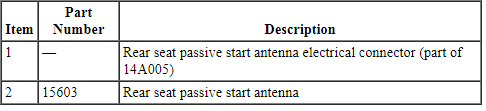
Passive Start Antenna - Rear
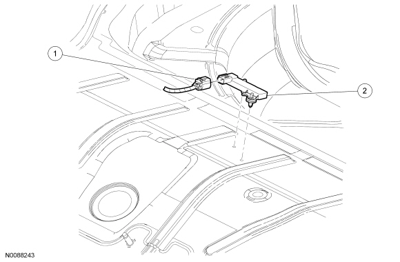
Removal and Installation
- Remove the rear seat cushion. For additional information, refer to Section 501-10.
- Pull the carpet forward to uncover the rear seat passive start antenna.
- Disconnect the rear seat passive start antenna electrical connector.
- Using a suitable tool (such as a trim removal tool), pry the 2 pushpins upward to release them from the floorpan and remove the rear seat passive start antenna.
- To install, reverse the removal procedure.
 Anti-Theft - Passive Anti-Theft System (PATS), Without Intelligent Access (IA)
DESCRIPTION AND OPERATION
Anti-Theft
Overview
PATS deters the vehicle from theft by preventing the engine from starting
unless a programmed PATS key is in the ignition. PATS ...
 Remote Convenience
DESCRIPTION AND OPERATION
Universal Transmitter
Overview
The universal transmitter operates garage doors, gates and home or office
lighting and security systems.
System Operation
Universal Home Trans ...
Other materials:
Pedals
Adjustable pedals
WARNING: Never adjust the accelerator and brake pedal with
feet on the pedals while the vehicle is moving.
The control is located on the left side of the steering column. Press and
hold the appropriate control to move the pedals.
A. Farther
B. Closer
The pedal positions ar ...
Using voice recognition
This system helps you control many features using voice commands.
This allows you to keep your hands on the wheel and focus on what is in
front of you. The system provides feedback through audible tones,
prompts, questions and spoken confirmations depending on the situation
and the chosen leve ...
Diagnosis and Testing
Automatic Transmission
Special Tool(s)
Material
DTC Chart
Diagnostics in this manual assume a certain skill level and knowledge of
Ford-specific diagnostic practices. Refer to Diagnostic Methods in Section
100-00 for information about these practices.
When the electrical connector ...
