Engine Cooling
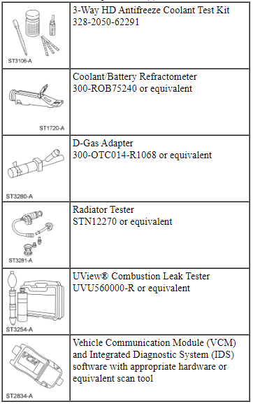
Special Tool(s)
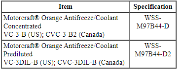
Material
Principles of Operation
Engine coolant flows primarily from the engine to the radiator circuit and back to the coolant pump. Coolant is sent from the coolant pump through the engine block and cylinder heads. Separate circuits from the engine also feed the heater core and turbochargers (if equipped) with coolant. The coolant pump circulates the coolant. For 3.5L Ti-VCT, 3.7L Ti-VCT and 3.5L GTDI engines, the coolant pump is operated by engine rotation through the timing chain sprocket. For 2.0L GTDI engines, the coolant pump is operated by engine rotation through the accessory drive belt pulley. The coolant thermostat is a control valve actuated by coolant temperature. When the thermostat is closed, coolant flow bypasses the radiator circuit and returns to the coolant pump. When the thermostat is opened, coolant flows through the radiator circuit to transfer engine-generated heat to the outside air.
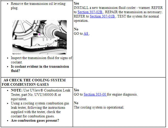
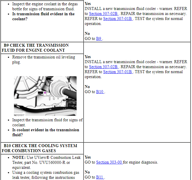
For 2.0L GTDI engines, the transmission fluid cooler - warmer is mounted on top of the transmission. On initial startup, the temperature control valve bypasses the transmission fluid cooler - warmer circuit, and the coolant flows back to the engine. If the coolant is not extremely cold (above -9ÂşC [15ÂşF] ), the temperature control valve directs coolant to the transmission fluid cooler - warmer circuit when the transmission is shifted to any gear other than park or neutral.
The degas bottle removes air from the cooling system, allows for coolant expansion and system pressurization, replenishes coolant to the cooling system and serves as the location for service fill.
The cooling fan draws air through the radiator to help cool the system coolant as it passes through the radiator.
The thermostat monitor is a function of the PCM and is designed to verify correct thermostat operation. The monitor executes once per drive cycle and has a monitor run duration of 300-800 seconds. If a malfunction occurs, DTC P0125 or P0128 is set, and the Malfunction Indicator Lamp (MIL) illuminates.
For the coolant flow diagrams, refer to Engine Cooling in the Description and Operation portion of this section.
Inspection and Verification
WARNING: Always allow the engine to cool before opening the cooling system. Do not unscrew the coolant pressure relief cap when the engine is operating or the cooling system is hot. The cooling system is under pressure; steam and hot liquid can come out forcefully when the cap is loosened slightly. Failure to follow these instructions may result in serious personal injury.
NOTICE: The engine cooling system is filled with Motorcraft Orange Antifreeze/Coolant. Always fill the cooling system with the manufacturer's specified coolant. Chemically flush the cooling system if a non-specified coolant has been used. Refer to Cooling System Flushing. Failure to follow these instructions may damage the engine or cooling system.
NOTICE: Use Motorcraft Orange Antifreeze/Coolant. Do not mix coolant types. Mixing coolant types degrades the coolant corrosion protection and may damage the engine or cooling system.
NOTICE: Do not use stop-leak style pellets/products as an additive in this engine cooling system. The addition of stop-leak style pellets/products can clog or damage the cooling system, resulting in degraded cooling system performance and/or failure.
NOTE: During normal vehicle operation, Motorcraft Orange Antifreeze/Coolant may change color from orange to pink or light red. As long as the engine coolant is clear and uncontaminated, this color change does not indicate the engine coolant has degraded nor does it require the engine coolant to be drained, the system to be flushed, or the engine coolant to be replaced.
NOTE: Vehicles have a pressure relief cap on the degas bottle and no radiator cap.
- Verify the customer concern.
- Visually check the engine coolant level at the degas bottle when the system is cold.
- Make sure the pressure relief cap is installed correctly.
- Record any cooling system DTCs retrieved. Refer to the PCM DTC Chart in this section for DTC descriptions.
- NOTE: Take note of any coolant odor or steam coming from cooling
system components.
If the system coolant is filled correctly and no DTCs associated with fail-safe cooling are retrieved, verify the customer's concern by operating the engine to duplicate the condition.
- NOTE: For the coolant flow diagrams, refer to Engine
Cooling.
Visually inspect for obvious signs of any mechanical or electrical damage.
Visual Inspection Chart
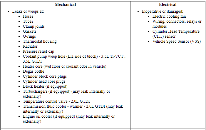
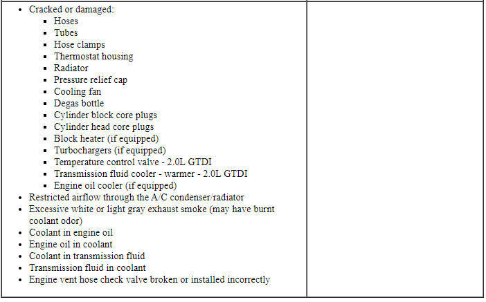
- If the inspection reveals an obvious concern that can be readily identified, repair it as necessary. Test the system for normal operation.
- NOTICE: The engine cooling system is filled with Motorcraft
Orange Antifreeze/Coolant. Always fill the cooling system with the
manufacturer's specified coolant. Chemically flush the cooling system if a
non-specified coolant has been used. Refer to Cooling System Flushing.
Failure to follow these instructions may damage the engine or cooling
system.
NOTICE: Use Motorcraft Orange Antifreeze/Coolant. Do not mix coolant types. Mixing coolant types degrades the coolant corrosion protection and may damage the engine or cooling system.
NOTICE: Do not use stop-leak style pellets/products as an additive in this engine cooling system. The addition of stop-leak style pellets/products can clog or damage the cooling system, resulting in degraded cooling system performance and/or failure.
NOTE: During normal vehicle operation, Motorcraft Orange Antifreeze/Coolant may change color from orange to pink or light red. As long as the engine coolant is clear and uncontaminated, this color change does not indicate the engine coolant has degraded nor does it require the engine coolant to be drained, the system to be flushed, or the engine coolant to be replaced.
Inspect the coolant condition.- Inspect the coolant color.
- If Motorcraft Orange Antifreeze/Coolant has a clear or pale color, this indicates higher water content than required. Test the engine coolant freezing point range with the Coolant/Battery Refractometer. The freezing point should be in the range -34ÂşC (-30ÂşF) to -37ÂşC (-34ÂşF). If the vehicle is driven in cold climates less than -37ÂşC (-34ÂşF), it may be necessary to increase the coolant concentration to get adequate freeze protection. Recommended coolant concentration is 48/52 to 50/50 (freeze protection -34ÂşC (-30ÂşF) to -37ÂşC (-34ÂşF) engine coolant to distilled water.
- Discoloration of Motorcraft Orange Antifreeze/Coolant may indicate that incorrect coolant may have been added to the system. Use of incorrect (green or yellow) coolant degrades the corrosion protection of Motorcraft Orange Antifreeze/Coolant. Addition of Motorcraft Specialty Green Engine Coolant may cause the color to appear a murky green-brown color. The addition of Motorcraft Premium Gold Engine Coolant, however, may not change the color or appearance of the orange colored coolant. Detection of contamination with Motorcraft Premium Gold Engine Coolant is determined by the presence of nitrite. If contamination with Motorcraft Premium Gold Engine Coolant is suspected, test the coolant with the 3-Way HD Antifreeze Coolant Test Kit. Follow the nitrite testing directions in the kit to determine if nitrite is present in the system. If nitrite is present, flush the system and refill with the correct mixture of Motorcraft Orange Antifreeze/Coolant and distilled water. Refer to Cooling System Flushing.
- A darker color with the presence of debris could indicate a commercially available stop-leak may have been used and could result in loss of coolant flow to critical parts of the engine. If sediment is present in the coolant sample, flush the system and refill with the correct mixture of Motorcraft Orange Antifreeze/Coolant and distilled water. Refer to Cooling System Flushing in this section.
- A light or reddish brown color or reddish brown particles indicate that rust may be present in the cooling system. Flush the system and refill with the correct mixture of Motorcraft Orange Antifreeze/Coolant and distilled water. Refer to Cooling System Flushing.
- An iridescent sheen on top of the coolant could indicate a trace of oil is entering the system. For information on engine diagnosis, refer to Section 303-00. Flush the cooling system. Refer to Cooling System Flushing.
- A milky brown color may indicate that engine oil is entering the cooling system. Pressure test the cooling system. Refer to Component Tests in this section. If engine oil is suspected, the cause of the leak may be internal to the engine. Refer to Section 303-00. Flush the cooling system. Refer to Cooling System Flushing.
- If the engine coolant appearance is acceptable, test the engine
coolant freezing point range with the Coolant/Battery Refractometer. The
freezing point should be in the range -34ÂşC (-30ÂşF) to -37ÂşC (-34ÂşF). If
the vehicle is driven in cold climates less than -37ÂşC (-34ÂşF), it may
be necessary to increase the coolant concentration to get adequate
freeze protection. Recommended coolant concentration is 48/52 to 50/50
(freeze protection -34ÂşC (-30ÂşF) to -37ÂşC (-34ÂşF) engine coolant to
distilled water.
- Maximum coolant concentration is 60/40 for cold weather areas.
- Minimum coolant concentration is 40/60 for warm weather areas.
- Adjust coolant range and level if necessary:
- If coolant is low, add Motorcraft Orange Antifreeze/Coolant Prediluted.
- If the engine coolant tests too weak, remove some of the engine coolant and add Motorcraft Orange Antifreeze/Coolant Concentrated until the readings are within acceptable levels.
- If the engine coolant tests strong, remove some of the engine coolant and add distilled water until the readings are within acceptable levels.
- Inspect the coolant color.
- If an obvious cause for an observed or reported concern is found, correct the cause and test the system for normal operation before proceeding to the next step.
- NOTE: Make sure to use the latest scan tool software release.
If the cause is not visually evident, connect the scan tool to the DLC.
- NOTE: The VCM LED prove out confirms power and ground from
the DLC are provided to the VCM.
If the scan tool does not communicate with the VCM :
- check the VCM connection to the vehicle.
- check the scan tool connection to the VCM.
- refer to Section 418-00, No Power To The Scan Tool, to diagnose no power to the scan tool.
- If the scan tool does not communicate with the vehicle:
- verify the ignition key is in the ON position.
- verify the scan tool operation with a known good vehicle.
- refer to Section 418-00, The PCM Does Not Respond To The Scan Tool, to diagnose no response from the PCM.
- Carry out the network test.
- If the scan tool responds with no communication for one or more modules, refer to Section 418-00.
- If the network test passes, retrieve and record CMDTCs.
- Clear the continuous DTCs and carry out the self-test diagnostics PCM.
- If the DTCs recovered are related to the concern, go to the PCM DTC Chart. For all other PCM DTCs, refer to Section 303-14.
- If no DTCs related to the concern are retrieved, GO to Symptom Chart.
DTC Chart
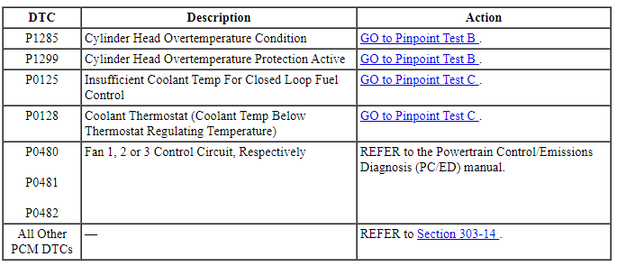
PCM DTC Chart
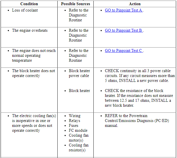
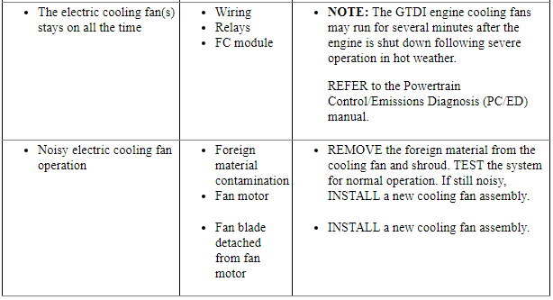
Symptom Chart
Pinpoint Tests
Pinpoint Test A: Loss of Coolant
Normal Operation
The engine cooling system is a closed system providing for coolant expansion and contraction and also changes in pressure as coolant warms and cools with engine operation. Various gaskets, seals, hoses and clamps contain coolant within the cooling system and keep other fluids and contaminants from entering the cooling system.
Coolant loss can be attributed to either external or internal leaks anywhere within the cooling system.
For the coolant flow diagrams, refer to Engine Cooling.
-
This pinpoint test is intended to diagnose the following:
- Coolant hoses or tubes
- Hose clamps
- Thermostat O-ring seal or gasket
- Coolant pump O-ring seal or gasket
- Thermostat housing
- Radiator
- Pressure relief cap
- Coolant pump leaking from weep hole (LH side of block - 3.5L Ti-VCT, 3.7L Ti-VCT or 3.5L GTDI )
- Heater core
- Engine gaskets (may leak internally or externally)
- Degas bottle
- Cylinder block core plugs
- Cylinder head core plugs
- Block heater (if equipped)
- Turbochargers (if equipped)
- Oil cooler (if equipped)
- Temperature control valve - 2.0L GTDI
- Transmission fluid cooler - warmer - 2.0L GTDI
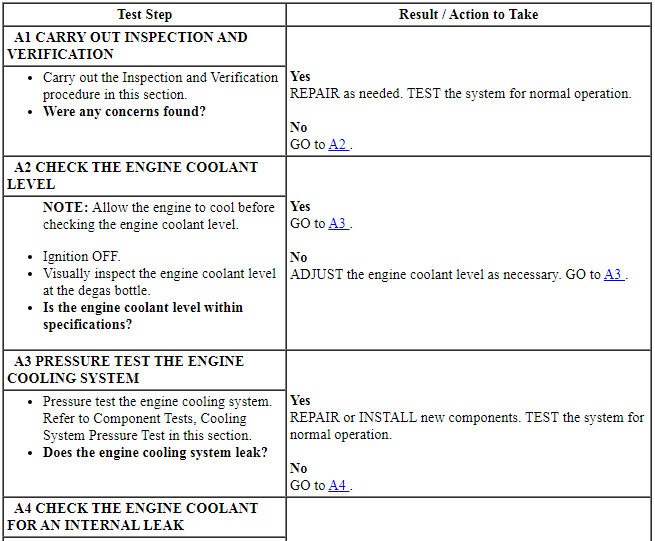
PINPOINT TEST A: LOSS OF COOLANT
WARNING: Always allow the engine to cool before opening the cooling system. Do not unscrew the coolant pressure relief cap when the engine is operating or the cooling system is hot. The cooling system is under pressure; steam and hot liquid can come out forcefully when the cap is loosened slightly. Failure to follow these instructions may result in serious personal injury.
Pinpoint Test B: The Engine Overheats
Normal Operation
The engine cooling system maintains engine temperature during operation. Correct coolant flow through the engine, radiator and remainder of cooling system passages and components is essential to maintaining a correct engine temperature.
Engine coolant flows primarily from the engine to the radiator circuit and back to the coolant pump. Coolant is sent from the coolant pump through the engine block and cylinder heads. Separate circuits from the engine also feed the heater core and turbochargers (if equipped) with coolant. The coolant pump circulates the coolant. For 3.5L Ti-VCT, 3.7L Ti-VCT and 3.5L GTDI engines, the coolant pump is operated by engine rotation through the timing chain sprocket. For 2.0L GTDI engines, the coolant pump is operated by engine rotation through the accessory drive belt pulley. The coolant thermostat is a control valve actuated by coolant temperature. When the thermostat is closed, coolant flow bypasses the radiator circuit and returns to the coolant pump. When the thermostat is opened, coolant is allowed to flow through the radiator circuit in order to transfer engine-generated heat to the outside air.
Engine overheating generally occurs when there is a disruption in the ability to control either coolant flow at the correct rate, the inability to transfer heat from the engine through the coolant (including low coolant) or an inability to transfer engine-generated heat to the outside air through the radiator.
For the coolant flow diagrams, refer to Engine Cooling.
- DTC P1285 (Cylinder Head Overtemperature Condition) - Indicates an engine overheat condition was sensed by the Cylinder Head Temperature (CHT) sensor.
- DTC P1299 (Cylinder Head Overtemperature Protection Active) - Indicates an engine overheat condition was detected by the CHT sensor. A failure mode effects management strategy called fail-safe cooling was activated to cool the engine.
-
This pinpoint test is intended to diagnose the following:
- Radiator
- Thermostat
- Low coolant level
- External engine coolant leak
- Airlock in system
- Pressure relief cap installation
- Restricted airflow through the A/C condenser/radiator
- Internal engine coolant leak
- Coolant condition/concentration
- Non-OEM engine enhancement components
- Electric cooling fan
- Engine temperature gauge
- CHT sensor
- Heater core
- Coolant pump
- Coolant flow restriction
- Missing or broken engine vent hose check valve or incorrect orientation of check valve
- Temperature control valve - 2.0L GTDI
- Transmission fluid cooler - warmer - 2.0L GTDI
PINPOINT TEST B: THE ENGINE OVERHEATS
WARNING: Always allow the engine to cool before opening the cooling system. Do not unscrew the coolant pressure relief cap when the engine is operating or the cooling system is hot. The cooling system is under pressure; steam and hot liquid can come out forcefully when the cap is loosened slightly. Failure to follow these instructions may result in serious personal injury.
Pinpoint Test C: The Engine Does Not Reach Normal Operating Temperature
Normal Operation
The engine cooling system maintains engine temperatures during operation. Correct coolant flow through the engine, radiator and remainder of cooling system passages and components is essential to maintaining a correct engine temperature.
Engine coolant flows primarily from the engine to the radiator circuit and back to the coolant pump. From the coolant pump, coolant is sent through the engine block and cylinder heads. Separate circuits from the engine also feed the heater core and turbochargers (if equipped) with coolant. The coolant pump circulates the coolant. For 3.5L Ti-VCT, 3.7L Ti-VCT and 3.5L GTDI engines, the coolant pump is operated by engine rotation through the timing chain sprocket. For 2.0L GTDI engines, the coolant pump is operated by engine rotation through a the accessory drive belt pulley. The coolant thermostat is a control valve actuated by coolant temperature. When the thermostat is closed, coolant flow bypasses the radiator circuit and returns to the coolant pump. When the thermostat is opened, coolant flows through the radiator circuit to transfer engine generated heat to the outside air.
Concerns of engine inability to reach normal operating temperature typically occur when the rate of coolant flow through some coolant circuits (radiator, heater core) is more than expected given the conditions, or when the electric cooling fans operate all the time. Heat is not allowed to build in the engine because a heat exchanger is removing too much heat, including the radiator, heater core and oil cooler. In addition, perceived concerns that the engine does not reach normal operating temperature can be related to a low coolant level or trapped air which does not allow for hot coolant to be available at the heater core, an inoperative climate control system, or for concerns perceived or related to an incorrect engine temperature gauge indication.
For the coolant flow diagrams, refer to Engine Cooling.
- DTC P0125 (Insufficient Coolant Temp for Closed Loop Fuel Control) - Indicates the Cylinder Head Temperature (CHT) sensor has not achieved the required temperature level to enter closed loop operating conditions within a specified amount of time after starting the engine.
- DTC P0128 (Coolant Thermostat [Coolant Temp Below Thermostat Regulating Temperature] ) - Indicates that the thermostat monitor has not achieved the required engine operating temperature within a specified amount of time after starting the engine.
-
This pinpoint test is intended to diagnose the following:
- Low coolant level
- Thermostat
- CHT sensor
- Engine Coolant Temperature (ECT) gauge
- Engine cooling fan always on
PINPOINT TEST C: THE ENGINE DOES NOT REACH NORMAL OPERATING TEMPERATURE
WARNING: Always allow the engine to cool before opening the cooling system. Do not unscrew the coolant pressure relief cap when the engine is operating or the cooling system is hot. The cooling system is under pressure; steam and hot liquid can come out forcefully when the cap is loosened slightly. Failure to follow these instructions may result in serious personal injury.
Component Tests
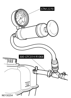
Cooling System Pressure Test
WARNING: Always allow the engine to cool before opening the cooling system. Do not unscrew the coolant pressure relief cap when the engine is operating or the cooling system is hot. The cooling system is under pressure; steam and hot liquid can come out forcefully when the cap is loosened slightly. Failure to follow these instructions may result in serious personal injury.
NOTE: Vehicles have a pressure relief cap on the degas bottle and no radiator cap.
- Turn the engine OFF.
- Check the engine coolant level and adjust as necessary.
- Attach the Pressure Tester to the degas bottle nipple and overflow hose. Install a pressure test pump to the quick connect fitting of the test adapter.
- NOTICE: Do not pressurize the cooling system beyond the
maximum pressure listed in the Specifications table in this section or
cooling system components may be damaged.
NOTE: If the plunger of the pressure tester is pressed too fast, an erroneous pressure reading results.
Slowly press the plunger of the pressure test pump until the pressure gauge reading stops increasing and note the highest pressure reading obtained. If the pressure reading exceeds the maximum cap pressure listed in the Specifications table, install a new pressure relief cap.
- If the system does not hold pressure, remove the pressure relief cap and wash in clean water to dislodge all the foreign material from the gasket. Check the sealing surface in the filler neck of the degas bottle for nicks or cuts. Install the pressure relief cap.
- Pressurize the engine cooling system as described in Step 4 above. Observe the gauge reading for approximately 2 minutes. Pressure should not drop during this time. If the pressure drops within this time, inspect for leaks and repair as necessary.
- If no leaks are found and the pressure drops. the pressure relief cap may be leaking. Install a new pressure relief cap and retest the system.
- If no leaks are found after a new pressure relief cap is installed, and the pressure drops, the leak may be internal to the engine. Inspect the coolant for engine oil and the engine oil for coolant. Refer to Section 303-00 to diagnose the engine.
- Release the system pressure by loosening the pressure relief cap. Check the coolant level and adjust as necessary.
Thermostat
Install a new thermostat only after at least one of the following tests and checks have been carried out:
- Pinpoint Test B or C
- Thermostat Visual Inspection
Thermostat Visual Inspection
- Remove the thermostat.
- Examine the thermostat for signs of damage including:
- Valve not fully seated (light visible through the valve)
- Foreign material lodged in the main valve
- Bent or broken frame or flange
- Bent or broken spring
- Bent or broken valve or valve stem
- Wax leaking from wax reservoir or a bulge in the reservoir
- Any other damage or distortion
- NOTE: If no damage is found during the inspection, do not attempt
to open the thermostat using hot water or other heat sources. This method is
not an accurate means to test the function of the thermostat and may damage
the thermostat.
If damage is found during the inspection, remove any foreign material or broken pieces and install a new thermostat.
Radiator Leak Test, Removed From Vehicle
NOTICE: Never leak test an aluminum radiator in the same water that copper/brass radiators are tested in. Flux and caustic cleaners may be present in the cleaning tank and they will damage aluminum radiators.
NOTE: Clean the radiator before leak testing to avoid contamination of tank.
- Leak test the radiator in clean water with air pressurized to the maximum pressure listed in the Specifications table.
 Specifications, Description and Operation
SPECIFICATIONS
Material
a 50/50 mixture coolant and distilled water.General
Specifications
Torque Specifications
a Refer to the procedure.
b Tighten to 5 Nm (44 lb-in) plus an addi ...
 General Procedures
Cooling System Draining, Filling and Bleeding
Special Tool(s)
Material
Draining
With the vehicle in NEUTRAL, position it on a hoist. Refer to Section
100-02.
WARNING:
Always allo ...
Other materials:
Transporting the vehicle
If you need to have your vehicle towed, contact a professional towing
service or, if you are a member of a roadside assistance program, your
roadside assistance service provider.
We recommend the use of a wheel lift and dollies or flatbed equipment
to tow your vehicle. Do not tow with a slin ...
Dual automatic temperature control
Note: You can switch temperature units between Fahrenheit and Celsius.
See Menu features in the MyFord Touch or MyLincoln Touch chapter.
A. Power/Driver temperature control: Press to turn the climate
control system off and on. When the system is off, outside air cannot
enter the vehicle.
...
Audible warnings and indicators
Key In Ignition Warning Chime
Sounds when the key is left in the ignition in the off or accessory
position and the driver’s door is opened.
Keyless Warning Alert (If Equipped)
Sounds the horn twice when you exit your vehicle with the intelligent
access key, after the last door is closed and y ...
