SPECIFICATIONS
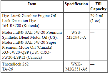
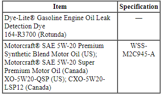
Material
DESCRIPTION AND OPERATION
Engine
NOTICE: When repairing engines, all parts must be contamination free. If contamination/foreign material is present when repairing an engine, premature engine failure may occur.
NOTE: Specifications show the expected minimum or maximum condition. Refer to the appropriate section in Group 303 for the procedure.
NOTE: If a component fails to meet the specifications, it is necessary to refinish it or install a new component. Wear limits are provided as an aid to determine if the component can be refinished. A new component must be installed when any component fails to meet specifications and cannot be refinished.
NOTE: This section contains information, steps and procedures that may not be specific to this engine.
This section covers general procedures and diagnosis and testing of the engine system, except for exhaust emission control devices, which are covered in the Powertrain Control/Emissions Diagnosis (PC/ED) manual.
The engine incorporates the following features: Refer to the appropriate section in Group 303 for the procedure.
- Crankcase ventilation or breather system
- Exhaust emission control system
- Evaporative Emission (EVAP) control system
Some engines incorporate a fail-safe cooling system. Refer to the appropriate section in Group 303 for the procedure.
The engine, fuel system, ignition system, emissions system and exhaust system all affect exhaust emission levels and must be maintained according to the maintenance schedule. Refer to the scheduled Maintenance Guide.
Correct engine identification is required to order parts. Refer to the appropriate section in Group 303 for the procedure.
For complete vehicle and engine identification codes, refer to Section 100-01.
DIAGNOSIS AND TESTING
Engine
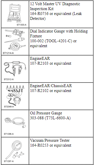
Special Tool(s)
Material
There are 2 diagnostic paths that can be followed depending on the type of engine concern. Carry out Inspection and Verification - Engine Performance or Inspection and Verification - NVH.
Inspection and Verification - Engine Performance
- Verify the customer concern by operating the engine to duplicate the condition.
- Visually inspect for obvious signs of mechanical damage. Refer to the
following chart.
Visual Inspection Chart
Mechanical
- Engine coolant leaks
- Engine oil leaks
- Fuel leaks
- Damaged or severely worn parts
- Loose mounting bolts, studs and nuts
- Compressor housing inlet and outlet circuit and piping (Gasoline Turbocharged Direct Injection (GTDI) only)
- Turbine housing inlet, outlet and piping ( GTDI only)
- Turbocharger actuator tubing or linkage ( GTDI only)
- If the inspection reveals obvious concerns that can be readily identified, repair as necessary.
- NOTE: Make sure to use the latest scan tool software release.
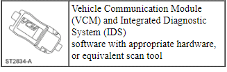
If the cause is not visually evident, connect the scan tool to the Data Link Connector (DLC).
- NOTE: The Vehicle Communication Module (VCM) LED
prove out confirms power and ground from the DLC are provided to the VCM.
If the scan tool does not communicate with the VCM :
- check the VCM connection to the vehicle.
- check the scan tool connection to the VCM.
- refer to Section 418-00, No Power To The Scan Tool, to diagnose no power to the scan tool.
- If the scan tool does not communicate with the vehicle:
- verify the ignition key is in the ON position.
- verify the scan tool operation with a known good vehicle.
- refer to Section 418-00 to diagnose no response from the PCM.
- Carry out the network test.
- If the scan tool responds with no communication for one or more modules, refer to Section 418-00.
- If the network test passes, retrieve and record Continuous Memory Diagnostic Trouble Codes (CMDTCs).
- Clear the continuous DTCs and carry out the self-test diagnostics for the PCM.
- If the DTCs retrieved are related to the concern, go to the DTC Chart, refer to Section 419-10.
- If no DTCs related to the concern are retrieved, GO to Symptom Chart - Engine.
Inspection and Verification - NVH
- NVH symptoms should be identified using the diagnostic tools and techniques that are available. For a list of these techniques, tools, an explanation of their uses and a glossary of common terms, refer to Section 100-04.
- Verify the customer concern by operating the engine to duplicate the condition.
- Check the engine oil level and check the oil for contamination. Low engine oil level or contaminated oil are common causes of engine noise. If the oil is contaminated, the source of the contamination must be identified and repaired as necessary.
- Visually inspect for obvious signs of mechanical damage. Refer to the following chart.
- If the inspection reveals obvious concerns that can be readily identified, repair as necessary.
- NOTE: Make sure to use the latest scan tool software release.
If the cause is not visually evident, connect the scan tool to the DLC.
- NOTE: The VCM LED prove out confirms power and
ground from the DLC are provided to the VCM.
If the scan tool does not communicate with the VCM :
- check the VCM connection to the vehicle.
- check the scan tool connection to the VCM.
- refer to Section 418-00, No Power To The Scan Tool, to diagnose no power to the scan tool.
- If the scan tool does not communicate with the vehicle:
- verify the ignition key is in the ON position.
- verify the scan tool operation with a known good vehicle.
- refer to Section 418-00 to diagnose no response from the PCM.
- Carry out the network test.
- If the scan tool responds with no communication for one or more modules, refer to Section 418-00.
- If the network test passes, retrieve and record Continuous Memory Diagnostic Trouble Codes (CMDTCs).
- Clear the continuous DTCs and carry out the self-test diagnostics for the PCM.
- If the DTCs retrieved are related to the concern, go to the DTC Chart, refer to Section 419-10.
- If no DTCs related to the concern are retrieved, continue the inspection and verification if a noise concern is related to the engine. For vibration concerns and noise concerns such as powertrain mounts, air intake system and starter GO to Symptom Chart - NVH.
NOTE: During certain idle situations, such as standing outside the running vehicle or when idling while parked next to a wall, customers with an EcoBoost engine may notice a different engine sound than other gasoline engines. This sound is normal for a high-pressure, direct-injection, turbocharged engine. The sound comes from the fuel injection pump and direct injector system, which is used to improve the vehicle's fuel economy and engine performance. Even the most discriminating customers should not notice this sound difference while driving in the vehicle.
In some cases, a noise may be a normal characteristic of that engine type. In other cases the noise may require further investigation. Comparing the noise to a similar year/model vehicle equipped with the same engine will aid in determining if the noise is normal or abnormal.
Once a customer concern has been identified as an abnormal engine noise, it is critical to determine the location of the specific noise. Use the EngineEAR/ChassisEAR or stethoscope (the noise will always be louder closer to the noise source) to isolate the location of the noise to one of the following:
- Fuel injector(s)
- Upper end of engine
- Lower end of engine
- Front of engine
- Rear of engine
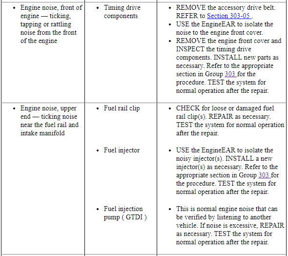
Fuel injector noise
A common source of an engine ticking noise can be related to the fuel injection pump Gasoline Turbocharged Direct Injection (GTDI) engine or the fuel injector(s). This is normal engine noise that can be verified by listening to another vehicle. If the injector noise is excessive or irregular, use the EngineEAR/ChassisEAR or stethoscope to isolate the noise to a specific fuel injector.
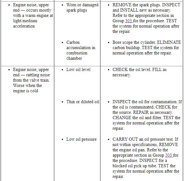
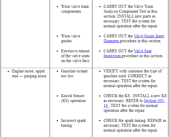
Upper end engine noise
A common source of upper end engine noise (ticking, knocking or rattle) include the camshaft(s) and valve train. Upper end engine noise can be determined using the EngineEAR/ChassisEAR or stethoscope on the valve cover bolts. If the noise is loudest from the valve cover bolts, then the noise is upper end. The EngineEAR/ChassisEAR or stethoscope can be used to further isolate the noise to the specific cylinder bank and cylinder. Removal of the valve covers will be required to pinpoint the source of the noise.
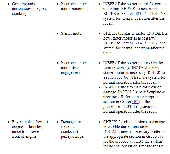
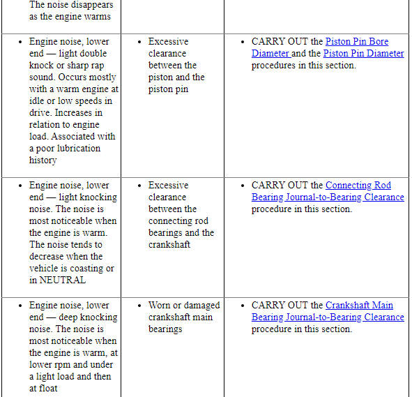
Lower end engine noise
A common source of lower end engine noise (ticking or knocking) include the crankshaft, connecting rod(s) and bearings. Lower end noises can be determined by using the oil pan or cylinder block lug bosses. If the noise is loudest from these areas, then the noise is lower end. If an engine noise is isolated to the lower end, some disassembly of the engine may be required to inspect for damage or wear.
Front of engine noise
A common source of noise from the front of the engine (squeal, chirp, whine or hoot) is the Front End Accessory Drive (FEAD) components. To isolate FEAD noise, carry out the Engine Accessory Test, refer to Section 100-04.
Some other noises from the front of the engine (ticking, tapping or rattle) may be internal to the engine. Use the EngineEAR/ChassisEAR or stethoscope on the engine front cover to determine if the noise is internal to the engine. Removal of the engine front cover may be necessary to inspect internal engine components.
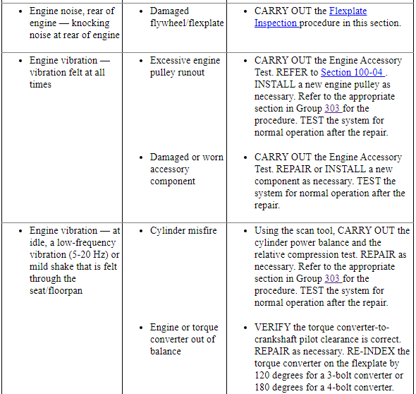
Rear of engine noise
A common source of noise from the rear of the engine (knocking) is the flywheel/flexplate. Inspection of the flywheel/flexplate will be necessary.
Some engines have timing drive components at the rear of the engine and may be the source of noise (ticking, knocking or rattle). Use the EngineEAR/ChassisEAR or stethoscope on the rear of the engine if the noise is suspected to be internal to the engine. Some disassembly of the engine may be required to inspect for damage or wear.
- After the noise is localized, note the characteristics of the noise, including type of noise, frequency and conditions when the noise occurs and GO to Symptom Chart - NVH.
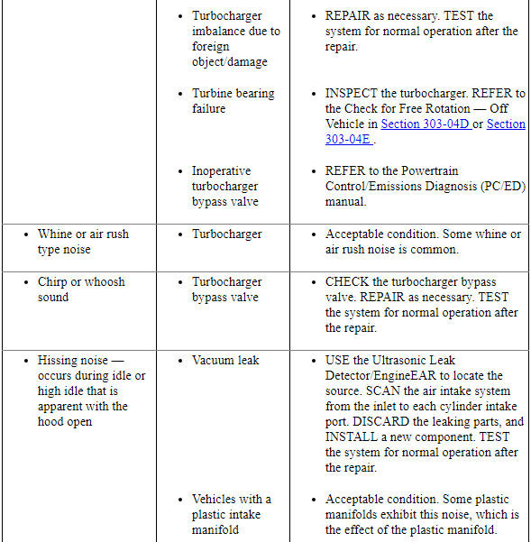
Turbocharger noise (Gasoline Turbocharged Direct Injection (GTDI) engine)
A common source of noise is the turbochargers. Some whine or air rush noise is an acceptable condition.
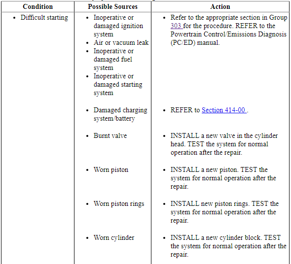
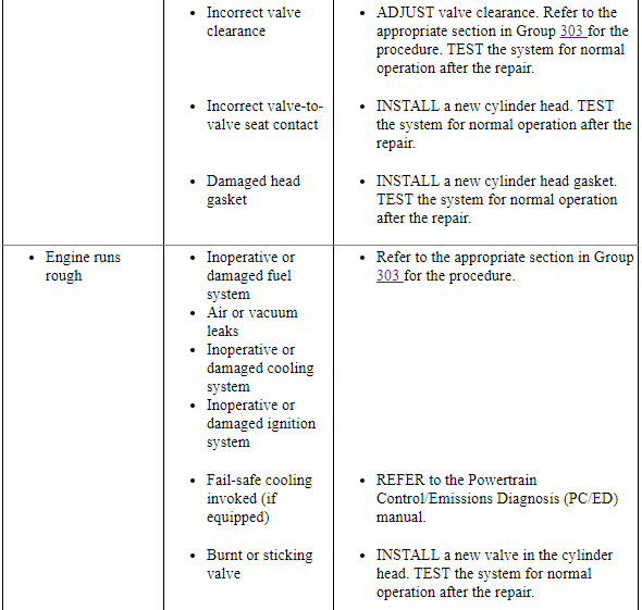
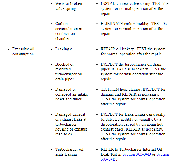
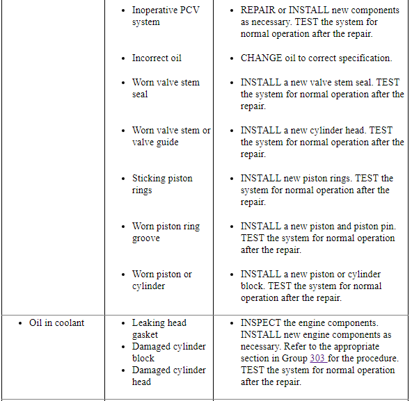
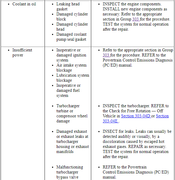
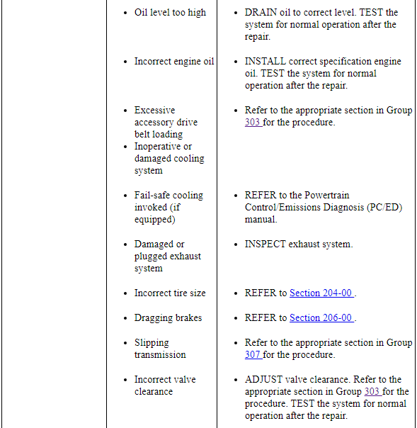
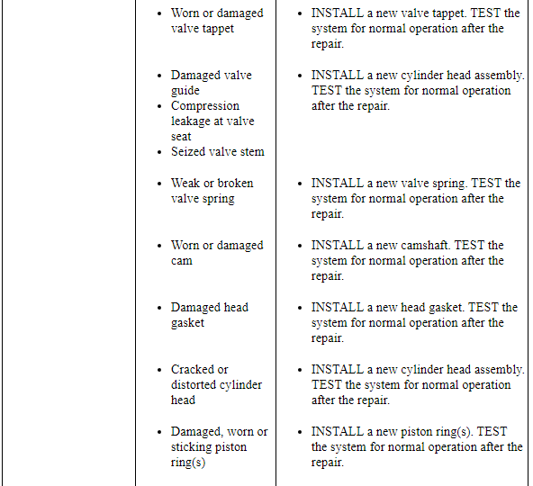
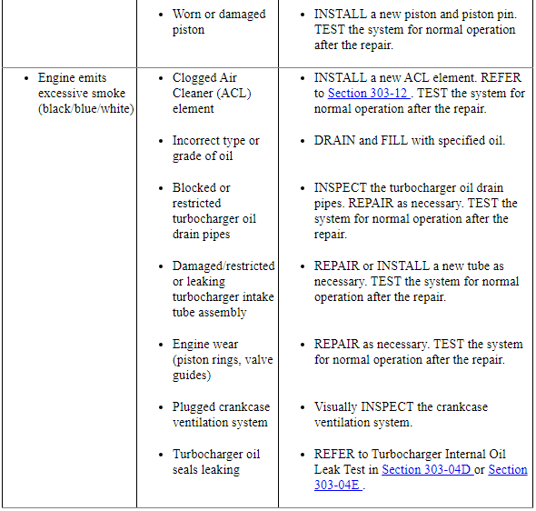
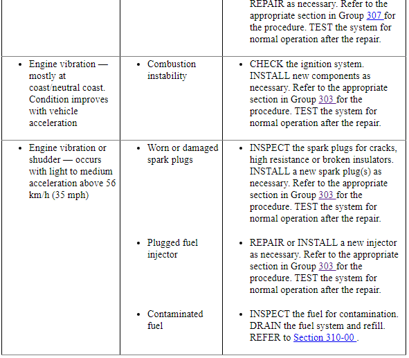
Symptom Chart - Engine Performance

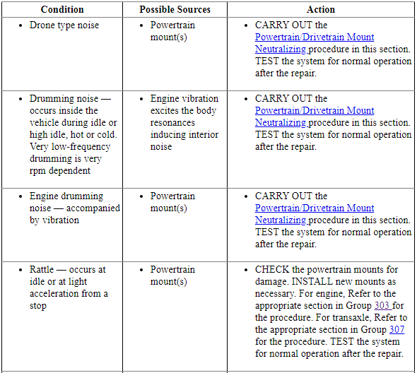
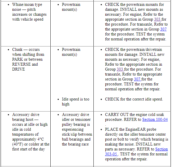
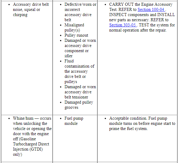
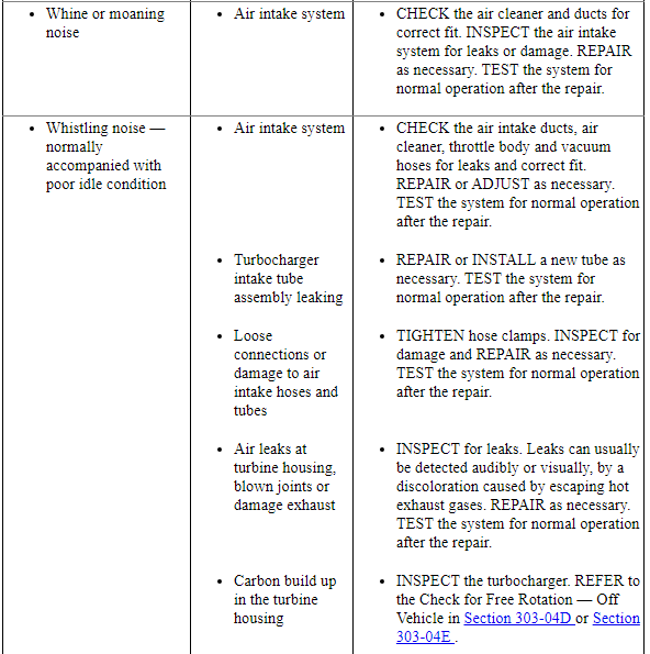
Symptom Chart - NVH
NOTE: NVH symptoms should be identified using the diagnostic tools that are available. For a list of these tools, an explanation of their uses and a glossary of common terms, refer to Section 100-04. Since it is possible that any one of multiple systems may be the cause of the symptom, it may be necessary to use a process of elimination type of diagnostic approach to pinpoint the responsible system. If this is not the causal system for the symptom, refer back to Section 100-04 for the next likely system and continue diagnosis.

Component Tests
The following component tests are used to diagnose engine concerns.
Engine Oil Leaks
NOTE: When diagnosing engine oil leaks, the source of the leak must be positively identified prior to repair. If the vehicle is driven extensively between adding the fluorescent additive and performing the leak test, fan air or wind can spread the leaking oil and make identifying the location of the leak difficult.
Prior to carrying out this procedure, clean the cylinder block, cylinder heads, valve covers, oil pan and flywheel with a suitable solvent to remove all traces of oil.
Engine Oil Leaks - Fluorescent Oil Additive Method
Use the 12 Volt Master UV Diagnostic Inspection Kit to carry out the following procedure for oil leak diagnosis.
- Add 29.6 ml (1 oz) of gasoline engine oil dye to a minimum of 0.47L (1/2 qt) and a maximum of 0.95L (1 qt) engine oil and fill through the engine oil fill. Thoroughly premix the gasoline engine oil dye or it will not have enough time to reach the crankcase, oil galleries and seal surfaces during this particular 15 minute test. The additive must be mixed well with oil and added through the oil fill. Check the level on the oil level indicator to determine what amount of oil to premix. If it is in the middle of the crosshatch area or below the full mark, use 0.95L (1 qt). If it is at the full mark, use 0.47L (1/2 qt).
- Run the engine for 15 minutes. Stop the engine and inspect all seal and gasket areas for leaks using the 12 Volt Master UV Diagnostic Inspection Kit. A clear bright yellow or orange area will identify the leak. For extremely small leaks, several hours may be required for the leak to appear.
- At the end of test, make sure the oil level is within the upper and lower oil indicator marks. Remove oil as necessary if it registers above the full mark.
Leakage Points - Underhood
Examine the following areas for oil leakage:
- Valve cover gaskets
- Cylinder head gaskets
- Oil cooler, if equipped
- Oil filter adapter
- Engine front cover
- Oil filter adapter and filter body
- Oil level indicator tube connection
- Engine Oil Pressure (EOP) switch
Leakage Points - Under Engine, With Vehicle on Hoist
Examine the following areas for oil leakage:
- Oil pan gaskets
- Oil pan sealer
- Engine front cover gasket
- Crankshaft front seal
- Crankshaft rear oil seal
- Oil filter adapter and filter body
- Oil cooler, if equipped
Leakage Points - With Transmission and Flywheel Removed
Examine the following areas for oil leakage:
- Crankshaft rear oil seal
- Rear main bearing cap parting line
- Flexplate mounting bolt holes (with flexplate installed)
- Pipe plugs at the end of oil passages
Oil leaks at crimped seams in sheet metal parts and cracks in cast or stamped parts can be detected when using the dye method.
Compression Test
- Make sure the oil in the crankcase is of the correct viscosity and at the correct level and that the battery is correctly charged. Operate the vehicle until the engine is at normal operating temperature. Turn the ignition switch to the OFF position, then remove all the spark plugs.
- Set the throttle plates in the wide-open position.
- Install a compression gauge in the No. 1 cylinder.
- Install an auxiliary starter switch in the starting circuit. With the ignition switch in the OFF position, and using the auxiliary starter switch, crank the engine a minimum of 5 compression strokes and record the highest reading. Note the approximate number of compression strokes necessary to obtain the highest reading.
- Repeat the test on each cylinder, cranking the engine approximately the same number of compression strokes.
Compression Test - 3.5L Engine Test Results
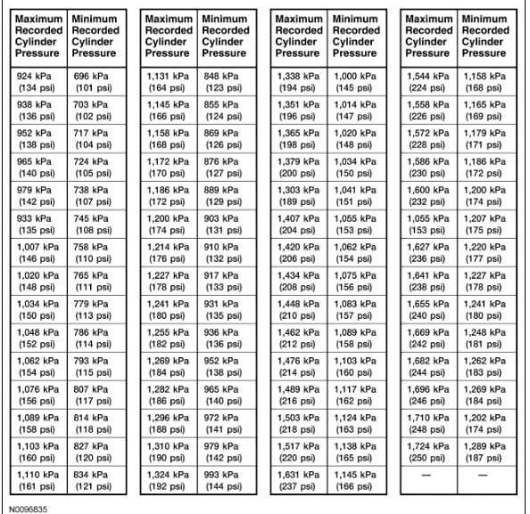
The indicated compression pressures are considered within specification if the lowest reading cylinder is at least 75% of the highest reading. Refer to the Compression Pressure Limit Chart.
If one or more cylinders reads low, squirt approximately one tablespoon of engine oil meeting Ford specification on top of the pistons in the low-reading cylinders. Repeat the compression pressure check on these cylinders.
Compression Test - 3.5L Gasoline Turbocharged Direct Injection (GTDI) Engine Test Results
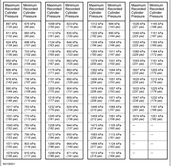
The indicated compression pressures are considered within specification if the lowest reading cylinder is at least 75% of the highest reading. Refer to the Compression Pressure Limit Chart.
If one or more cylinders reads low, squirt approximately one tablespoon of engine oil meeting Ford specification on top of the pistons in the low-reading cylinders. Repeat the compression pressure check on these cylinders.
Compression Test - Interpreting Compression Readings
- If compression improves considerably, piston rings are worn or damaged.
- If compression does not improve, valves are sticking or not seating correctly.
- If 2 adjacent cylinders indicate low compression pressures and squirting
oil on each piston does not increase compression, the head gasket may be
leaking between cylinders. Engine oil or coolant in cylinders could result
from this condition.
Use the Compression Pressure Limit Chart when checking cylinder compression so that the lowest reading is within 75% of the highest reading.
Cylinder Leakage Detection
When a cylinder produces a low reading, use of a cylinder leakage tester will be helpful in pinpointing the exact cause.
The leakage tester is inserted in the spark plug hole, the piston is brought up to Top Dead Center (TDC) on the compression stroke, and compressed air is admitted.
Once the combustion chamber is pressurized, the leakage tester gauge will read the percentage of leakage. Leakage exceeding 20% is excessive.
While the air pressure is retained in the cylinder, listen for the hiss of escaping air. A leak at the intake valve will be heard in the Throttle Body (TB). A leak at the exhaust valve can be heard at the tailpipe. Leakage past the piston rings will be audible at the PCV connection. If air is passing through a blown head gasket to an adjacent cylinder, the noise will be evident at the spark plug hole of the cylinder into which the air is leaking. Cracks in the cylinder block or gasket leakage into the cooling system may be detected by a stream of bubbles in the radiator.
Excessive Engine Oil Consumption
Nearly all engines consume oil, which is essential for normal lubrication of the cylinder bore walls and pistons and rings. Determining the level of oil consumption may require testing by recording how much oil is being added over a given set of miles.
Customer driving habits greatly influence oil consumption. Mileage accumulated during towing or heavy loading generates extra heat. Frequent short trips, stop-and-go type traffic or extensive idling, prevent the engine from reaching normal operating temperature. This prevents component clearances from reaching specified operating ranges.
The following diagnostic procedure may be utilized to determine internal oil consumption. Make sure that the concern is related to internal oil consumption, and not external leakage, which also consumes oil. Verify there are no leaks before carrying out the test. Once verified, the rate of internal oil consumption can be tested.
A new engine may require extra oil in the early stages of operation. Internal piston-to-bore clearances and sealing characteristics improve as the engine breaks in. Engines are designed for close tolerances and do not require break-in oils or additives. Use the oil specified in the Owner's Literature. Ambient temperatures may determine the oil viscosity specification. Verify that the correct oil is being used for the vehicle in the geographic region in which it is driven.
Basic Pre-checks
- For persistent complaints of oil consumption, interview the customer to determine the oil consumption characteristics. If possible, determine the brand and grade of oil currently in the oil pan. Look at the oil filter or oil-change station tags to determine if Ford-recommended maintenance schedules have been followed. Make sure that the oil has been changed at the specified mileage intervals. If vehicle mileage is past the first recommended drain interval, the OEM production filter should have been changed.
- Ask how the most current mileage was accumulated. That is, determine
whether the vehicle was driven under the following conditions:
- Extended idling or curbside engine operation
- Stop-and-go traffic or taxi operation
- Towing a trailer or vehicle loaded heavily
- Frequent short trips (engine not up to normal operating temperature)
- Excessive throttling or high engine-rpm driving
- Verify that there are no external leaks. If necessary, review the diagnostic procedure under Engine Oil Leaks in the Diagnosis and Testing portion of this section.
- Inspect the crankcase ventilation system for:
- disconnected hoses at the valve cover or TB.
- loose or missing valve cover fill cap.
- missing or incorrectly seated engine oil level indicator.
- incorrect or dirty PCV valve.
- a PCV valve grommet unseated in the valve cover (if so equipped).
- Inspect for signs of sludge. Sludge affects PCV performance and can plug or restrict cylinder head drainback wells. It can also increase oil pressure by restricting passages and reducing the drainback capability of piston oil control rings. Sludge can result from either excessive water ingestion in the crankcase or operation at extremely high crankcase temperatures.
- Inspect the air filter for dirt, sludge or damage. A hole in the filter element will allow unfiltered air to bypass into the air induction system. This can cause premature internal wear (engine dusting), allowing oil to escape past rings, pistons, valves and guides.
- If the engine is hot or was recently shut down, wait at least 5 minutes to allow the oil to drain back. Ask the customer if this requirement has been followed. Adding oil without this wait period can cause an overfill condition, leading to excessive oil consumption and foaming, which may cause engine damage.
- Make sure the oil level indicator (dipstick) is correctly and fully seated in the indicator tube. Remove the oil level indicator and record the oil level.
Detailed Pre-checks
- Check the thermostat opening temperature to make sure that the cooling system is operating at the specified temperature. If it is low, internal engine parts are not running at specified internal operating clearances.
- Verify the spark plugs are not oil saturated. Oil leaking into one or more cylinders will appear as an oil soaked condition on the plug. If a plug is saturated, a compression check may be necessary at the conclusion of the oil consumption test.
Oil Consumption Test
Once all of the previous conditions are met, carry out an oil consumption test.
- Drain the engine oil and remove the oil filter. Install a new manufacturer-specified oil filter. Make sure the vehicle is positioned on a level surface. Refill the oil pan to a level one liter (quart) less than the specified fill level, using manufacturer-specified oil.
- Run the engine for 3 minutes (if hot) or 10 minutes (if cold). Allow for a minimum 5-minute drainback period and then record the oil level shown on the oil level indicator. Place a mark on the backside of the oil level indicator noting the oil level location.
- Add the final one liter (quart) to complete the normal oil fill. Restart the engine and allow it to idle for 2 minutes. Shut the engine down.
- After a 5-minute drainback period, record the location of the oil level again. Mark the oil level indicator with the new oil level location. (Note: Both marks should be very close to the MIN-MAX upper and lower limits or the upper and lower holes on the oil level indicator. These marks will exactly measure the engine's use of oil, with a one quart differential between the new marks.) Demonstrate to the customer that the factory-calibrated marks on the oil level indicator are where the oil should fall after an oil change with the specified fill amount. Explain however, that this may vary slightly between MIN-MAX or the upper and lower holes on the oil level indicator.
- Record the vehicle mileage.
- Advise the customer that oil level indicator readings must be taken every 320 km (200 mi) or weekly, using the revised marks as drawn. Remind the customer that the engine needs a minimum 5-minute drainback for an accurate reading and that the oil level indicator must be firmly seated in the tube prior to taking the reading.
- When the subsequent indicator readings demonstrate a full liter (quart) has been used, record the vehicle mileage. The mileage driven between the 2 readings should not be less than 2,414 km (1,500 mi). The drive cycle the vehicle has been operated under must be considered when making this calculation. It may be necessary to have the customer bring the vehicle in for a periodic oil level indicator reading to closely monitor oil usage.
Post Checks, Evaluation and Corrective Action
- If test results indicate excessive oil consumption, carry out a cylinder compression test. The cylinder compression test should be carried out with a fully charged battery and all spark plugs removed. See the Compression Test Chart in this section for pressure range limits.
- Compression should be consistent across all cylinders. Refer to the Compression Testing portion of this section. If compression tested within the specifications found in this section, the excessive oil consumption may be due to wear on the valve guides, valves or valve seals.
- A cylinder leak detection test can be carried out using a cylinder leakage tester. This can help identify valves, piston rings, or worn valve guides/valve stems, inoperative valve stem seals or other related areas as the source of oil consumption.
NOTE: An oil-soaked appearance on the porcelain tips of the spark plugs also indicates excessive oil use. A typical engine with normal oil consumption will exhibit a light tan to brown appearance. See Spark Plug Analysis in this section for details. A single or adjoining, multiple cylinder leak can be traced by viewing the tips.
- If an internal engine part is isolated as the root cause, determine if the repair will exceed cost limits and proceed with a repair strategy as required.
- Once corrective action to engine is complete and verifying that all pre-check items were eliminated in the original diagnosis, repeat the Oil Consumption Test as described above and verify consumption results.
Intake Manifold Vacuum Test
Bring the engine to normal operating temperature. Connect the Vacuum/Pressure Tester to the intake manifold. Run the engine at the specified idle speed.
The vacuum gauge should read between 51-74 kPa (15-22 in-Hg) depending upon the engine condition and the altitude at which the test is conducted. Subtract 4.0193 kPa (1 in-Hg) from the specified reading for every 304.8 m (1,000 ft) of elevation above sea level.
The reading should be steady. If necessary, adjust the gauge damper control (where used) if the needle is fluttering rapidly. Adjust the damper until the needle moves easily without excessive flutter.
Intake Manifold Vacuum Test - Interpreting Vacuum Gauge Readings
A careful study of the vacuum gauge reading while the engine is idling will help pinpoint trouble areas. Always conduct other appropriate tests before arriving at a final diagnostic decision. Vacuum gauge readings, although helpful, must be interpreted carefully.
Most vacuum gauges have a normal band indicated on the gauge face.
The following are potential gauge readings. Some are normal; others should be investigated further.
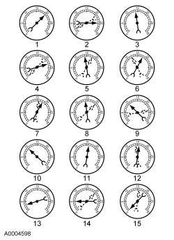
- NORMAL READING: Needle between 51-74 kPa (15-22 in-Hg) and holding steady.
- NORMAL READING DURING RAPID ACCELERATION AND DECELERATION: When the engine is rapidly accelerated (dotted needle), the needle will drop to a low reading (not to zero). When the throttle is suddenly released, the needle will snap back up to a higher than normal figure.
- NORMAL FOR HIGH-LIFT CAMSHAFT WITH LARGE OVERLAP: The needle will register as low as 51 kPa (15 in-Hg) but will be relatively steady. Some oscillation is normal.
- WORN RINGS OR DILUTED OIL: When the engine is accelerated (dotted needle), the needle drops to 0 kPa (0 in-Hg). Upon deceleration, the needle runs slightly above 74 kPa (22 in-Hg).
- STICKING VALVES: When the needle (dotted) remains steady at a normal vacuum but occasionally flicks (sharp, fast movement) down and back about 13 kPa (4 in-Hg), one or more valves may be sticking.
- BURNED OR WARPED VALVES: A regular, evenly-spaced, downscale flicking of the needle indicates one or more burned or warped valves. Insufficient valve clearance will also cause this reaction.
- POOR VALVE SEATING: A small but regular downscale flicking can mean one or more valves are not seating.
- WORN VALVE GUIDES: When the needle oscillates over about a 13 kPa (4 in-Hg) range at idle speed, the valve guides could be worn. As engine speed increases, the needle will become steady if guides are responsible.
- WEAK VALVE SPRINGS: When the needle oscillation becomes more violent as engine rpm is increased, weak valve springs are indicated. The reading at idle could be relatively steady.
- LATE VALVE TIMING: A steady but low reading could be caused by late valve timing.
- IGNITION TIMING RETARDING: Retarded ignition timing will produce a steady but somewhat low reading.
- INSUFFICIENT SPARK PLUG GAP: When spark plugs are gapped too close, a regular, small pulsation of the needle can occur.
- INTAKE LEAK: A low, steady reading can be caused by an intake manifold or throttle body gasket leak.
- BLOWN HEAD GASKET: A regular drop of fair magnitude can be caused by a blown head gasket or warped cylinder head-to-cylinder block surface.
- RESTRICTED EXHAUST SYSTEM: When the engine is first started and is idled, the reading may be normal, but as the engine rpm is increased, the back pressure caused by a clogged muffler, kinked tailpipe or other concerns will cause the needle to slowly drop to 0 kPa (0 in-Hg). The needle then may slowly rise. Excessive exhaust clogging will cause the needle to drop to a low point even if the engine is only idling.
- When vacuum leaks are indicated, search out and correct the cause. Excess air leaking into the system will upset the fuel mixture and cause concerns such as rough idle, missing on acceleration or burned valves. If the leak exists in an accessory unit such as the power brake booster, the unit will not function correctly. Always fix vacuum leaks.
Oil Pressure Test
- Disconnect and remove the oil pressure switch from the engine.
- Connect the engine Oil Pressure Gauge to the oil pressure switch oil galley port.
- Run the engine until normal operating temperature is reached.
- Run the engine at the specified rpm and record the gauge reading.
- The oil pressure should be within specifications; refer to the specification chart in the appropriate engine section.
- If the pressure is not within specification, check the following
possible sources:
- Insufficient oil
- Oil leakage
- Worn or damaged oil pump
- Oil pump screen cover and tube
- Excessive main bearing clearance
- Excessive connecting rod bearing clearance
- Chain tensioner leak
- Piston squirter stuck open
- Oil pump relief valve stuck open
- Improper oil grade
Valve Train Analysis
The following component tests are used to diagnose valve train concerns.
Valve Train Analysis - Engine Off, Valve Cover Removed
Check for damaged or severely worn parts and correct assembly. Make sure correct parts are used with the static engine analysis as follows.
Valve Train Analysis - Camshafts and Valve Tappets
- Check for broken or damaged parts.
- Check for loose mounting bolts on camshaft caps.
- Check for worn or damaged valve tappets.
Valve Train Analysis - Valve Springs, Valve Tappets Removed
- Check for broken or damaged parts.
Valve Train Analysis - Valve Spring Retainer and Valve Spring Retainer Keys, Valve Tappets Removed
- Check for correct seating of the valve spring retainer key on the valve stem and in valve spring retainer.
- Check for correct seating on the valve stem.
Valve Train Analysis - Valves and Cylinder Head, Valve Tappets Removed
- Check for plugged oil drain-back holes.
- Check for worn or damaged valve tips.
- Check for missing or damaged valve stem seals or guide-mounted valve stem seal.
- Check for missing or worn valve spring seats.
Valve Train Analysis - Camshaft Lobe Lift
Check the lift of each camshaft lobe in consecutive order and make a note of the readings.
- Remove the spark plugs. Refer to the appropriate section in Group 303 for the procedure.
- Install the Dial Indicator Gauge with Holding Fixture so the rounded tip of the Dial Indicator Gauge is on top of the camshaft lobe and on the same plane as the valve tappet.
- Rotate the crankshaft using a breaker bar and socket attached to the crankshaft pulley retainer bolt. Rotate the crankshaft until the base circle of the camshaft lobe is reached.
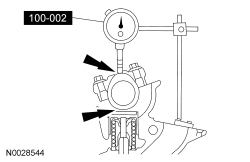
- Zero the Dial Indicator Gauge. Continue to rotate the crankshaft until the high-lift point of the camshaft lobe is in the fully-raised position (highest indicator reading).
- To check the accuracy of the original Dial Indicator Gauge reading, continue to rotate crankshaft until the base circle is reached. The Dial Indicator Gauge reading should be zero. If zero reading is not obtained, repeat Steps 1 through 6.
- If the lift on any lobe is below specified service limits, install a new camshaft and camshaft valve tappets.
- Install the spark plugs. Refer to the appropriate section in Group 303 for the procedure.

 General Procedures
Camshaft Bearing Journal Diameter
NOTE: Refer to the appropriate Section 303-01 for the specification.
Measure each camshaft journal diameter in 2 directions.
Camshaft Journal to Bearing ...
Other materials:
Booster seats
WARNING: Never place, or allow a child to place, the shoulder
belt under a child’s arm or behind the back because it reduces
the protection for the upper part of the body and may increase the risk
of injury or death in a crash.
Use a belt-positioning booster seat for children who have outgrown ...
Anti-Theft - Perimeter
DESCRIPTION AND OPERATION
Anti-Theft - Without Intelligent Access (IA)
Overview
The perimeter alarm system deters unauthorized entry to the vehicle by
sounding the horn and flashing all the turn signals and interior courtesy lamps
when an unauthorized entry occurs. The horn and lamps activate for ...
Diagnosis and Testing
Charging System
Special Tool(s)
DTC Charts
Diagnostics in this manual assume a certain skill level and knowledge of
Ford-specific diagnostic practices. REFER to Diagnostic Methods in Section
100-00 for more information.
NOTE: The BCM utilizes
a 5-character DTC followe ...
