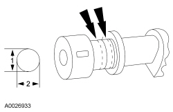
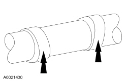
Camshaft Bearing Journal Diameter
NOTE: Refer to the appropriate Section 303-01 for the specification.
- Measure each camshaft journal diameter in 2 directions.
Camshaft Journal to Bearing Clearance - OHC Engines
NOTE: Refer to the appropriate Section 303-01 for the specification.
- NOTE: The camshaft journals must meet specifications before
checking camshaft journal clearance.
Measure each camshaft bearing in 2 directions.
- Subtract the camshaft journal diameter from the camshaft bearing diameter.
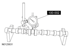
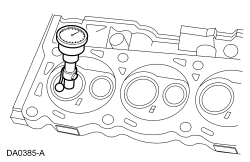
Camshaft End Play - OHC Engines
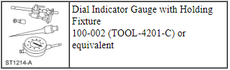
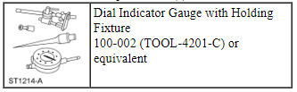
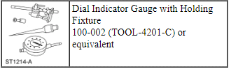
Special Tool(s)
NOTE: Refer to the appropriate Section 303-01 for the specification.
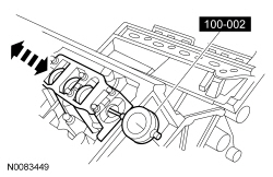
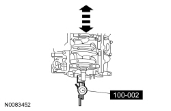
- Using the Dial Indicator Gauge with Holding Fixture, measure the camshaft end play.
- Position the camshaft to the rear of the cylinder head.
- Zero the Dial Indicator Gauge.
- Move the camshaft to the front of the cylinder head. Note and record the
camshaft end play.
- If camshaft end play exceeds specifications, install a new camshaft and recheck end play.
- If camshaft end play exceeds specification after camshaft installation, install a new cylinder head.
Camshaft Surface Inspection
- Inspect camshaft lobes for pitting or damage in the contact area. Minor pitting is acceptable outside the contact area.
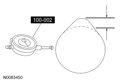
Camshaft Lobe Lift
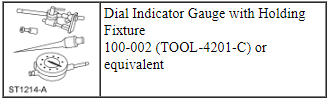
Special Tool(s)
NOTE: Refer to the appropriate Section 303-01 for the specification.
- Use the Dial Indicator Gauge with Holding Fixture to measure camshaft
intake/exhaust lobe lift.
- Rotate the camshaft and subtract the lowest Dial Indicator Gauge reading from the highest Dial Indicator Gauge reading to figure the camshaft lobe lift.
Camshaft Runout
Special Tool(s)
NOTE: Refer to the appropriate Section 303-01 for the specification.
- NOTE: Camshaft journals must be within specifications before
checking runout.
Using the Dial Indicator Gauge with Holding Fixture, measure the camshaft runout.
- Camshaft must be supported on the first and last camshaft bearing journal.
- Rotate the camshaft and subtract the lowest Dial Indicator Gauge reading from the highest Dial Indicator Gauge reading.
Crankshaft Main Bearing Journal Diameter
NOTE: Refer to the appropriate Section 303-01 for the specification.
- Measure each of the crankshaft main bearing journal diameters in at least 2 directions.
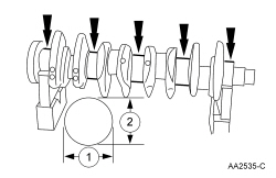
Crankshaft Main Bearing Journal Taper and Out-of-Round
NOTE: Refer to the appropriate Section 303-01 for the specification.
- Measure each of the crankshaft main bearing journal diameters in at least 2 directions at each end of the main bearing journal.

Crankshaft Main Bearing Journal-to-Bearing Clearance
NOTE: Refer to the appropriate Section 303-01 for the specification.
NOTE: Crankshaft main bearing journals must be within specifications before checking journal clearance.
- Remove the crankshaft main bearing caps and crankshaft main bearing.
- Lay a piece of Plastigage across the face of each crankshaft main bearing surface.
- NOTE: Do not turn the crankshaft while carrying out this
procedure.
Install and remove the crankshaft main bearing cap.
- Verify the crankshaft journal clearance.
Crankshaft End Play
Special Tool(s)
NOTE: Refer to the appropriate Section 303-01 for the specification.
- Install the Dial Indicator Gauge with Holding Fixture.
- Position the crankshaft to the rear of the cylinder block.
- Zero the Dial Indicator Gauge.
- Move the crankshaft to the front of the cylinder block. Note and record the crankshaft end play.
Connecting Rod Bearing Journal Taper and Out-of-Round
NOTE: Refer to the appropriate Section 303-01 for the specification.
- Measure the crankshaft connecting rod journal diameters in 2 directions perpendicular to one another at each end of the connecting rod journal. The difference in the measurements from one end to the other is the taper. Verify measurement is within the wear limit.
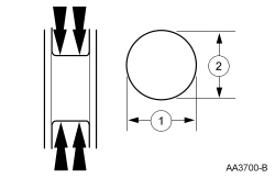
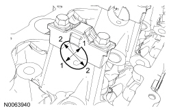
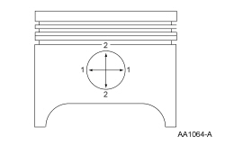
Cylinder Bore Taper
NOTE: Refer to the appropriate Section 303-01 for the specification.
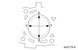
- Measure the cylinder bore at the top, middle and bottom of piston ring travel in 2 directions as indicated. Verify the cylinder bore is within the wear limit. The difference indicates the cylinder bore taper. If the cylinder bore taper does not meet specification, bore the cylinder to the next oversize limit.
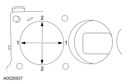
Cylinder Bore Out-of-Round
NOTE: Refer to the appropriate Section 303-01 for the specification.
- Measure the cylinder bore in 2 directions. The difference is the out-of-round.
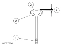
Piston Inspection
Special Tool(s)
NOTICE: Do not use a caustic cleaning solution or a wire brush to clean the pistons or damage can occur.
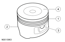
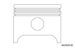
- Clean and inspect the (1) ring lands, (2) skirts, (3) pin bosses and the (4) tops of the pistons. If wear marks, scores or glazing is found on the piston skirt, check for a bent or twisted connecting rod.
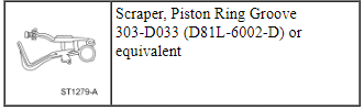
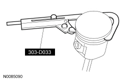
- Use the Piston Ring Groove Scraper to clean the piston ring grooves.
- Make sure the oil ring holes are clean.
Piston Pin Bore Diameter
NOTE: Refer to the appropriate Section 303-01 for the specification.
- NOTE: Piston and piston pins are a matched set and should not be
interchanged.
Measure the piston pin bore diameter in 2 directions on each side. Verify the diameter is within specification.
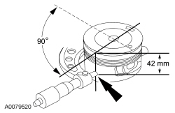
Piston Diameter
NOTE: Refer to the appropriate Section 303-01 for the specification.
- Measure the piston diameter 90 degrees from the piston pin and 42 mm (1.65 in) down from the top of the piston at the point indicated.
Piston To Cylinder Bore Clearance
NOTE: Refer to the appropriate Section 303-01 for the specification.
- Subtract the piston diameter from the cylinder bore diameter to find the piston-to-cylinder bore clearance.
Piston Selection
NOTE: The cylinder bore must be within the specifications for taper and out-of-round before fitting a piston.
- Select a piston size based on the cylinder bore.

- NOTE: For precision fit, new pistons are divided into 3
categories within each size range based on their relative position within
the range. A paint spot or specific size grade on a new piston indicates the
position within the size range.
Choose the piston with the correct paint color or specific size grade.
- Refer to the appropriate section in Group 303 for the procedure.
Piston Ring End Gap
Special Tool(s)
NOTICE: Use care when fitting piston rings to avoid possible damage to the piston ring or the cylinder bore.
NOTE: Piston rings should not be transferred from one piston to another.
NOTE: Refer to the appropriate Section 303-01 for the specification.
NOTE: The cylinder bore must be within specification for taper and out-of-round.
- Use a piston without rings to push a piston ring in a cylinder to the bottom of ring travel.
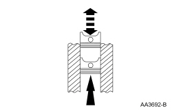
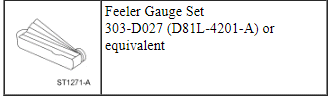
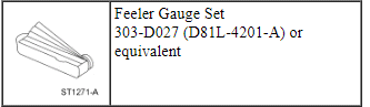
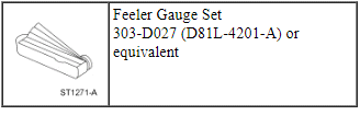
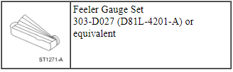
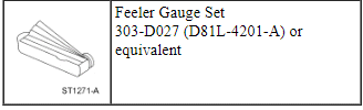
- Use the Feeler Gauge Set to measure the top piston ring end gap and the second piston ring end gap.
Piston Ring-to-Groove Clearance
Special Tool(s)
NOTE: Refer to the appropriate Section 303-01 for the specification.
- Inspect the piston for ring land damage or accelerated wear.
- Using the Feeler Gauge Set, measure the piston ring-to-groove clearance.
Piston Pin Diameter
NOTE: Refer to the appropriate Section 303-01 for the specification.
- Measure the piston pin diameter in 2 directions at the points shown. Verify the diameter is within specification.
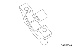
Connecting Rod Cleaning
NOTICE: Do not use a caustic cleaning solution or damage to connecting rods can occur.
- NOTE: The connecting rod large end is a matched set. The
connecting rod cap must be installed on the original connecting rod in the
original position. Do not reverse the cap. Parts are not interchangeable.
Mark and separate the parts and clean with solvent. Clean the oil passages.
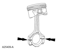
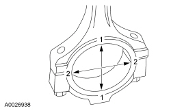
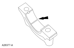
Connecting Rod Large End Bore
NOTE: Refer to the appropriate Section 303-01 for the specification.
- Tighten the bolts to specification, then measure the bore in 2 directions. The difference is the connecting rod bore out-of-round. Verify the out-of-round is within specification.
Connecting Rod Bushing Diameter
NOTE: Refer to the appropriate Section 303-01 for the specification.
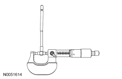
- Use a telescoping gauge to determine the ID of the connecting rod bushing, if equipped.
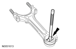
- Measure the telescoping gauge with a micrometer. Verify the diameter is within specification.
Connecting Rod Bend
Special Tool(s)
NOTE: Refer to the appropriate Section 303-01 for the specification.
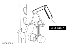
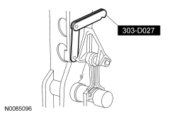
- Using the Feeler Gauge Set, measure the connecting rod bend on a suitable alignment fixture. Follow the instructions of the fixture manufacturer. Verify the bend measurement is within specification.
Connecting Rod Twist
Special Tool(s)
NOTE: Refer to the appropriate Section 303-01 for the specification.
- Using the Feeler Gauge Set, measure the connecting rod twist on a suitable alignment fixture. Follow the instructions of the fixture manufacturer. Verify the measurement is within specification.
Connecting Rod Bearing Journal-to-Bearing Clearance
NOTE: Refer to the appropriate Section 303-01 for the specification.
NOTE: The crankshaft connecting rod journals must be within specifications to check the connecting rod bearing journal clearance.
- Remove the connecting rod bearing cap.
- Position a piece of Plastigage across the bearing surface.
- NOTE: Do not turn the crankshaft during this step.
Install and tighten to specifications, then remove the connecting rod bearing cap.
- Measure the Plastigage to get the connecting rod bearing journal clearance. The Plastigage should be smooth and flat. A changing width indicates a tapered or damaged connecting rod or connecting rod bearing.
Connecting Rod to Crankshaft Side Clearance
Special Tool(s)
NOTE: Refer to the appropriate Section 303-01 for the specification.
- Using the Feeler Gauge Set, measure the clearance between the connecting rod and the crankshaft. Verify the measurement is within specification.
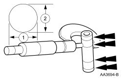
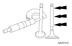
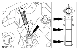
Valve Stem Diameter
NOTE: Refer to the appropriate Section 303-01 for the specification.
- Measure the diameter of each intake and exhaust valve stem at the points shown. Verify the diameter is within specification.
Valve Inspection
- Inspect the following valve areas:
- The end of the stem for grooves or scoring.
- The valve face and the edge for pits, grooves or scores.
- The valve head for signs of burning, erosion, warpage and cracking.
- The valve margin for wear.
Valve Guide Inner Diameter
NOTE: Refer to the appropriate Section 303-01 for the specification.
- NOTE: Valve guides tend to wear in an hourglass pattern. The ball
gauge can be inserted into the combustion chamber side of the valve guide,
if necessary.
Use a ball gauge to determine the inside diameter of the valve guides in 2 directions at the top, middle and bottom of the valve guide.
- Measure the ball gauge with a micrometer.
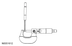
- If the valve guide is not within specifications, install a new cylinder head assembly.
Valve Stem to Valve Guide Clearance
Special Tool(s)
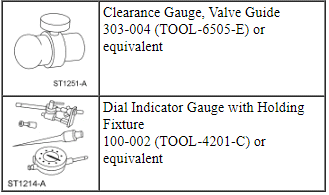
NOTE: Refer to the appropriate Section 303-01 for the specification.
NOTE: The valve stem diameter must be within specifications before checking valve stem-to-valve guide clearance.
- NOTE: If necessary, use a magnetic base.
Install a Valve Guide Clearance Gauge on the valve stem and install a Dial Indicator Gauge with Holding Fixture. Lower the valve until the clearance gauge contacts the upper surface of the valve guide.
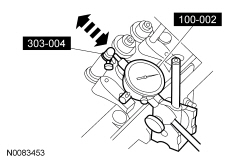
- Move the Valve Guide Clearance Gauge toward the Dial Indicator Gauge with Holding Fixture and zero the Dial Indicator Gauge. Move the Valve Guide Clearance Gauge away from the Dial Indicator Gauge with Holding Fixture and note the reading. The reading will be DOUBLE the valve stem-to-valve guide clearance.
Valve Spring Installed Length
NOTE: Refer to the appropriate Section 303-01 for the specification.
- Measure the installed length of each valve spring.
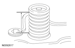
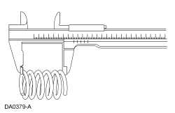
Valve Spring Free Length
NOTE: Refer to the appropriate Section 303-01 for the specification.
- Measure the free length of each valve spring.
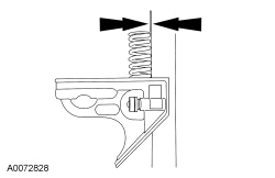
Valve Spring Squareness
- Measure the out-of-square on each valve spring.
- Turn the valve spring and observe the space between the top of the valve spring and the square.
Valve Spring Strength
Special Tool(s)
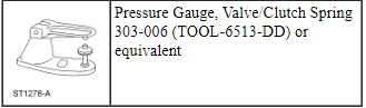
NOTE: Refer to the appropriate Section 303-01 for the specification.
- Use the Valve/Clutch Spring Pressure Gauge to check the valve spring for correct strength at the specified valve spring length.
Valve Seat Inspection
Valve and Seat Refacing Measurements
NOTE: Refer to the appropriate Section 303-01 for the specification.
NOTE: After grinding valves or valve seats, check valve clearance.
- Check the valve head and seat.
- Check valve angles.
- Check margin width.
- Be sure margin width is within specification.
- Inspect for abnormalities on the valve face and seat. Install a new cylinder head assembly if abnormalities are found.
Valve Seat Width
NOTE: Refer to the appropriate Section 303-01 for the specification.
- Measure the valve seat width. If necessary, grind the valve seat to
specification.
- Measure the intake valve seat width.
- Measure the exhaust valve seat width.
- Recheck the valve spring installed length after the seats have been ground, and shim the valve springs as necessary to achieve the correct installed spring length.
- Depending on the engine, check the valve lash. Refer to General Procedures in Section 303-01.
Valve Seat Runout
NOTE: Refer to the appropriate Section 303-01 for the specification.
- Use a valve seat runout gauge to check valve seat runout.
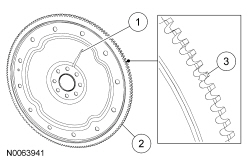
Flexplate Inspection
- Inspect the flexplate for:
- any cracks.
- worn ring gear teeth.
- chipped or cracked ring gear teeth.
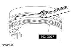
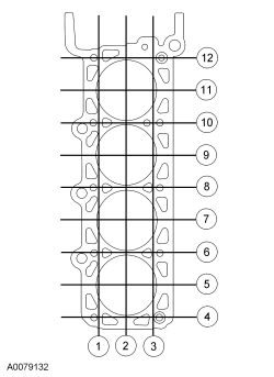
Cylinder Head Distortion
Special Tool(s)
NOTE: Refer to the appropriate Section 303-01 for the specification.
- NOTE: Make sure all cylinder head surfaces are clear of any
gasket material, silicone sealant, oil and coolant. The cylinder head
surface must be clean and dry before running a flatness check.
NOTE: Use a Straightedge that is calibrated by the manufacturer to be flat within 0.005 mm (0.0002 in) per running foot of length, such as Snap-On GA438A or equivalent. For example, if the Straightedge is 61 cm (24 in) long, the machined edge must be flat within 0.010 mm (0.0004 in) from end to end.
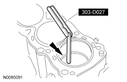
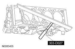
Using a Straightedge and a Feeler Gauge Set, inspect the cylinder head for flatness in the sequence shown.
Cylinder Block Distortion
Special Tool(s)
NOTE: Refer to the appropriate Section 303-01 for the specification.
- NOTE: Use a Straightedge that is calibrated by the manufacturer
to be flat within 0.005 mm (0.0002 in) per running foot of length, such as
Snap-On GA438A or equivalent. For example, if the Straightedge is 61 cm (24
in) long, the machined edge must be flat within 0.010 mm (0.0004 in) from
end to end.
Use a Straightedge and a Feeler Gauge Set to inspect the cylinder block for flatness.
Cylinder Bore Cleaning
Material
- NOTICE: If these procedures are not followed, rusting of the
cylinder bores may occur.
Clean the cylinder bores with soap or detergent and water.
- Thoroughly rinse with clean water and wipe dry with a clean, lint-free cloth.
- Use a clean, lint-free cloth and lubricate the cylinder bores.
- Use clean engine oil meeting Ford specification.
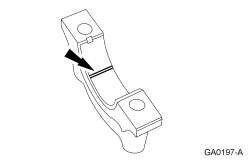
Bearing Inspection
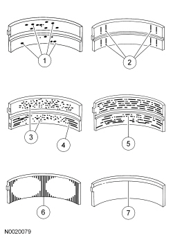
- Inspect bearings for the following defects:
- Cratering - fatigue failure
- Spot polishing - incorrect seating
- Imbedded dirty engine oil
- Scratching - dirty engine oil
- Base exposed - poor lubrication
- Both edges worn - journal damaged
- One edge worn - journal tapered or bearing not seated
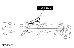
Exhaust Manifold Cleaning and Inspection
Special Tool(s)
- Clean the exhaust manifold using a suitable solvent. Use a plastic scraping tool to clean the gasket sealing surfaces.
- NOTE: New exhaust manifold gaskets, studs, nuts and/or bolts must
be installed when an exhaust manifold is serviced.
NOTE: Use a Straightedge that is calibrated by the manufacturer to be flat within 0.005 mm (0.0002 in) per running foot of length, such as Snap-On GA438A or equivalent. For example, if the Straightedge is 61 cm (24 in) long, the machined edge must be flat within 0.010 mm (0.0004 in) from end to end.
Using the Straightedge and a Feeler Gauge Set, check the exhaust manifold sealing surface for warpage. If the warpage is greater than 0.76 mm (0.0299 in), install a new exhaust manifold.
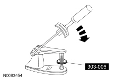
Core Plug Replacement
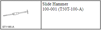
Special Tool(s)
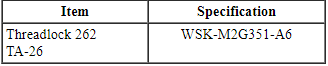
Material
All core plugs
- NOTE: Cylinder block core plug shown, cylinder head core plug
similar.
Use the Slide Hammer and a freeze plug remover to remove the core plug.
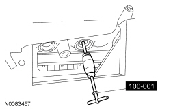
- NOTE: Oversize plugs are identified by the OS stamped in the flat
located on the cup side of the plug.
Inspect the core plug bore for any damage that would interfere with the correct sealing of the plug. If the core plug bore is damaged, bore for the next oversize plug.
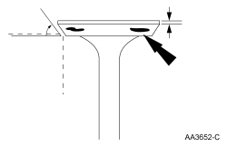
Cup-type
- NOTICE: Use care during this procedure so as not to disturb or
distort the cup sealing surface.
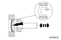
NOTE: When installed, the flanged edge must be below the chamfered edge of the bore to effectively seal the bore.
Coat the cup-type core plug and bore lightly with sealant and install the core plug using a freeze plug installer.
Expansion-type
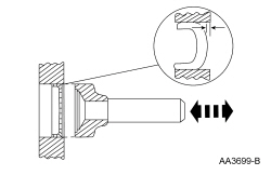
- NOTICE: Do not contact the crown when installing an
expansion-type core plug. This could expand the plug before seating and
result in leakage.
Coat the expansion-type core plug and bore lightly with sealant and install the core plug using a freeze plug installer.
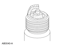
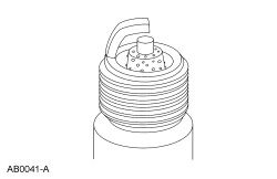
Spark Plug Inspection
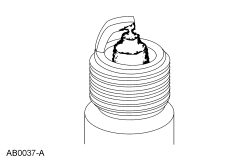
- Inspect the spark plug for a bridged gap.
- Check for deposit build-up closing the gap between the electrodes. Deposits are caused by oil or carbon fouling.
- Install a new spark plug.
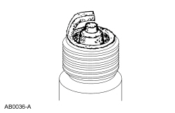
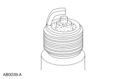
- Check for oil fouling.
- Check for wet, black deposits on the insulator shell bore electrodes, caused by excessive oil entering the combustion chamber through worn rings and pistons, excessive valve-to-guide clearance or worn or loose bearings.
- Correct the oil leak concern.
- Install a new spark plug.
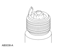
- Inspect for carbon fouling. Look for black, dry, fluffy carbon deposits
on the insulator tips, exposed shell surfaces and electrodes, caused by a
spark plug with an incorrect heat range, dirty air cleaner, too rich a fuel
mixture or excessive idling.
- Install new spark plugs.
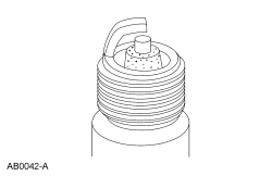
- Inspect for normal burning.
- Check for light tan or gray deposits on the firing tip.
- Inspect for pre-ignition, identified by melted electrodes and a possibly
damaged insulator. Metallic deposits on the insulator indicate engine
damage. This may be caused by incorrect ignition timing, wrong type of fuel
or the unauthorized installation of a heli-coil insert in place of the spark
plug threads.
- Install a new spark plug.
- Inspect for overheating, identified by white or light gray spots and a
bluish-burnt appearance of electrodes. This is caused by engine overheating,
wrong type of fuel, loose spark plugs, spark plugs with an incorrect heat
range, low fuel pump pressure or incorrect ignition timing.
- Install a new spark plug.
- Inspect for fused deposits, identified by melted or spotty deposits
resembling bubbles or blisters. These are caused by sudden acceleration.
- Install new spark plugs.
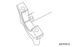
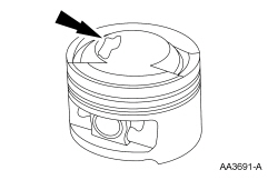
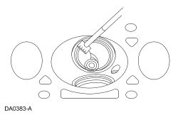
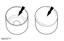
Valve Tappet Inspection
- Inspect the valve tappet for damage, especially in the indicated areas. If any damage is evident, inspect the camshaft lobes and valves for damage. Install new components as necessary.
Powertrain/Drivetrain Mount Neutralizing
NOTE: Refer to the appropriate section and procedure for special instructions on loosening and tightening mount fasteners.
- With the vehicle in NEUTRAL, position it on a hoist. For additional information, refer to Section 100-02.
- Loosen, but do not remove, the powertrain/drivetrain mount fasteners.
- Lower the vehicle.
- NOTICE: Do not twist or strain the powertrain/drivetrain
mounts or damage to the mounts may occur.
Start the vehicle and move it in forward 0.6-1.2 m (2-4 ft). Then move the vehicle in reverse the same distance.
- Raise and support the vehicle.
- Tighten the powertrain/drivetrain mount fasteners.
- Lower the vehicle.
- Test the system for normal operation.
 Specifications, Description and Operation, Diagnosis and Testing
SPECIFICATIONS
Material
DESCRIPTION AND OPERATION
Engine
NOTICE: When repairing engines, all parts must be contamination
free. If contamination/foreign material is present when repairing an eng ...

Other materials:
Fuel consumption
Filling the Tank
The advertised capacity is the indicated capacity and the empty reserve
combined. Indicated capacity is the difference in the amount of fuel in a
full tank and a tank when the fuel gauge indicates empty. Empty reserve
is the amount of fuel in the tank after the fuel gauge indica ...
Air filter(s)
WARNING: To reduce the risk of vehicle damage and/or personal
burn injuries, do not start your engine with the air cleaner
removed and do not remove it while the engine is running.
When changing the air filter element, use only the air filter element
listed. Refer to Motorcraft® Part Numbers in ...
Power seats
WARNING: Never adjust the driver’s seat or seat back when the
vehicle is moving.
WARNING: Before returning the seat back to its original
position, make sure that cargo or any objects are not trapped
behind the seat back.
Note: On vehicles with memory seats, to prevent damage to the seat,
t ...
