SPECIFICATIONS
Torque Specifications
DESCRIPTION AND OPERATION
Airbag and Safety Belt Pretensioner Supplemental Restraint System (SRS)
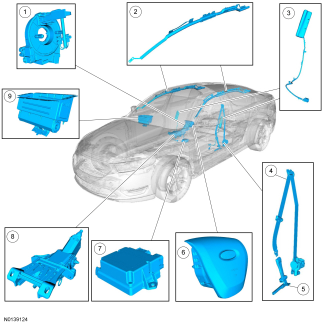
Air Bag and Safety Belt Pretensioner SRS Components (Illustration 1 of 2)
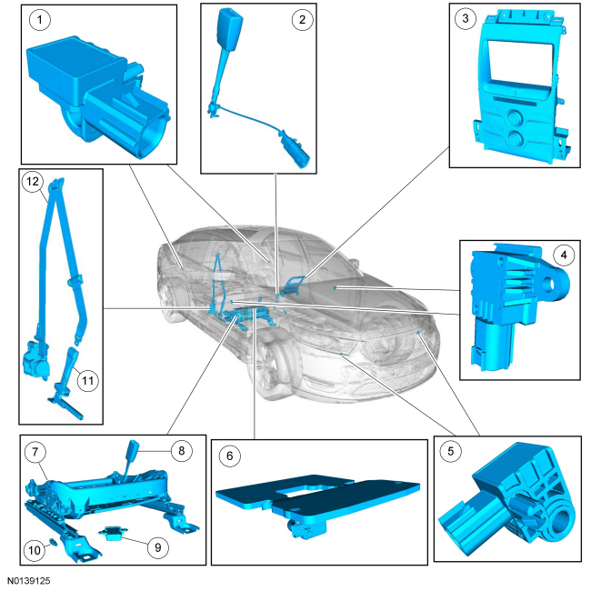
Air Bag and Safety Belt Pretensioner SRS Components (Illustration 2 of 2)
Overview
The RCM continually receives and monitors inputs from the OCSM and various other hard-wired switches and sensors. If the RCM detects a sudden vehicle deceleration and/or lateral deceleration based on the information received from the various sensors, and determines that deployment is necessary, the RCM applies voltage and current to deploy the appropriate SRS components.
System Operation
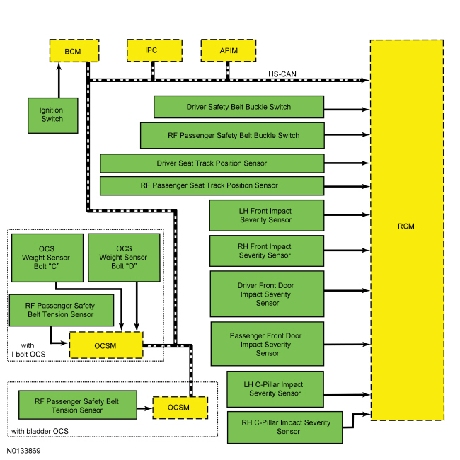
System Diagram - SRS Inputs
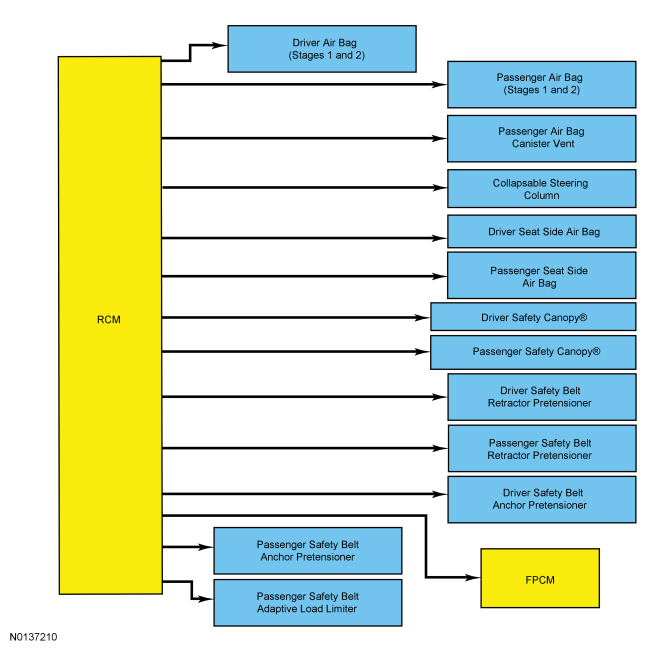
System Diagram - SRS Outputs
Network Message Chart - SRS
Module Network Input Messages - RCM
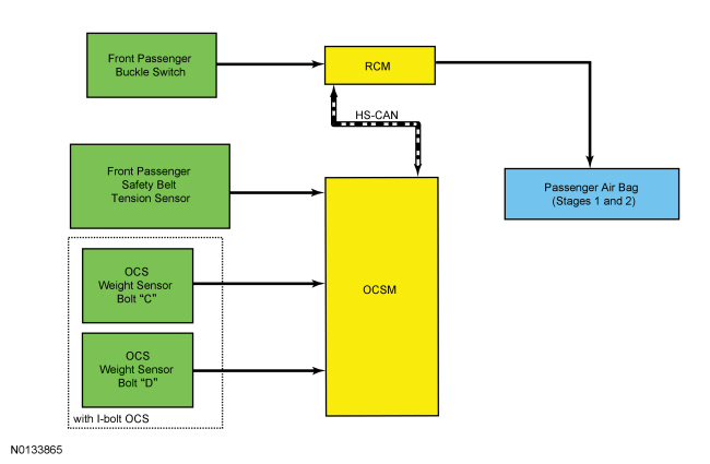
System Diagram - OCS
Network Message Chart - OCS
Module Network Input Messages - OCSM
SRS
The SRS is controlled by the RCM, which continually monitors various inputs. When these inputs indicate a frontal or side crash, the RCM may deploy some components, based upon the severity of the crash and the sensor inputs. Refer to the System Diagram - SRS to view the SRS inputs and outputs.
Although some deployable devices may not have activated for all occupants during a crash, it does not mean that something is wrong with the SRS.
The RCM performs a self-test of the complete SRS during each startup. During normal operation, the IPC illuminates the air bag warning indicator continuously for 6 seconds. If the SRS is free of faults, the air bag warning indicator turns off and remains off. If a SRS fault exists, the air bag warning indicator illuminates and remains illuminated for the rest of the ignition cycle. The RCM communicates to the IPC via the HS-CAN. The IPC illuminates the air bag warning indicator based on messaging from the RCM or if there is no communication between the RCM and IPC. In addition to the self-test at start up, the RCM continuously monitors all of its SRS components and circuitry for correct operation.
Air Bag Module Second Stage Deployment Check
The driver and passenger front air bags each have 2 deployment stages. After an air bag module deployment, it is possible that stage 1 has deployed and stage 2 has not. If a front air bag module has deployed, the front air bag module must be remotely deployed using the appropriate air bag disposal procedure. For information on driver air bag module and/or passenger air bag module remote deployment, refer to Pyrotechnic Device Disposal in this section.
Air Bag Warning Indicator
The air bag warning indicator:
- is located in the IPC and proves out by lighting for 6 seconds and then turning off.
- flashes and/or illuminates based on the message that the IPC receives from the RCM.
- illuminates if the IPC does not receive a message from the RCM.
Event Notification Signal
The purpose of the event notification feature is to provide other vehicle subsystems with information pertaining to restraint system deployment or fuel cutoff status. Signal communication between the RCM and FPDM allows the FPDM to initiate fuel cut-off to disable the fuel system in the event of a crash.
OCS
The OCS is found only on the front passenger seat. The OCS classifies the size of the front passenger seat occupant and provides this information to the RCM. The RCM uses this information (and other inputs) in determining the deployment strategy of the passenger air bag, adaptive load limiter, and passenger seat side air bag and pretensioners.
This vehicle is equipped with one of 2 systems, based on seating options: a bladder system or a weight sensor bolt system. Both types of OCS are used for operation of the passenger Belt-Minder. For additional information on the passenger Belt-Minder feature, refer to Section 501-20A. To deactivate or reactivate the passenger Belt-Minder feature, refer to Section 413-01 or the Owner's Literature.
Bladder OCS
The bladder OCS is comprised of:
- a silicone gel-filled bladder mounted between the seat cushion foam and seat pan
- an OCSM with an integrated pressure sensor, attached to the seat frame
- a BTS, which is hard-wired to the OCSM
Pressure is applied to the OCS bladder when weight of any occupant or object in the front passenger seat is present. The pressure is then transferred through a tube and sensed by the OCS pressure sensor within the OCSM. The OCSM and pressure sensor is mounted to a bracket underneath the seat cushion pan and is serviced as a kit with the seat cushion and heater mat (if equipped). The OCSM sends information concerning the weight of any occupant or object on the front passenger seat to the RCM via the HS-CAN. The RCM uses this information when determining if the passenger air bag module needs to be deployed in the event of a crash.
Weight Sensor Bolt OCS
The weight sensor bolt OCS is comprised of:
- 2 weight sensor bolts, mounted on the inboard rail of the seat track
- an OCSM, attached to the seat cushion pan
- a BTS, which is hard-wired to the OCSM
When weight of any occupant or object in the front passenger seat is present, the downward force is applied to the weight sensor bolts through the seat track. The weight sensors transmit the weight data to the OCSM. The OCSM uses the BTS and weight sensor bolt data to classify the front passenger seat occupant and sends that information to the RCM via the HS-CAN. The RCM uses this information when determining if the passenger air bag module needs to be deployed in the event of a crash.
PAD Indicator
The RCM controls the state of the PAD indicator via the HS-CAN and I-CAN. The PAD indicator state is based on information that the OCSM provides to the RCM. When the passenger air bag is activated, the PAD indicator displays ON. If the RCM has deactivated the passenger air bag, the PAD indicator displays OFF.
The RCM briefly activates the PAD indicator to prove out the indicator function and verify proper functional operation of the PAD indicator to the front occupants.
The following table indicates the passenger air bag and PAD indicator status based on the size of the front passenger occupant.
Secondary Air Bag Warning (Chime)
The secondary air bag warning chime is an audible chime located in and controlled by the IPC. If a fault is detected with the air bag warning indicator, a DTC is stored in memory of the IPC. Upon receiving the message from the RCM that a SRS fault has been detected, the IPC sounds the secondary air bag warning chime in a pattern of 5 sets of 5 beeps.
SOS Post-Crash Alert System
The SOS Post-Crash Alert System is a system that is controlled by the BCM but initiated by the RCM. When a deployment event occurs, the RCM sends a message on the HS-CAN to the BCM. The BCM flashes the turn signal lamps and intermittently sounds the horn until the feature is turned off. For additional information about the SOS Post-Crash Alert System, refer to Section 419-10.
Component Description
Clockspring
The clockspring allows for continuous electrical connections between the driver air bag module and the RCM. A spiral-wound cable wraps around the center of the clockspring and as the steering wheel is turned, the spiral cable inside expands or contracts in diameter as the 2 halves of the clockspring turn.
Deployable Steering Column Module
The deployable steering column includes a device that, once deployed, reduces the amount of force necessary to collapse the steering column during a crash event. The deployable device is activated by the RCM, depending on the driver seat position and the force of the crash. After deployment, a new steering column must be installed. Refer to Section 211-04.
Driver Air Bag Module
The driver air bag module is a dual-stage air bag that deploys at 1 of 2 different rates, depending upon vehicle impact severity and sensor input.
OCS
The OCS is found only on the front passenger seat. The OCS classifies the size of front passenger seat occupant. This vehicle is equipped with one of 2 systems, based on seating options: a bladder system or a weight sensor bolt system.
The bladder-type OCS is comprised of a silicone gel-filled bladder mounted between the seat cushion foam and pan, an OCSM which is mounted to the seat frame, and a pressure sensor that is internal to the OCSM. Pressure is applied to the OCS bladder when weight of any occupant or object in the front passenger seat is present. The pressure is then transferred through a tube and sensed by the OCS pressure sensor and OCSM. The components of an OCS bladder system (bladder, tube, and OCSM with integrated pressure sensor) are serviced as an assembly, and the OCS bladder system is serviced as a kit with the seat cushion and seat heater mat (if applicable).
The weight sensor bolt OCS is comprised of 2 weight sensor bolts mounted on the inboard rail of the front passenger seat track and an OCSM. When weight of any occupant or object in the front passenger seat is present, the downward force is applied to the weight sensor bolts through the seat track. The weight sensor bolts are serviced as an assembly with the seat track, while the OCSM can be serviced separately.
The BTS is a Hall-effect sensor that modifies a reference voltage supplied by the OCSM. As the amount of tension applied to the belt varies, so does the voltage that returns to the OCSM.
Safety Canopy Module
WARNING: Anytime the Safety Canopy or side air curtain module has deployed, a new headliner and new A-, B- and C-pillar upper trim panels and attaching hardware must be installed. Remove any other damaged components and hardware and install new components and hardware as needed. Failure to follow these instructions may result in the Safety Canopy or side air curtain module deploying incorrectly and increases the risk of serious personal injury or death in a crash.
The Safety Canopy module is a single-stage air bag which is designed to protect the vehicle occupant(s) during certain side impact or rollover crashes. It deploys upon receipt of electrical current, in conjunction with the seat side air bag module.
PAD Indicator
The PAD indicator is comprised of a pair of LEDs in the front of the FCIM. The PAD indicator cannot be serviced separate from the FCIM.
RCM
WARNING: Do not handle, move or change the original horizontal mounting position of the restraints control module (RCM) while the RCM is connected and the ignition switch is ON. Failure to follow this instruction may result in the accidental deployment of the Safety Canopy and cause serious personal injury or death.
WARNING: If a vehicle has been in a crash, inspect the restraints control module (RCM) and the impact sensor (if equipped) mounting areas for deformation. If damaged, restore the mounting areas to the original production configuration. A new RCM and sensors must be installed whether or not the airbags have deployed. Failure to follow these instructions may result in serious personal injury or death in a crash.
NOTE: This vehicle may be equipped with the SYNC feature which contains the 911 Assist option. Refer to the Owner's Literature.
The RCM is an electronic module which controls operation of the SRS. In the event of a crash, it also provides notification to other systems over the HS-CAN.
The RCM has internal sensors that it uses to measure vehicle dynamics information such as yaw rate, roll rate, and lateral acceleration. It then transmits this information to the ABS module on a separate, dedicated HS-CAN between the two modules. For additional information about the vehicle dynamics system, refer to Section 206-09.
The RCM has a backup power supply which provides sufficient backup power to deploy the air bags in the event that the ignition circuit is lost or damaged during impact. The backup power supply depletes its stored energy approximately one minute after power and/or ground has been removed from the RCM.
This module requires PMI when being replaced. Refer to the scan tool instructions to carry out PMI.
For additional information about RCM operation, refer to System Operation in this section.
Front Impact Severity Sensor
The front impact severity sensors measure acceleration (g-rate) and are hard-wired to the RCM. Mounting orientation is critical for correct operation of the front impact severity sensors.
Side Impact Sensor - Front Door
The front door side impact sensors measure air pressure within the door in order to detect certain crashes, such as a side impact. Mounting position and orientation is critical for correct operation of the front door side impact sensors.
Safety Belt Anchor and Pretensioner
Refer to the Component Description in Section 501-20A.
Safety Belt Retractor and Pretensioner
Refer to the Component Description in Section 501-20A.
Safety Belt Retractor, Pretensioner and Adaptive Load Limiter
Refer to the Component Description in Section 501-20A.
Safety Belt Tension Sensor
The BTS is a 3-wire Hall-effect sensor that is part of the front passenger safety belt buckle and cannot be serviced separately from the front passenger safety belt buckle assembly.
Safety Belt Buckle Sensor
The safety belt buckles contain integrated Hall-effect sensors. The safety belt buckle sensors are serviced as one component with the safety belt buckle.
Seat Position Sensor
The seat position sensor is a Hall-effect sensor which indicates the position of the seat along the seat track. The sensor detects the presence of a shunt bracket on the track, indicating that the seat has moved past a certain point in the range of adjustment.
Passenger Air Bag Module
The passenger air bag module is a dual-stage air bag which deploys at 1 of 2 different rates depending upon vehicle impact severity and sensor input.
Passenger Air Bag Module Canister Vent
The passenger air bag canister vent is a deployable device that is part of the passenger air bag module. Canister venting controls the inflation rate of the passenger air bag and the escape rate of gases from the vent. The canister vent cannot be serviced separately from the passenger air bag module.
Side Air Bag Module
The side air bag module is a single-stage air bag which deploys upon receipt of electrical current. It is used in conjunction with the Safety Canopy module.
Side Impact Sensor - Second Row
The second row side impact severity sensors measure acceleration (g-rate), and are hard-wired to the RCM. Mounting orientation is critical for correct operation of the second row side impact severity sensors.

 Diagnosis and Testing
Airbag and Safety Belt Pretensioner Supplemental Restraint System (SRS)
DTC Charts
The DTCs can be retrieved from the RCM and the OCSM with a scan tool via
the DLC.
Restraint ...
Other materials:
Four Wheel Drive (4WD) Systems
DESCRIPTION AND OPERATION
All Wheel Drive (AWD) Systems
The AWD system consists of the following:
PTU
Rear driveshaft
AWD relay module
Rear axle with ATC solenoid
Torque from the engine is transferred through the transmission to the PTU.
This torque is transferre ...
Module Communications Network
DESCRIPTION AND OPERATION
Communications Network
Overview
Multiplexing is a method of sending 2 or more signals simultaneously on the
same network circuits. Multiplexing is used to allow 2 or more electronic
modules (nodes) to communicate simultaneously over a twisted-wire pair [data (+)
and data ...
General Procedures
Timing Adjustment
NOTE: Any time a roof opening panel motor is removed, the
cables/mechanisms can experience free-play movement. It is important that the
cables do not move. They are timed to be parallel with each other. If one or
both are moved in either direction, they must be re-timed.
NO ...
