DESCRIPTION AND OPERATION
Blind Spot Monitoring
Component Location
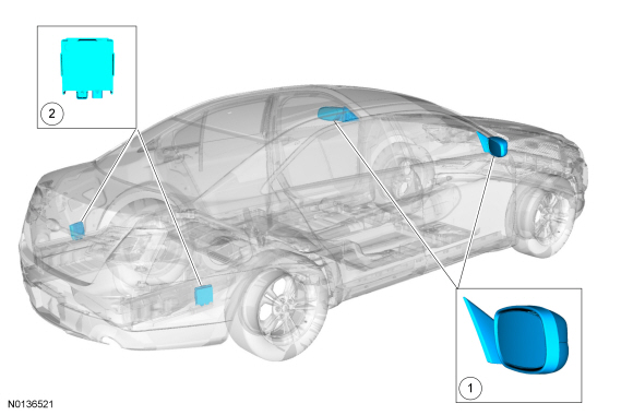
- Exterior rear view mirror
- SOD-R and SOD-L
Overview
BLIS is a vehicle feature that aids the driver in assessing whether another vehicle is within an area (blind zone) to either side of the vehicle extending rearward to approximately 3.05 m (10 ft) beyond the rear bumper while driving on roads and freeways. The system is not designed to prevent contact with other vehicles or objects. The CTA system assists the driver in backing out of a parking space.
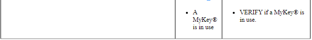
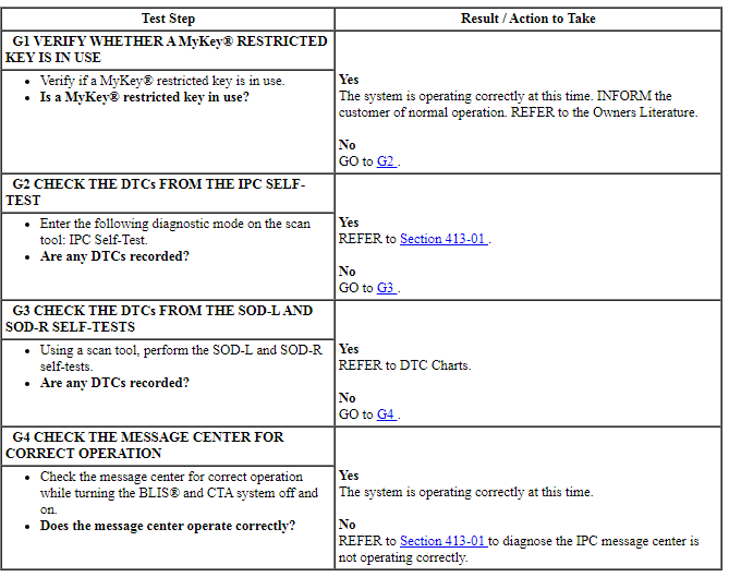
When a MyKey restricted key is in use, the BLIS and CTA system cannot be turned off in the IPC.
If the vehicle is towing a trailer, the BLIS or CTA system may detect the trailer and cause a false alert.
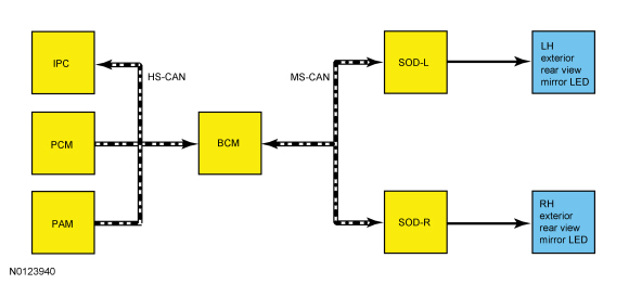
System Operation
System Diagram
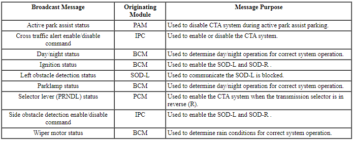
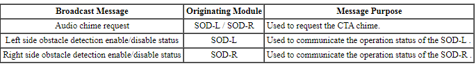
Network Message Chart
SOD-L Module Network Input Messages
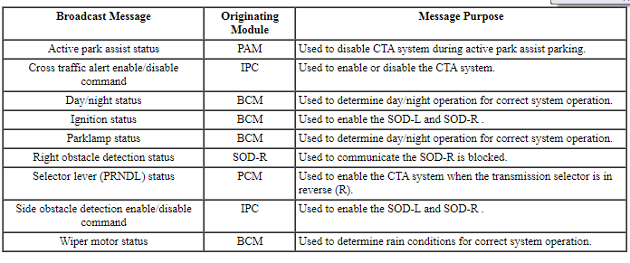
SOD-R Module Network Input Messages
IPC Module Network Input Messages
Blind Spot Information System (BLIS)
BLIS becomes active the first time the transmission is placed in DRIVE (D) after starting the engine and driving forward at a vehicle speed greater than 4.8 kmh (3 mph). Upon that initial sequence, BLIS remains active for all speeds including 0 kmh (0 mph). BLIS is also active if the transmission is placed in NEUTRAL (N). If the transmission is selected out of DRIVE (D) or NEUTRAL (N), the system has entered the CTA mode. When the transmission is shifted back into DRIVE (D), BLIS is activated once the vehicle is driven above 4.8 kmh (3 mph).
BLIS can trigger an alert for vehicles that enter the blind zone from the rear or merge into the blind zone from the side. The exterior mirror BLIS / CTA amber LED illuminates in the right and/or left exterior mirror. For vehicles that are being passed or enter the blind zone from the front, the system can trigger an alert only after the vehicle is present in the blind zone for more than 2 seconds. For vehicles that pass through the blind zone quickly, typically less than 2 seconds, BLIS cannot trigger an alert.
For correct operation of BLIS, the rear side bumper cover should be free of obstructions such as a large build up of mud, snow or ice. Small build up of debris and materials does not hinder the operation of the system. There should be no bumper stickers of any type placed in this area of the bumper cover.
NOTE: BLIS does not normally detect parked vehicles, pedestrians or objects such as fences, guard rails, trees, etc. BLIS does not provide any additional warning when the turn signal is activated.
Due to the nature of radar technology, false alerts and missed vehicles or objects (referred to as targets) may occur under certain circumstances. False alerts occur when the LED illuminates with no target present. False alerts up to 3% (3 out of 100 targets) is normal operation. Circumstances that cause false alerts are:
- freeway dividers
- concrete walls
- fencing
- sharp turns around a pole or building
- coming to a stop with a vehicle directly behind and very close
False alerts are temporary and self-correct.
Missed targets occur when a target is present and the LED does not illuminate. Missed targets up to 1% (1 out of 100 targets) are normal operation. Circumstances that cause missed targets are:
- debris build up on the rear bumper sides
- certain maneuvering of vehicles entering and exiting the blind zone
- vehicles passing through the blind zone at high rates of speed
- severe weather conditions
- when several vehicles forming a convoy pass through the blind zone
Cross-Traffic Alert System
The CTA system is an alert feature that assists the driver in backing out of a front-in parking space. The CTA system uses the SOD-L, SOD-R, exterior mirror BLIS / CTA LEDs, a warning chime from the IPC and a message in the IPC message center to notify the driver of impending traffic.
When the vehicle is in REVERSE (R), the CTA system can detect a vehicle that is approaching at a speed up to 24.1 kmh (15 mph) and is approximately 13.72 m (45 ft) from the side of the vehicle on the left or right side. The CTA system response time and performance can degrade if vehicles are approaching at speeds greater than 24.1 kmh (15 mph).
Backing out of parking spots slowly increases the radar sensor coverage in close proximity situations. The CTA system coverage decreases when parking at shallow angles, which is described in the Owner's Literature.
The CTA system utilizes the same SOD-L and SOD-R as the BLIS.
When the transmission is in REVERSE (R), the CTA system is active. The driver is warned of an approaching vehicle when an audio alert chime from the IPC sounds, the right or left exterior mirror BLIS / CTA amber LED flashes, and the message center displays CROSS TRAFFIC VEHICLE COMING FROM RIGHT or CROSS TRAFFIC VEHICLE COMING FROM LEFT to warn the driver from which direction the vehicle is approaching.
The CTA system cannot normally detect stationary vehicles, humans, animals or objects such as fences, guard rails or trees. The system does not function when the transmission is not in REVERSE (R).
The CTA system has some detection limitations due to the nature of the radar technology for the SOD-L and SOD-R. There can be certain instances where vehicles entering and exiting the CTA zone may not be detected. The circumstances that may cause non-detection are:
- Debris build up on the rear bumper sides
- The rear quarter panel of the vehicle is obstructed or partially obstructed by an adjacently parked vehicle or object
- Approaching vehicle passing at speeds greater than 24.1 kmh (15 mph)
- Severe weather conditions
- Driving in REVERSE (R) faster than 4.8 kmh (3 mph)
- Backing out of an angled parking spot
Due to the nature of radar technology, there may be certain instances when the CTA system alerts the operator, however no object or vehicle (referred to as targets) is present when backing up. This is known as a false alert. False alerts up to 5% (5 times out of 100 reversals) are normal. A false alert may occur when backing out of a garage or backing into a parking space and objects or vehicles are very close to the radar sensors. False alerts are temporary and self-correct.
Exterior Mirror Indication
The SOD-L and SOD-R run a self-diagnostic check on each vehicle start cycle and illuminate the exterior mirror BLIS / CTA amber LEDs for approximately 3 seconds indicating the BLIS and CTA is operational.
If a BLIS fault is present, the LEDs remain illuminated and a message in the message center displays BLIND SPOT SYSTEM FAULT. System faults can occur that cause the associated left or right exterior mirror BLIS / CTA amber LED not to illuminate; only the message center message fault is displayed.
BLIS and CTA Message Display
NOTE: The CTA system faults may not occur until the transmission is placed in REVERSE (R).
BLIS can be turned off by selecting the blind spot on/off function in the message center. The message BLIND SPOT OFF is displayed in the message center. When turning BLIS from on to off or off to on, the exterior mirror BLIS / CTA amber LEDs flash twice. When BLIS is off, the driver cannot receive any alerts. The system is reactivated on the next ignition cycle.
BLIS can be disabled permanently (even after an ignition cycle) by using a scan tool. When using the scan tool disable function in the programmable parameters menu, BLIS remains disabled until it is reactivated using the scan tool. When the system is disabled, the message center displays BLIND SPOT DISABLED. A system fault occurs if BLIS is not disabled in both the SOD-L and the SOD-R.
The CTA system can be turned off by selecting the CTA system on/off function in the message center. The message CROSS TRAFFIC OFF is displayed in the message center. The CTA system cannot be deactivated in the message center when the transmission is in REVERSE (R). The system is reactivated on the next ignition cycle.
The CTA system can be disabled permanently (even after an ignition cycle) by using a scan tool. When using the scan tool disable function in the programmable parameters menu, the CTA system remains disabled until it is reactivated using the scan tool. When the system is disabled, the message center displays CROSS TRAFFIC DISABLED. A system fault occurs if the CTA system is not disabled in both the SOD-L and the SOD-R.
There are some system faults that set DTCs which are logged in the SOD-L or SOD-R. These DTCs that are logged can set a message in the IPC message center that displays CROSS TRAFFIC SYSTEM FAULT or BLIND SPOT SYSTEM FAULT. There are also some symptom based faults that do not set a DTC.
Blocked Sensor
NOTE: A blockage will only be checked for if the wipers are on for more than 30 seconds.
Excessive build up of mud or snow on the inner and/or outer surfaces of the rear bumper, in front of the SOD-L or SOD-R can cause the BLIS or CTA system functionality to degrade. Heavy rain can have the same effect. If the system is in a blocked state, the radar misses targets, but still counts them. After approximately 4 counted/missed targets, the system sends a blocked sensor message over the MS-CAN to the IPC. The message center displays BLIND SPOT NOT AVAILABLE SENSOR BLOCKED or CROSS TRAFFIC NOT AVAILABLE SENSOR BLOCKED message. If the blocked condition is determined by either system the message center displays BLIND SPOT NOT AVAILABLE or CROSS TRAFFIC NOT AVAILABLE and the left and right exterior mirror BLIS / CTA LED illuminates.
The message center warning can be cleared by the driver but the exterior mirror BLIS / CTA LED remains illuminated. Once the blockage is removed, the system requires some drive time and a system detection of at least 2 vehicle objects prior to realizing it is unblocked. The ignition can also be cycled off to clear the blocked state. However, if the blockage is still present after the key cycle and after some drive time, the system detects again that it is blocked. The blocked message is displayed again in the message center.
Due to the nature of radar technology, it is possible to get a blocked sensor warning without the radar sensor being blocked. This is rare and is known as a false blockage warning. A false blocked condition either self-clears or clears after an ignition cycle.
Component Description
Side Obstacle Detection (SOD) Modules
The BLIS and the CTA system utilizes 2 modules that have integral radar sensors located rearward of the rear wheel under the rear bumper cover. The 2 modules, SOD-L and SOD-R, are hardwired to the exterior mirrors to illuminate the exterior rear view mirror LEDs.
DIAGNOSIS AND TESTING
Blind Spot Monitoring
DTC Charts
Diagnostics in this manual assume a certain skill level and knowledge of Ford-specific diagnostic practices. Refer to Diagnostic Methods in Section 100-00 for information about these practices.
NOTE: Refer to Description and Operation, IA with Push Button Start in Section 419-01C to review the procedures for achieving the various ignition states (ignition in accessory, ignition on, ignition start, ignition off) on vehicles with this feature.
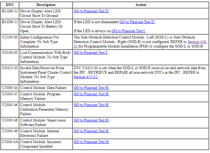
Side Obstacle Detection Control Module - Left (SOD-L) and Side Obstacle Detection Control Module - Right (SOD-R) DTC Chart
Symptom Chart
Diagnostics in this manual assume a certain skill level and knowledge of Ford-specific diagnostic practices. Refer to Diagnostic Methods in Section 100-00 for information about these practices.
NOTE: Refer to Description and Operation, Intelligent Access (IA) with Push Button Start in Section 419-01C to review the procedures for achieving the various ignition states (ignition in accessory, ignition on, ignition start, ignition off) on vehicles with this feature.
Pinpoint Tests
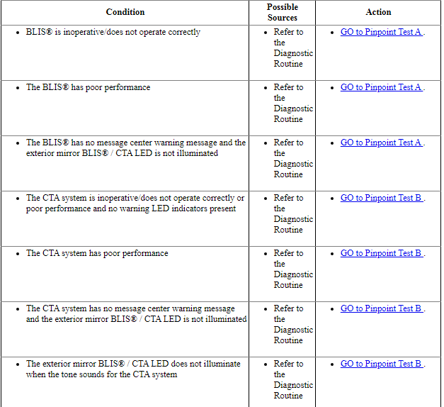
Pinpoint Test A: BLIS Is Inoperative Or Does Not Operate Correctly
Diagnostic Overview
Diagnostics in this manual assume a certain skill level and knowledge of Ford-specific diagnostic practices. Refer to Diagnostic Methods in Section 100-00 for information about these practices.
Normal Operation and Fault Conditions
REFER to Blind Spot Information System (BLIS) in Blind Spot Monitoring.
-
Possible Sources
- Wiring, terminals and connectors
- BLIS system is not configured on with the scan tool
- Vehicle speed signal
- BCM
- IPC
- PAM
- SOD-R
- SOD-L
Visual Inspection and Diagnostic Pre-checks
Check for debris buildup on the sides of the rear bumper cover.
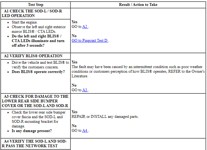
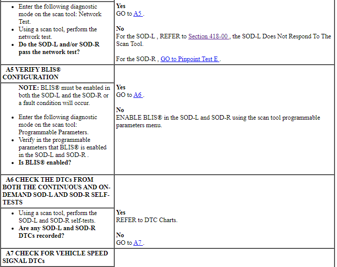
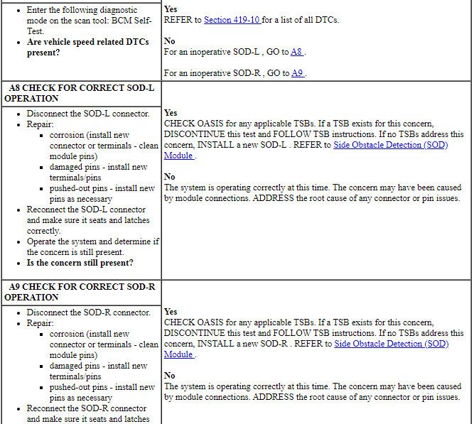
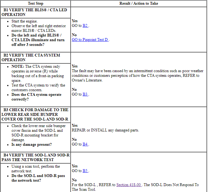
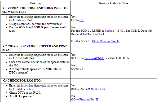
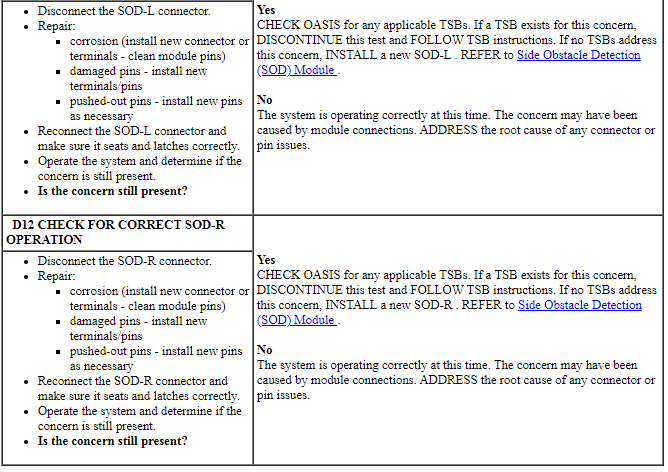
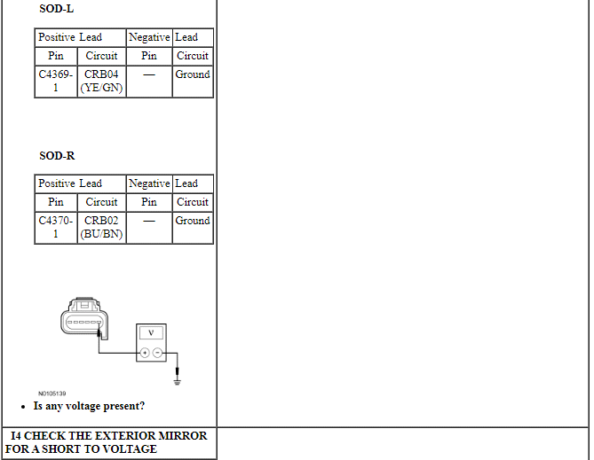
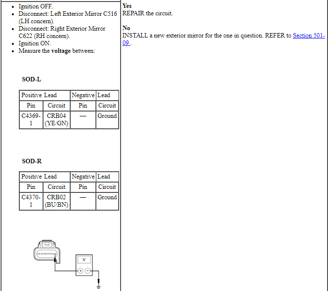
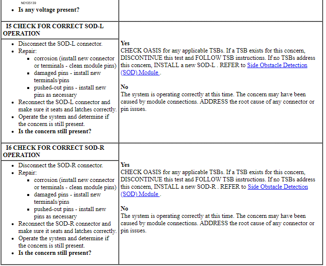
PINPOINT TEST A: BLIS IS INOPERATIVE OR DOES NOT OPERATE CORRECTLY
NOTICE: Use the correct probe adapter(s) when making measurements. Failure to use the correct probe adapter(s) may damage the connector.
Pinpoint Test B: The CTA System Is Inoperative Or Does Not Operate Correctly
Diagnostic Overview
Diagnostics in this manual assume a certain skill level and knowledge of Ford-specific diagnostic practices. Refer to Diagnostic Methods in Section 100-00 for information about these practices.
Normal Operation and Fault Conditions
REFER to Cross-Traffic Alert System in Blind Spot Monitoring.
REFER to Exterior Mirror Indication in Blind Spot Monitoring.
REFER to System Diagram in Blind Spot Monitoring.
REFER to Network Message Chart in Blind Spot Monitoring.
NOTE: The CTA system is turned off for one key cycle only when using the message center switches. Permanently disabling the CTA system is carried out in the Integrated Diagnostic System (IDS) programmable parameters menu.
The SOD-L and SOD-R are identical modules except that the SOD-R uses an address ground pin for configuration. The address ground is necessary so that the CTA system can decipher between the right and the left module.
-
Possible Sources
- Wiring, terminals and connectors
- CTA system is not configured on with the scan tool
- Vehicle speed signal
- IPC
- PAM
- SOD-R
- SOD-L
Visual Inspection and Diagnostic Pre-checks
Check for debris buildup on the sides of the rear bumper cover.
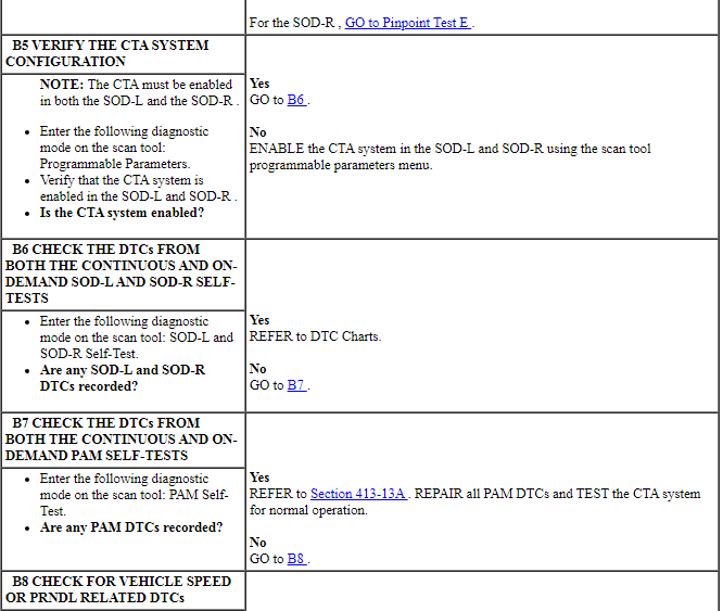
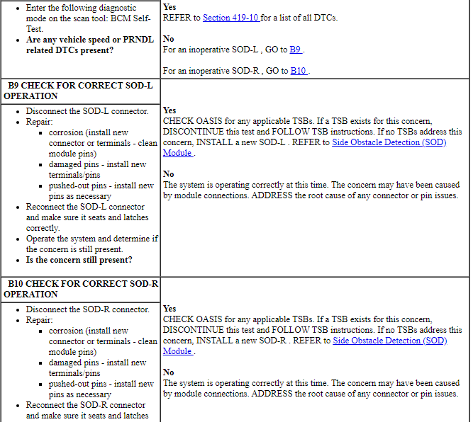
PINPOINT TEST B: THE CTA SYSTEM IS INOPERATIVE OR DOES NOT OPERATE CORRECTLY
NOTICE: Use the correct probe adapter(s) when making measurements. Failure to use the correct probe adapter(s) may damage the connector.
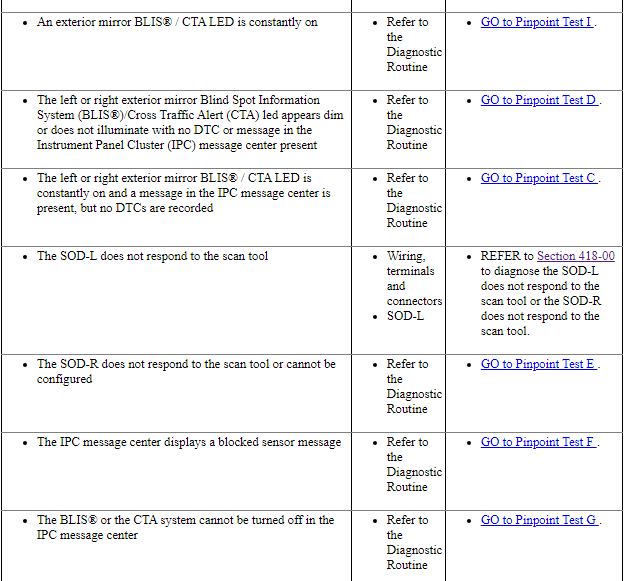
Pinpoint Test C: An Exterior Mirror LED Is Constantly On and An IPC Message Is Present
Diagnostic Overview
Diagnostics in this manual assume a certain skill level and knowledge of Ford-specific diagnostic practices. Refer to Diagnostic Methods in Section 100-00 for information about these practices.
Normal Operation and Fault Conditions
REFER to Exterior Mirror Indication in Blind Spot Monitoring.
REFER to System Diagram in Blind Spot Monitoring.
REFER to Network Message Chart in Blind Spot Monitoring.
-
Possible Sources
- Wiring, terminals and connectors
- SOD-R
- SOD-L
PINPOINT TEST C: AN EXTERIOR MIRROR LED IS CONSTANTLY ON AND AN IPC MESSAGE IS PRESENT
NOTICE: Use the correct probe adapter(s) when making measurements. Failure to use the correct probe adapter(s) may damage the connector.
Pinpoint Test D: DTC B11D6:11 Or DTC B11D6:15
Diagnostic Overview
Diagnostics in this manual assume a certain skill level and knowledge of Ford-specific diagnostic practices. Refer to Diagnostic Methods in Section 100-00 for information about these practices.
Refer to Wiring Diagrams Cell 136, Vehicle Emergency Messaging System for schematic and connector information.
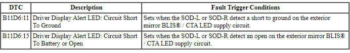
DTC Fault Trigger Conditions
-
Possible Sources
- Wiring, terminals and connectors
- Exterior mirror BLIS / CTA LED
- SOD-R
- SOD-L
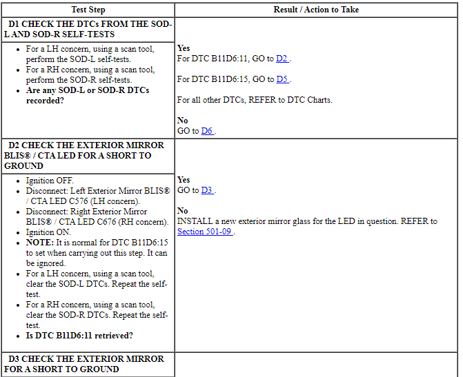
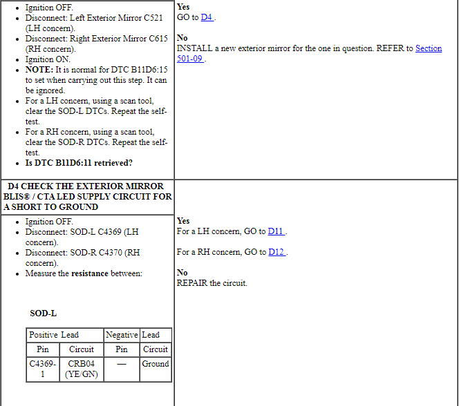
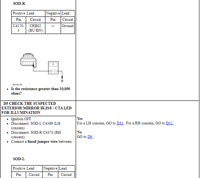
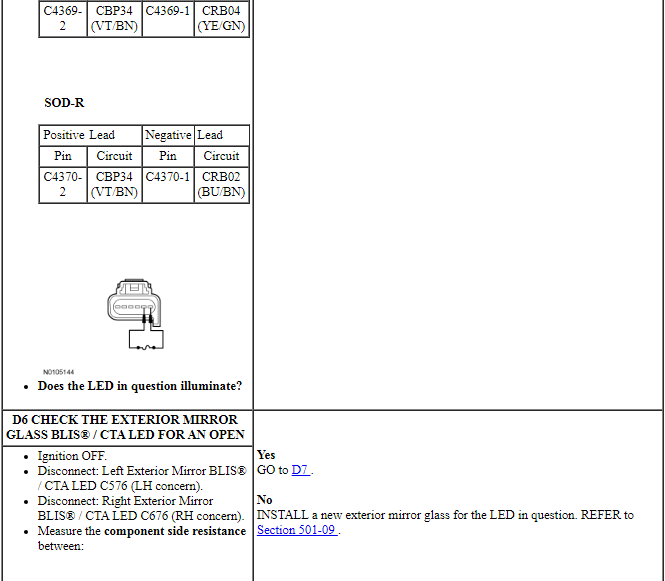
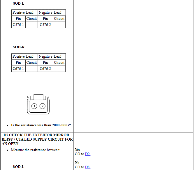
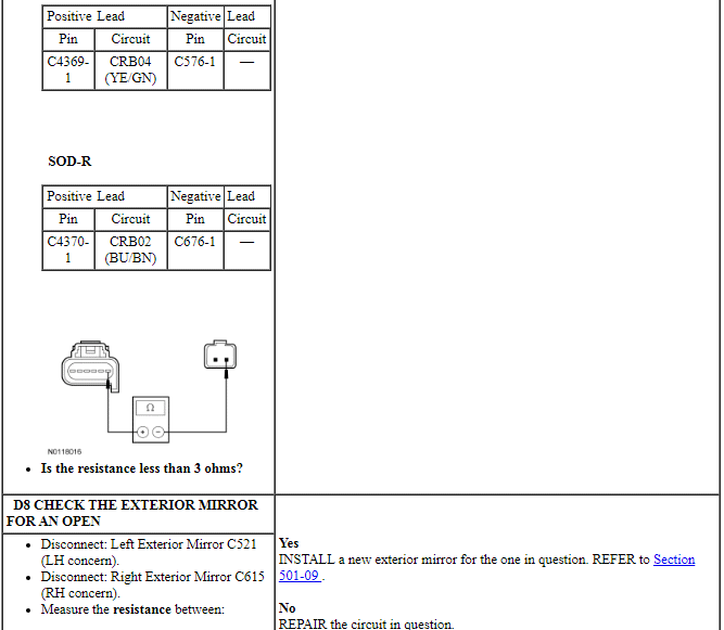
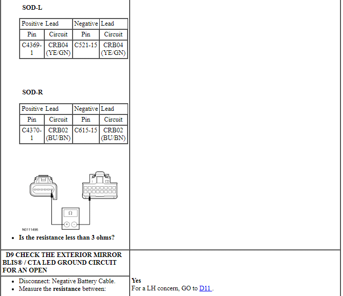
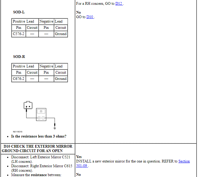
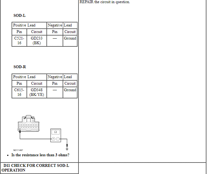
PINPOINT TEST D: DTC B11D6:11 OR DTC B11D6:15
NOTICE: Use the correct probe adapter(s) when making measurements. Failure to use the correct probe adapter(s) may damage the connector.
NOTE: Failure to disconnect the battery when instructed will result in false resistance readings. Refer to Section 414-01.
Pinpoint Test E: The SOD-R Does Not Respond To The Scan Tool Or Cannot Be Configured
Diagnostic Overview
Diagnostics in this manual assume a certain skill level and knowledge of Ford-specific diagnostic practices. Refer to Diagnostic Methods in Section 100-00 for information about these practices.
Refer to Wiring Diagrams Cell 136, Vehicle Emergency Messaging System for schematic and connector information.
Normal Operation and Fault Conditions
The SOD-R uses an address ground pin for configuration. The address ground is necessary so the BLIS or the CTA system can decipher between the SOD-R and the SOD-L during configuration. The SOD-R communicates over the MS-CAN.
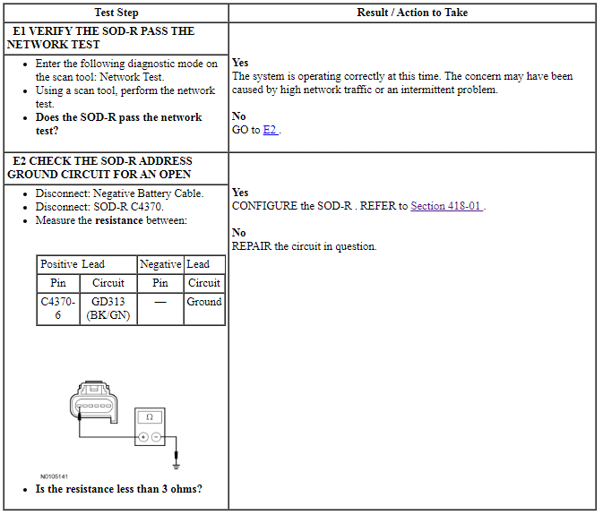
PINPOINT TEST E: THE SOD-R DOES NOT RESPOND TO THE SCAN TOOL OR CANNOT BE CONFIGURED
NOTICE: Use the correct probe adapter(s) when making measurements. Failure to use the correct probe adapter(s) may damage the connector.
NOTE: Failure to disconnect the battery when instructed will result in false resistance readings. Refer to Section 414-01.
Pinpoint Test F: The Instrument Panel Cluster (IPC) Message Center Displays A Blocked Sensor Message
Diagnostic Overview
Diagnostics in this manual assume a certain skill level and knowledge of Ford-specific diagnostic practices. Refer to Diagnostic Methods in Section 100-00 for information about these practices.
Refer to Wiring Diagrams Cell 136 for schematic and connector information.
Normal Operation and Fault Conditions
A blocked sensor message indicates that there is an obstruction on the rear bumper cover fascia that does not allow the radar from the SOD-R and SOD-L to penetrate.
REFER to BLIS and CTA Message Display in Blind Spot Monitoring.
-
Possible Sources
- SOD-R
- SOD-L
Visual Inspection and Diagnostic Pre-checks
Check for debris buildup on the sides of the rear bumper cover.
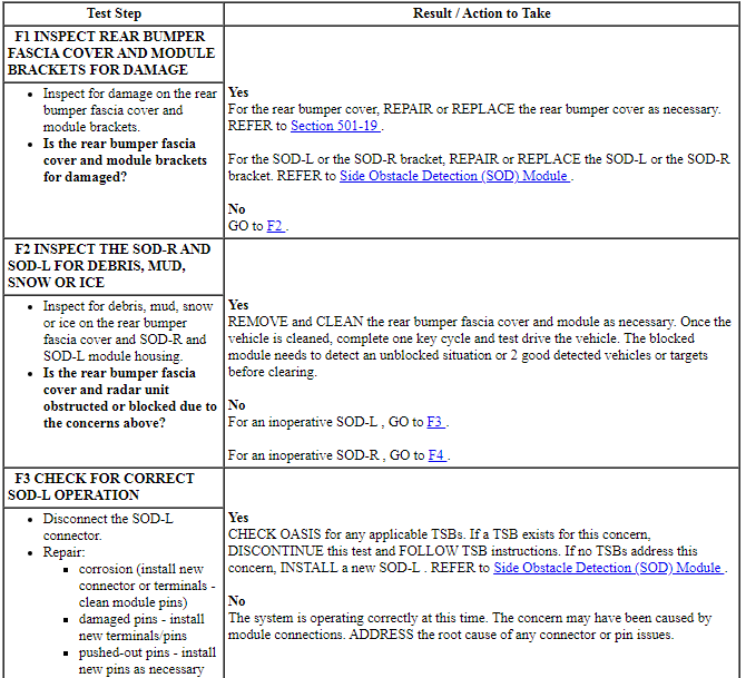
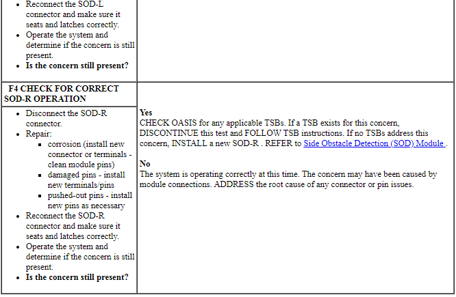
PINPOINT TEST F: THE IPC MESSAGE CENTER DISPLAYS A BLOCKED SENSOR MESSAGE
NOTICE: Use the correct probe adapter(s) when making measurements. Failure to use the correct probe adapter(s) may damage the connector.
Pinpoint Test G: The Blind Spot Information System (BLIS) and Cross Traffic Alert (CTA) System Cannot Be Turned Off In The Instrument Panel Cluster (IPC) Message Center
Diagnostic Overview
Diagnostics in this manual assume a certain skill level and knowledge of Ford-specific diagnostic practices. Refer to Diagnostic Methods in Section 100-00 for information about these practices.
Refer to Wiring Diagrams Cell 136 for schematic and connector information.
Normal Operation and Fault Conditions
The BLIS and/or CTA system are turned off for one key cycle only when using the message center switches. Permanently disabling the BLIS and/or CTA system is carried out in the Integrated Diagnostic System (IDS) programmable parameters menu.
REFER to BLIS and CTA Message Display in Blind Spot Monitoring.
-
Possible Sources
- Wiring, terminals and connectors
- IPC
PINPOINT TEST G: THE BLIS AND CTA SYSTEM CANNOT BE TURNED OFF IN THE IPC MESSAGE CENTER
Pinpoint Test H: DTC U3000:44, 45, 46, 48, 49 Or 4A
Diagnostic Overview
Diagnostics in this manual assume a certain skill level and knowledge of Ford-specific diagnostic practices. Refer to Diagnostic Methods in Section 100-00 for information about these practices.
Refer to Wiring Diagrams Cell 136 for schematic and connector information.
Normal Operation and Fault Conditions
On each ignition cycle, the SOD-L and SOD-R run a self-diagnostic check during which the exterior mirror BLIS / CTA LEDs illuminate for 3 seconds then turn off indicating the system is operational. If a DTC fault is present, a system fault message is observed in the message center.
DTC Fault Trigger Conditions
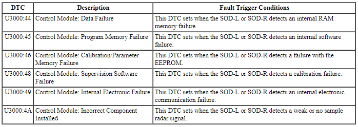
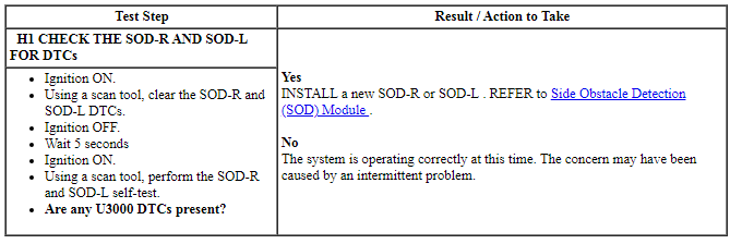
PINPOINT TEST H: DTC U3000:44, 45, 46, 48, 49 OR 4A
Pinpoint Test I: An Exterior Mirror BLIS / CTA LED Is Constantly On
Refer to Wiring Diagrams Cell 136, Vehicle Emergency Messaging System for schematic and connector information.
Normal Operation and Fault Conditions
REFER to Exterior Mirror Indication in Blind Spot Monitoring.
DTC Fault Trigger Conditions

-
Possible Sources
- Wiring, terminals and connectors
- Exterior mirror BLIS / CTA LED
- SOD-R
- SOD-L
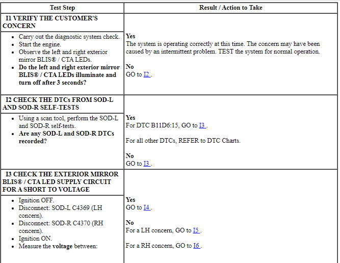
PINPOINT TEST I: AN EXTERIOR MIRROR BLIS / CTA LED IS CONSTANTLY ON
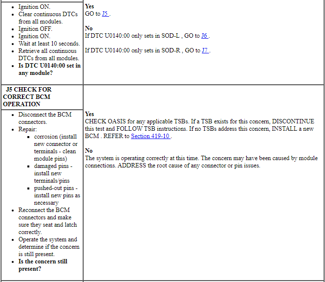
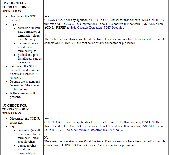
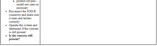
Pinpoint Test J: DTC U0140:00
Diagnostic Overview
Diagnostics in this manual assume a certain skill level and knowledge of Ford-specific diagnostic practices. Refer to Diagnostic Methods in Section 100-00 for information about these practices.
Normal Operation and Fault Conditions
REFER to Network Message Chart in Blind Spot Monitoring.
DTC Fault Trigger Conditions

-
Possible Sources
- BCM
- SOD-R
- SOD-L
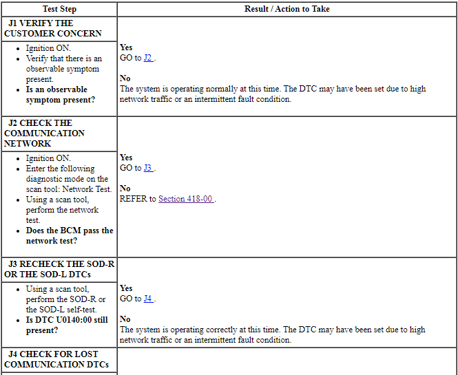
PINPOINT TEST J: DTC U0140:00
REMOVAL AND INSTALLATION
Side Obstacle Detection (SOD) Module
NOTE: Rear bumper cover removed for clarity.
NOTE: Left rear quarter panel shown, right side similar.
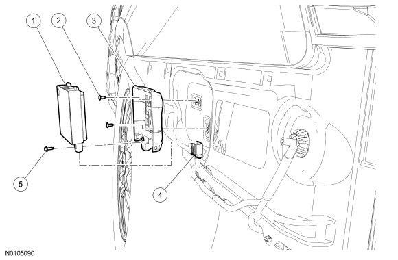
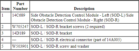
Removal and Installation
- NOTE: Module configuration is required when a new Side Obstacle Detection Control Module - Left (SOD-L) or Side Obstacle Detection Control Module - Right (SOD-R) is being installed. Upload the SOD-L or SOD-R module configuration information to the scan tool. For additional information, refer to Programmable Module Installation (PMI) in Section 418-01.
- With the vehicle in NEUTRAL, position it on a hoist. For additional information, refer to Section 100-02.
- Remove 4 fender spash shield screws and gently flex the shield to access
the SOD-L or SOD-R.
- Remove the screw and washer.
- Disconnect the electrical connector.
- Remove the SOD-L or the SOD-R.
- If removing the bracket, remove the 2 screws and bracket.
- To install, reverse the removal procedure.
- Download the SOD-L or the SOD-R configuration information. For additional information, refer to Section 418-01.
- After the configuration of the LH and RH modules is complete, turn the ignition to off then start the engine. With foot on the brake paedal shift the PRNDL through R, N, D and then back to Park. Check the cluster message center that there are no BLIS or CTA error messages. Shifting through the PRNDL gears is necessary because some BLIS and CTA faults are not reported to the cluster until the PRNDL enters R or D gears.
 Collision Avoidance
DESCRIPTION AND OPERATION
Forward Collision Warning
Overview
The forward collision warning system alerts the driver of a collision risk
with a red warning LED indicator bar located above the instrume ...
 Lane Departure Warning
DESCRIPTION AND OPERATION
Lane Departure Warning
Overview
The LDW is composed of the lane keeping alert and lane keeping aid functions.
The lane keeping alert detects unintentional drifting ...
Other materials:
Cleaning products
For best results, use the following products or products of equivalent
quality:
Motorcraft Bug and Tar Remover (ZC-42)
Motorcraft Custom Bright Metal Cleaner (ZC-15)
Motorcraft Detail Wash (ZC-3-A)
Motorcraft Dusting Cloth (ZC-24)
Motorcraft Engine Shampoo and Degreaser (United States only) (Z ...
Cleaning the exterior
Wash your vehicle regularly with cool or lukewarm water and a neutral
pH shampoo, such as Motorcraft® Detail Wash.
• Never use strong household detergents or soap, such as dish washing
or laundry liquid. These products can discolor and spot painted
surfaces.
• Never wash a vehicle that ...
Waxing
Regular waxing is necessary to protect the paint on your car from the
elements. We recommend that you wash and wax the painted surface
once or twice a year.
When washing and waxing, park your vehicle in a shaded area out of
direct sunlight. Always wash your vehicle before applying wax.
• ...
