DESCRIPTION AND OPERATION
Forward Collision Warning
Overview
The forward collision warning system alerts the driver of a collision risk with a red warning LED indicator bar located above the instrument panel (part of the HUD module) and an audible warning chime from the IPC. The ABS module uses 3 braking strategies based on inputs from the C-CM.
System Operation
System Diagram
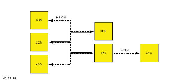
Network Message Chart
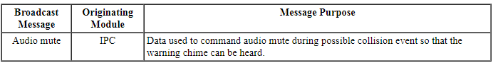
Module Network Input Messages - ACM
Module Network Input Messages - C-CM

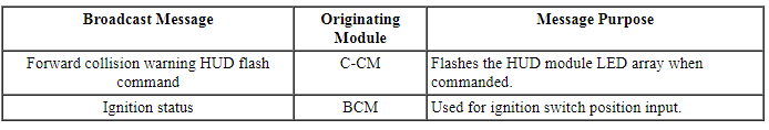
Module Network Input Messages - HUD
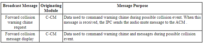
Module Network Input Messages - IPC
Module Network Input Messages - ABS Module
Collision Warning With Brake Support
The forward collision warning system works in conjunction with the adaptive cruise control system. During a possible collision event, the C-CM commands:
- the HUD module to flash red warning LEDs.
- the IPC to activate a chime and messages.
- the ACM to mute audio volume.
- the ABS module to apply one of 3 braking strategies.
The forward collision warning system is activated when the vehicle is moving forward at a speed greater than 8 kmh (5 mph). The C-CM determines the distance and relative speed of the vehicle that is in the path of travel, utilizing a radar sensor (integral to the C-CM ) to detect other vehicles that are moving in the same direction. If the C-CM determines that a collision is possible, the C-CM commands the HUD module LEDs to flash, the ABS module to one of the three braking strategies, and the IPC to chime.
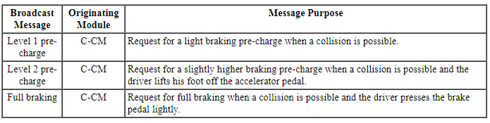
There are 3 braking strategies that are part of the Collision Warning system:
- Pre-charge level 1 - a light brake pre-charge when a collision is possible.
- Pre-charge level 2 - a slightly higher brake pre-charge when a collision is possible and the driver lifts his foot off of the accelerator pedal.
- Full braking - is applied when a collision is possible and the driver presses the brake pedal lightly.
The forward collision warning system and audible warning chime can be enabled and disabled through the message center display in the IPC. The system reverts to ON each ignition cycle. The HUD module and/or chime activates briefly to confirm the last setting. For vehicles with a base IPC, the sensitivity of detection is changed in the message center from a high sensitivity ( <----->) to a low sensitivity ( <->).
For vehicles with an optional IPC, there are 3 levels of sensitivity detection (LONG, NORMAL and SHORT) that are changed in the message center display.
If a MyKey restricted key is in use, the MyKey turns on the forward collision warning and will not allow the MyKey user to disable the audio or visual forward collision warning system. However, the MyKey user is able to adjust the forward collision warning sensitivity.
When a system fault is detected with the forward collision warning system, the message COLLISION WARN NOT AVAILABLE, COLLISION WARN NOT AVAILABLE SENSOR BLOCKED, or COLLISION WARNING MALFUNCTION is displayed in the IPC message center.
Component Description
Cruise Control Module (C-CM)
The C-CM contains a radar sensor unit that determines the distance and relative speed of the vehicle that is in the path of travel.
Head Up Display (HUD) Module
The HUD module contains the red LEDs that warn the driver of a possible collision event when commanded by the C-CM. There are certain situations when the warning LEDs cannot be seen, such as strong sunlight or when wearing sunglasses. The HUD module has a temperature sensor circuit that is integral to the module that senses the temperature of the LEDs internal to the module. When a high passenger compartment temperature such as strong sunlight is sensed by the temperature sensor, the warning LEDs can be temporarily disengaged. If this occurs, only the audible warning chime is used. Warnings may not appear if the distance to the vehicle ahead is very small or if the steering wheel and pedal movements are large, for example, due to a very active driving style.
DIAGNOSIS AND TESTING
Forward Collision Warning
DTC Charts
Diagnostics in this manual assume a certain skill level and knowledge of Ford-specific diagnostic practices. Refer to Diagnostic Methods in Section 100-00 for information about these practices.
NOTE: Refer to Description and Operation, Intelligent Access (IA) with Push Button Start in Section 419-01C to review the procedures for achieving the various ignition states (ignition in accessory, ignition on, ignition start, ignition off) on vehicles with this feature.
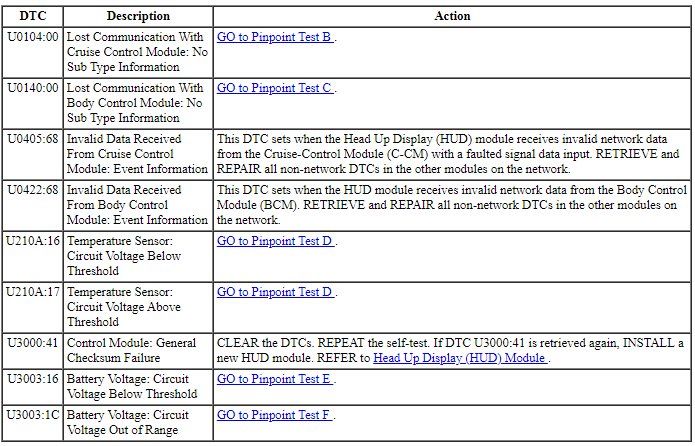
Head Up Display (HUD) Module DTC Chart
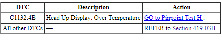
Cruise-Control Module (C-CM) DTC Chart
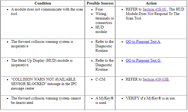
Symptom Chart
Diagnostics in this manual assume a certain skill level and knowledge of Ford-specific diagnostic practices. Refer to Diagnostic Methods in Section 100-00 for information about these practices.
Pinpoint Tests
Pinpoint Test A: The Forward Collision Warning System Is Inoperative
Diagnostic Overview
Diagnostics in this manual assume a certain skill level and knowledge of Ford-specific diagnostic practices. Refer to Diagnostic Methods in Section 100-00 for information about these practices.
Refer to Wiring Diagrams Cell 136, Vehicle Emergency Messaging System for schematic and connector information.
Normal Operation and Fault Conditions
REFER to Collision Avoidance Operation in Forward Collision Warning.
-
Possible Sources
- Fuse
- Wiring, terminals or connectors
- C-CM
- HUD module
- IPC
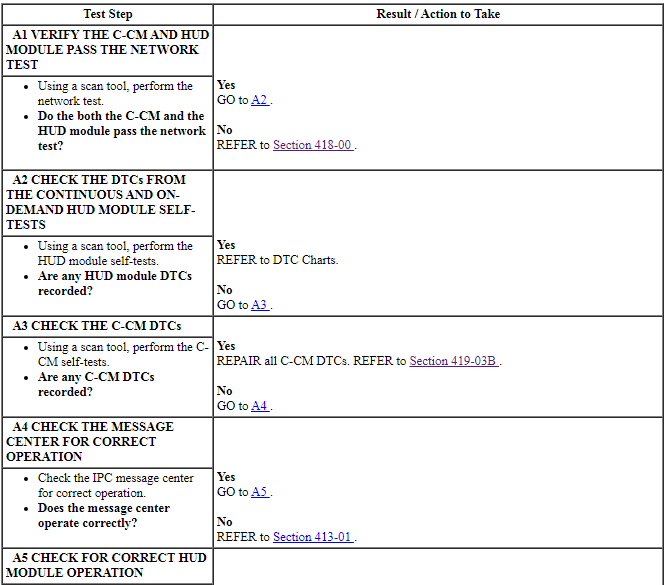
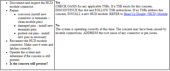
PINPOINT TEST A: THE FORWARD COLLISION WARNING SYSTEM IS INOPERATIVE
NOTICE: Use the correct probe adapter(s) when making measurements. Failure to use the correct probe adapter(s) may damage the connector.
Pinpoint Test B: DTC U0104:00
Diagnostic Overview
Diagnostics in this manual assume a certain skill level and knowledge of Ford-specific diagnostic practices. Refer to Diagnostic Methods in Section 100-00 for information about these practices.
DTC Fault Trigger Conditions

-
Possible Sources
- C-CM
- HUD module
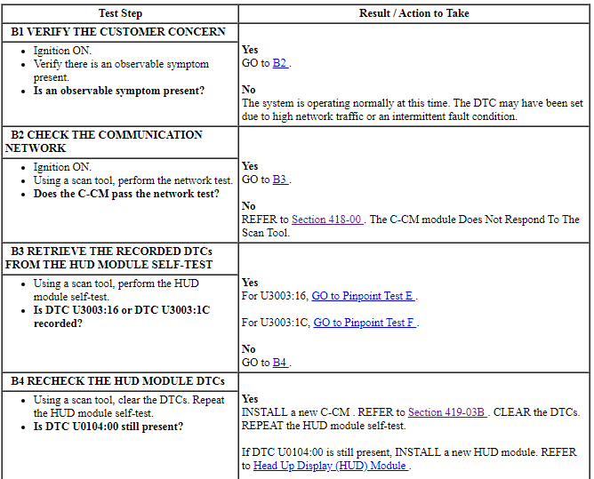
PINPOINT TEST B: DTC U0104:00

Pinpoint Test C: DTC U0140:00
Diagnostic Overview
Diagnostics in this manual assume a certain skill level and knowledge of Ford-specific diagnostic practices. Refer to Diagnostic Methods in Section 100-00 for information about these practices.
DTC Fault Trigger Conditions
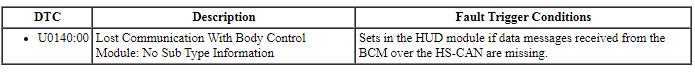
-
Possible Sources
- BCM
- HUD module
PINPOINT TEST C: DTC U0140:00
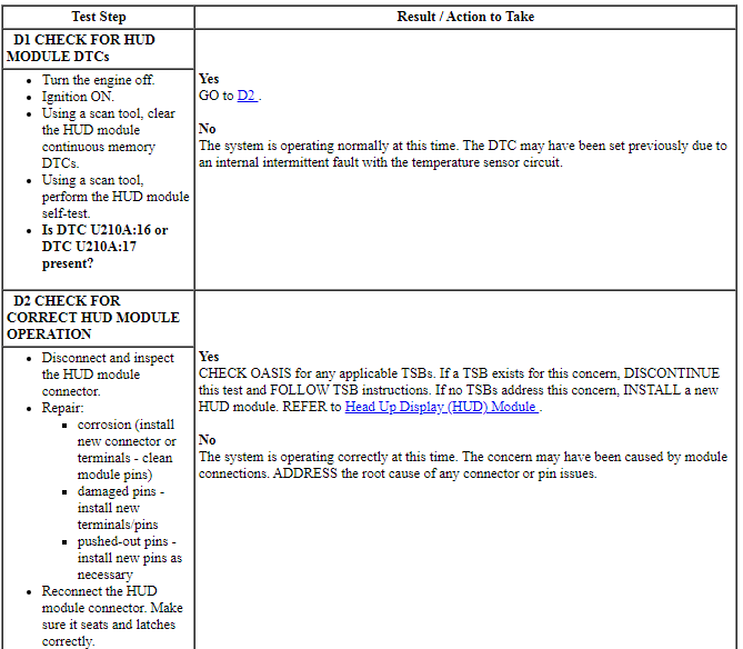
Pinpoint Test D: DTC U210A:16 Or DTC U210A:17
Diagnostic Overview
Diagnostics in this manual assume a certain skill level and knowledge of Ford-specific diagnostic practices. Refer to Diagnostic Methods in Section 100-00 for information about these practices.
DTC Fault Trigger Conditions
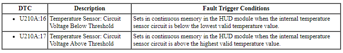
-
Possible Sources
- HUD module
PINPOINT TEST D: DTC U210A:16 OR DTC U210A:17
Pinpoint Test E: DTC U3003:16
Diagnostic Overview
Diagnostics in this manual assume a certain skill level and knowledge of Ford-specific diagnostic practices. Refer to Diagnostic Methods in Section 100-00 for information about these practices.
Refer to Wiring Diagrams Cell 136, Vehicle Emergency Messaging System for schematic and connector information.
DTC Fault Trigger Conditions

-
Possible Sources
- Wiring, terminals or connectors
- Battery
- Generator
- PCM
- RFA module
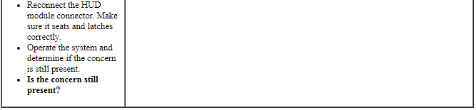
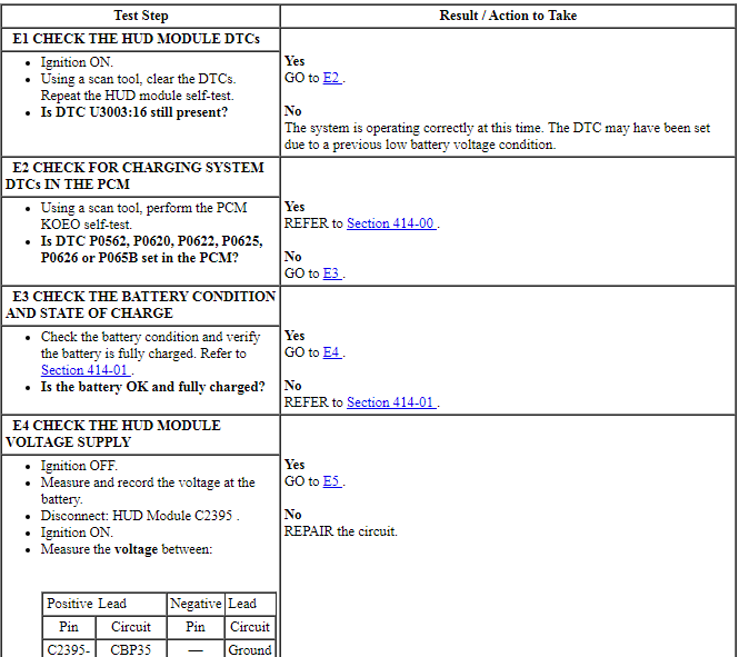
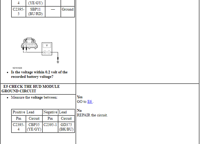
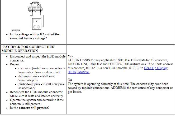
PINPOINT TEST E: DTC U3003:16
NOTICE: Use the correct probe adapter(s) when making measurements. Failure to use the correct probe adapter(s) may damage the connector.
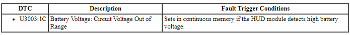
Pinpoint Test F: DTC U3003:1C
Diagnostic Overview
Diagnostics in this manual assume a certain skill level and knowledge of Ford-specific diagnostic practices. Refer to Diagnostic Methods in Section 100-00 for information about these practices.
DTC Fault Trigger Conditions
-
Possible Sources
- Wiring, terminals or connectors
- Battery
- Generator
- HUD module
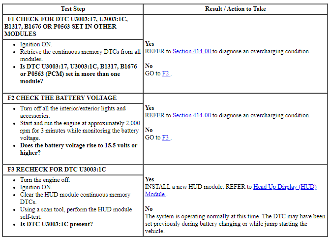
PINPOINT TEST F: DTC U3003:1C
NOTE: DTC U3003:1C may be stored in the module memory due to past battery charging or vehicle jump starting events.
Pinpoint Test G: The Head Up Display (HUD) Module Is Inoperative
Diagnostic Overview
Diagnostics in this manual assume a certain skill level and knowledge of Ford-specific diagnostic practices. Refer to Diagnostic Methods in Section 100-00 for information about these practices.
Normal Operation and Fault Conditions
REFER to Head Up Display (HUD) Module in Forward Collision Warning.
-
Possible Sources
- C-CM
- HUD module
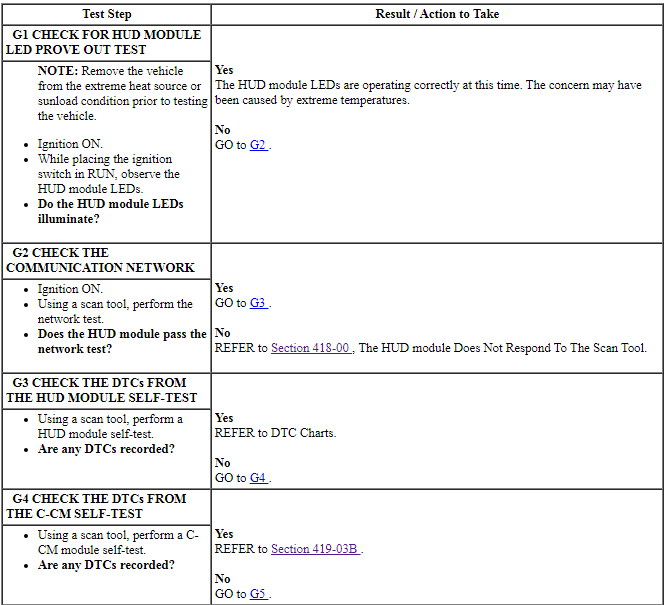
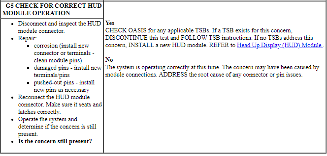
PINPOINT TEST G: THE HUD MODULE IS INOPERATIVE
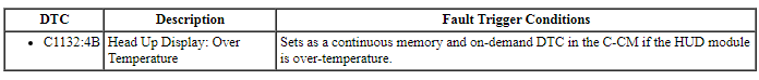
Pinpoint Test H: DTC C1132:4B
Diagnostic Overview
Diagnostics in this manual assume a certain skill level and knowledge of Ford-specific diagnostic practices. Refer to Diagnostic Methods in Section 100-00 for information about these practices.
Normal Operation and Fault Conditions
The Head Up Display (HUD) module is designed with a temperature sensor internal to the module. Due to extremely hot weather conditions, the temperature sensor circuit allows the HUD module to disable under high temperature conditions, which could damage the HUD module LEDs. The HUD module is designed with a LED prove-out test. Upon each ignition cycle when the ignition switch is in RUN, the LEDs illuminate for a period of time indicating the HUD module is functional.
DTC Fault Trigger Conditions
-
Possible Sources
- HUD module
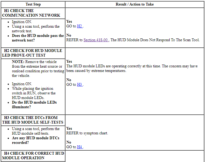
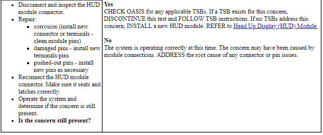
PINPOINT TEST H: DTC C1132:4B
REMOVAL AND INSTALLATION
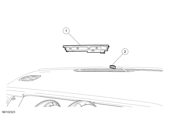
Head Up Display (HUD) Module
.png)
Removal and Installation
- Gently pry with a suitable tool (such as a small flat-blade screwdriver)
on the LH side of the Head Up Display (HUD) module to release it from the
instrument panel upper section.
- Disconnect the electrical connector.
- To install, reverse the removal procedure.
 Cruise Control - Adaptive
SPECIFICATIONS
Torque Specifications
DESCRIPTION AND OPERATION
Cruise Control
Component Location
C-CM
HUD module
Overview
The adaptive cruise control system is controlled by the steeri ...
 Side And Rear Vision
DESCRIPTION AND OPERATION
Blind Spot Monitoring
Component Location
Exterior rear view mirror
SOD-R and SOD-L
Overview
BLIS is a vehicle feature that aids the driver in assessing whe ...
Other materials:
Disassembly
Engine
Special Tool(s)
Material
WARNING: Do not smoke, carry lighted tobacco or have an open flame of any
type when working on or near any fuel-related component. Highly flammable
mixtures are always present and may be ignited. Failure to follow these
instructions may result in serious person ...
General Procedures
Accessing Mounting Bolts On an Inoperative Power Seat
General Equipment
Drill(s)
WARNING: Wear protective gloves when handling components or parts that
have pointed or sharp edges. Failure to follow this instruction may result in
serious personal injury.
NOTE: Typical driver seat shown, ot ...
Diagnosis and Testing
Automatic Transmission
Special Tool(s)
Material
DTC Chart
Diagnostics in this manual assume a certain skill level and knowledge of
Ford-specific diagnostic practices. Refer to Diagnostic Methods in Section
100-00 for information about these practices.
For all other DTCs, refe ...
