SPECIFICATIONS
Torque Specifications

DESCRIPTION AND OPERATION
Cruise Control
Component Location
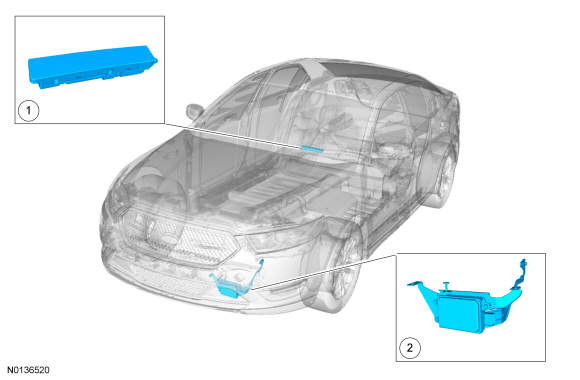
- C-CM
- HUD module
Overview
The adaptive cruise control system is controlled by the steering wheel mounted switches (ON/OFF, SET, CNCL, RES and GAP) that are integrated into the LH steering wheel switch.
The cruise control system maintains a selected vehicle speed between 29 kmh (18 mph) and the maximum limited vehicle speed and displays that speed in the IPC message center. When a MyKey restricted key is in use and maximum speed limiter is turned on, vehicle speed is limited. The maximum vehicle speed can be set to 105 kmh (65 mph), 113 kmh (70 mph), 121 kmh (75 mph), or 129 kmh (80 mph).
The vehicle maintains the selected speed until another slower vehicle is detected ahead in the same lane by the radar sensor unit inside the C-CM. The vehicle speed is adjusted automatically to maintain a preset distance gap. The vehicle maintains the distance gap and the brakes automatically apply to slow the vehicle to maintain the gap to the vehicle ahead.
The cruise control system is controlled by the PCM.
System Operation
System Diagram
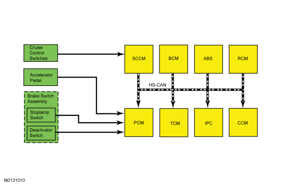
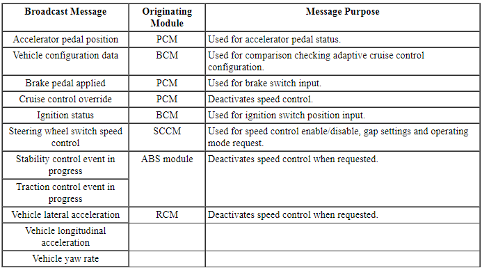
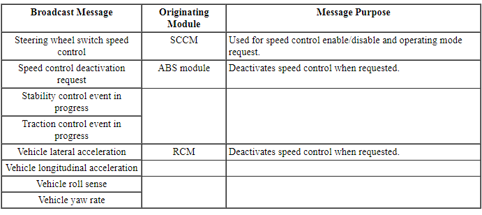
Network Message Chart
Module Network Input Messages - ABS Module

Module Network Input Messages - C-CM
Module Network Input Messages - IPC

Module Network Input Messages - PCM
Adaptive Cruise Control (ACC) Operation
NOTE: For a complete illustration of the adaptive cruise control indicators and graphic displays, refer to the Owner's Literature.
The adaptive cruise control system functions much like the standard cruise control system. The adaptive cruise control system automatically adjusts the vehicle speed to maintain a set gap distance from the front of the vehicle and the vehicle in the same path of travel. When the adaptive cruise control system is on and is following a vehicle ahead or a vehicle enters the same driving lane, a follow vehicle graphic is displayed in the message center.
The adaptive cruise control system does not function if the vehicle speed is below 29 kmh (18 mph). As the vehicle slows down during automatic braking, the adaptive cruise control system discontinues braking at 29 kmh (18 mph). At that speed, an audible alarm sounds and the automatic braking from the ABS module is released. The driver must take over the vehicle braking control.
The cruise control deactivator switch (which is integral to the stoplamp switch) is an additional safety feature. When the brake pedal is pressed, an electrical signal is sent from the stoplamp switch to the PCM deactivating the cruise control system. Under increased brake pedal effort, the cruise control deactivator switch opens and removes the ground signal from the PCM input circuit, releasing the throttle immediately deactivating the system.
The ABS module monitors the yaw rate signal from the RCM and compares it to the wheel speed and steering wheel angle signals. If the ABS module determines the yaw rate is invalid, the ABS module disables the adaptive cruise control. The message center displays the message COLLISION WARNING MALFUNCTION and/or ADAPTIVE CRUISE MALFUNCTION.
The ABS module estimates brake temperature by monitoring applied brake pressure over a period of time and sends a message to the C-CM when the estimated temperature is above a given threshold. An alarm sounds and the adaptive cruise control system is deactivated until the estimated brake temperature within the ABS module returns to cooler operating conditions. This condition can happen in a hilly or mountainous driving terrain.
Cruise Control Indicator
The adaptive cruise control indicator, located in the IPC illuminates gray and the previous gap setting and SET graphic is displayed indicating the system is in standby mode. This notifies the driver that the system is ready and the vehicle can be accelerated to the desired speed.
Steering Wheel Switch Function
The adaptive cruise control steering wheel mounted switches are momentary contact switches that toggle up and down for the cruise control switch state. Pressing and releasing the steering wheel cruise control ON/OFF switch turns the cruise control system on. Pressing up (SET+) and releasing the SET switch sets the vehicle speed and stores the set speed in memory. The adaptive cruise control indicator illuminates green and the message center displays the set speed and gap setting graphic.
There are 2 ways to change the set speed. The first way is to accelerate or brake to the desired speed and press and release the SET cruise control switch until the desired set speed is shown on the message center. The second way is by tapping the SET+ or the SET- switch while in the set mode, increasing or decreasing the displayed set speed by 1.6 kmh (1 mph) per tap. If the respective button is pressed and held, the displayed set speed continues to increase or decrease until the button is released. The adaptive cruise control system may apply the brakes to slow the vehicle down to the new set speed. The set speed displays continuously in the message center while the adaptive cruise control system is active.
Pressing and releasing the OFF switch, or switching the ignition to OFF, turns the adaptive cruise control system off. The adaptive cruise control set speed memory is erased.
Pressing the brake pedal or pressing the RES/CNCL switch puts the adaptive cruise control system in standby mode and the last set speed is displayed in the message center with a strike through. Pressing the RES/CNCL button when the adaptive cruise control system is in standby mode causes the vehicle to accelerate to the last set speed. The set speed continuously displays in the message center while the adaptive cruise control system is active. The RES/CNCL button does not function if the OFF button is pressed, the ignition is cycled OFF, or if the current vehicle speed is below the minimum operational speed.
The adaptive cruise control system has the capability for the driver to change from adaptive cruise control to standard cruise control. The LH 5-way steering wheel switch is used to switch from the adaptive cruise control system to standard cruise control system within the message center. For information on selecting the standard cruise control in the message center, refer to the Owner's Literature. Once the driver has selected the standard cruise control in the message center, the adaptive cruise control indicator is replaced by the standard cruise control indicator. The vehicle no longer responds to lead vehicles or automatic braking. Upon the next vehicle ignition cycle, the vehicle defaults back to the adaptive cruise control system.
Gap Setting
When a vehicle ahead enters the same lane or a slower vehicle is ahead in the same lane, the vehicle speed adjusts automatically to maintain a preset distance gap. A bar graph graphic with 4 preset distance gap settings are displayed in the message center. Pressing up (decrease) or down (increase) on the steering wheel cruise control gap switch increases or decreases the distance from the vehicle ahead. If all of the bars are illuminated, this is the longest gap setting. If only one bar is illuminated that is the shortest gap setting.
The vehicle maintains the distance gap to the vehicle ahead until:
- the vehicle ahead accelerates to a speed above the set speed,
- the vehicle ahead moves out of the lane or out of view,
- the vehicle speed falls below 29 kmh (18 mph),
- or a new gap distance is set.
After each ignition cycle, the previous gap setting is remembered and the system is set to that gap setting.
The distance gap can be overridden by pressing the accelerator pedal. The follow vehicle graphic is not displayed in the message center and the gap and set speed display turns gray. When the accelerator is released, the adaptive cruise control system returns to normal operation and the vehicle speed decreases to the set speed or a lower speed if following a vehicle ahead.
Deceleration Control
The C-CM commands the ABS module, which controls the brakes, to automatically apply the brakes to slow the vehicle to maintain a safe distance to the vehicle in front.
Cruise Control Deactivation Event Parameter Identification (PIDs)
NOTE: When recording deactivation event PIDs, turn the cruise control OFF immediately after the deactivation event occurs to prevent recording additional deactivation events which do not apply to the fault present.
The PCM has PIDs available, through the powertrain DataLogger, that indicate the event that caused the last cruise control deactivation. When the cruise control is turned ON, all current deactivation (or non-activation) conditions are recorded. When the cruise control is turned OFF, event recording stops. The recorded events are stored until the ignition is turned OFF.
The PCM has 24 cruise control deactivation event PIDs, identified as CRUISEOFF_00 through 24. The event PIDs should be read when deactivation or non-activation exists.
Component Description
Steering Wheel Switches
The cruise control steering wheel mounted switches are momentary contact switches that toggle up and down for the switch state. The switches are an input to the SCCM.
Brake Switch
When the brake pedal is applied, an electrical signal from the stoplamp circuit to the PCM deactivates the system. Under increased brake pedal effort, the cruise control deactivator switch opens and removes the ground signal from the PCM input circuit, releasing the throttle immediately deactivating the system.
C-CM
The C-CM contains the radar sensing unit which measures the distance between the front of the vehicle and the vehicle being followed. The C-CM is responsible for requesting the PCM increase vehicle speed and for requesting the ABS to brake when necessary.
Brake Switch
The C-CM contains a radar sensor unit that determines the distance and relative speed of the vehicle that is in the path of travel.
DIAGNOSIS AND TESTING
Cruise Control
DTC Charts
Diagnostics in this manual assume a certain skill level and knowledge of Ford-specific diagnostic practices. Refer to Diagnostic Methods in Section 100-00 for information about these practices.
NOTE: Refer to Description and Operation, Intelligent Access (IA) with Push Button Start in Section 419-01C to review the procedures for achieving the various ignition states (ignition in accessory, ignition on, ignition start, ignition off) on vehicles with this feature.
PCM DTC Chart
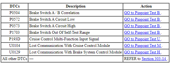
SCCM DTC Chart

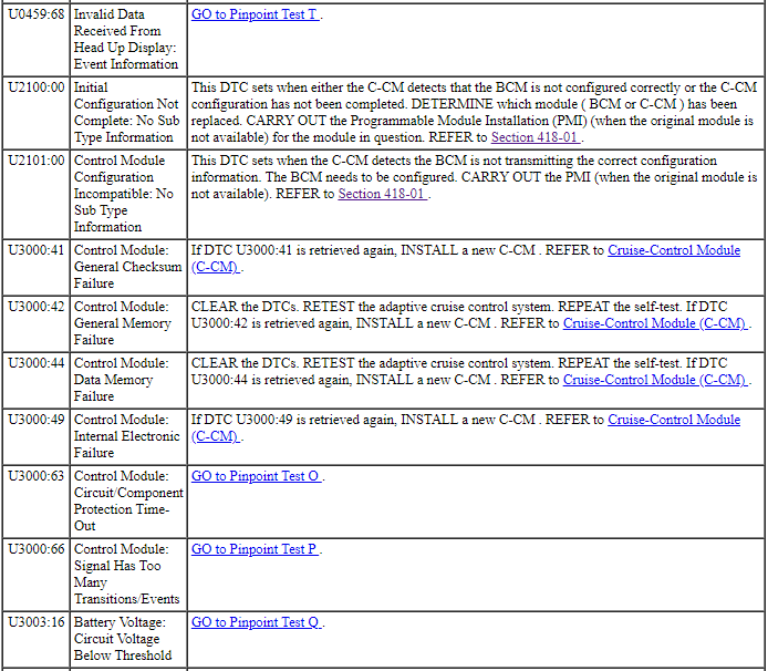
Cruise-Control Module (C-CM) DTC Chart
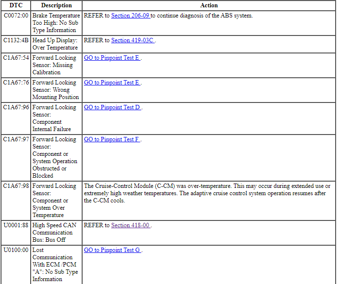
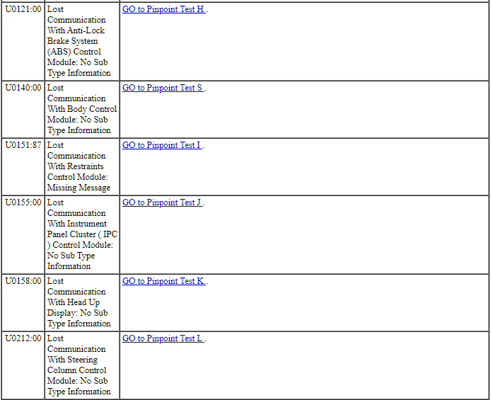
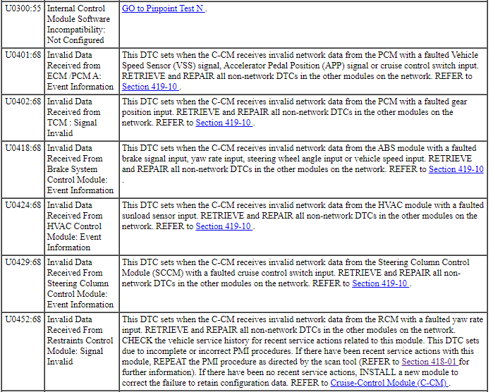

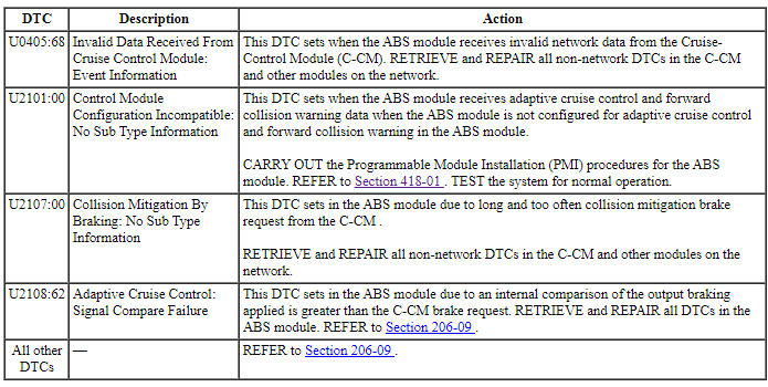
ABS Module DTC Chart
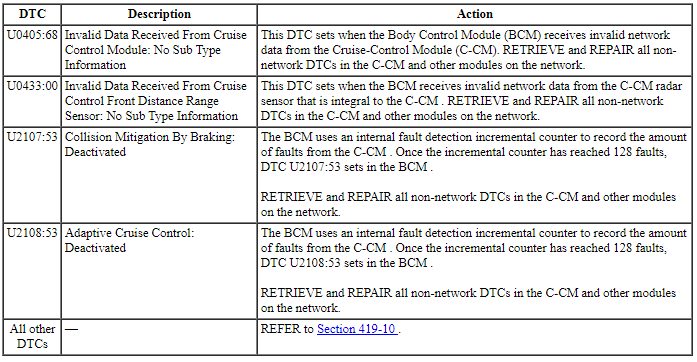
BCM DTC Chart
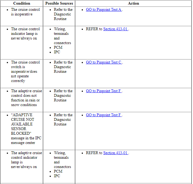
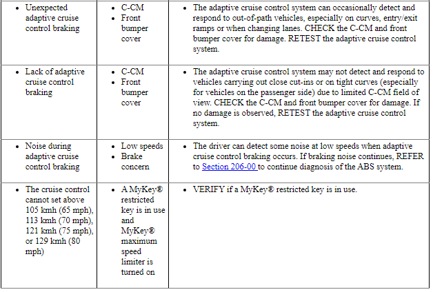
Symptom Chart
Diagnostics in this manual assume a certain skill level and knowledge of Ford-specific diagnostic practices. Refer to Diagnostic Methods in Section 100-00 for information about these practices.
NOTE: Refer to Description and Operation, Intelligent Access (IA) with Push Button Start in Section 419-01C to review the procedures for achieving the various ignition states (ignition in accessory, ignition on, ignition start, ignition off) on vehicles with this feature.
Pinpoint Tests
Pinpoint Test A: The Cruise Control Is Inoperative
Diagnostic Overview
Diagnostics in this manual assume a certain skill level and knowledge of Ford-specific diagnostic practices. Refer to Diagnostic Methods in Section 100-00 for information about these practices.
Normal Operation and Fault Conditions
REFER to Adaptive Cruise Control Operation in Cruise Control.
REFER to Steering Wheel Switch Function in Cruise Control.
REFER to Steering Wheel Switches in Section 211-05.
-
Possible Sources
- Wiring, terminals and connectors
- Cruise control switches (part of the message center switch)
- Cruise control deactivator switch (integral to the stoplamp switch)
- Digital TR sensor
- Stoplamp switch
- Vehicle speed signal
- ABS module
- BCM
- C-CM
- PCM
- SCCM
PINPOINT TEST A: THE CRUISE CONTROL IS INOPERATIVE
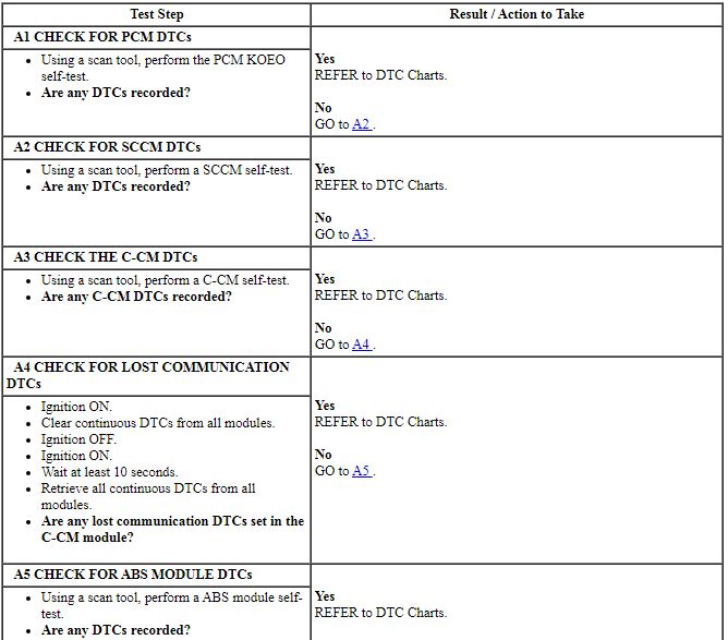
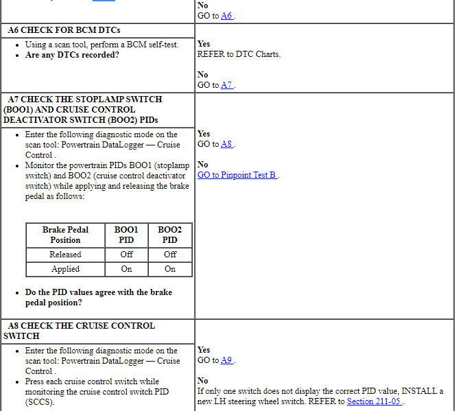
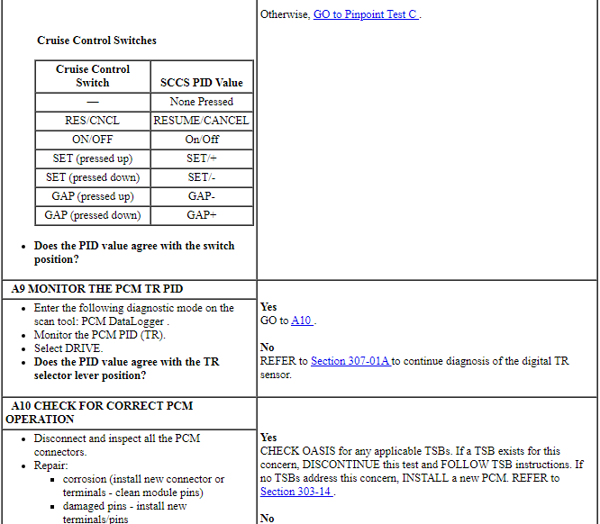

Pinpoint Test B: DTC P0504, P0572, P0573 Or P1703
Diagnostic Overview
Diagnostics in this manual assume a certain skill level and knowledge of Ford-specific diagnostic practices. Refer to Diagnostic Methods in Section 100-00 for information about these practices.
Refer to Wiring Diagrams Cell 31, Speed Control for schematic and connector information.
Normal Operation and Fault Conditions
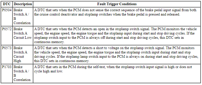
REFER to Brake Switch in Cruise Control.
DTC Fault Trigger Conditions
-
Possible Sources
- Wiring, terminals and connectors
- Stoplamp switch
- PCM
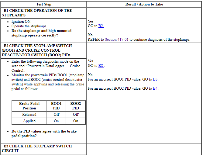
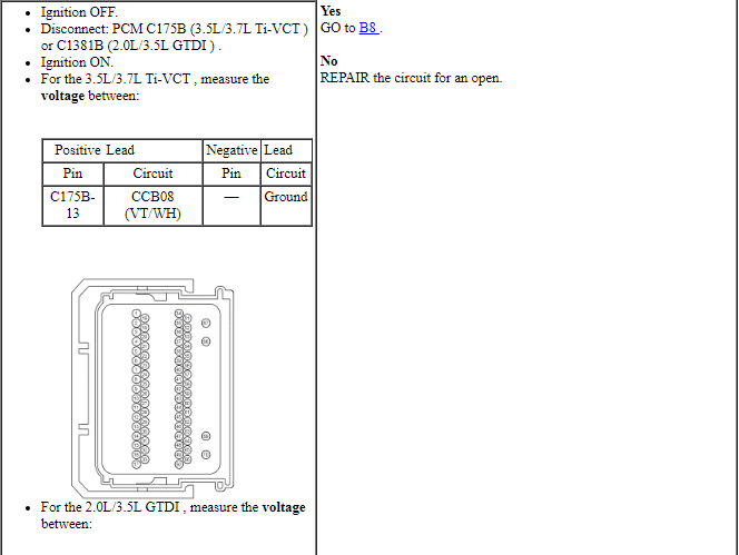
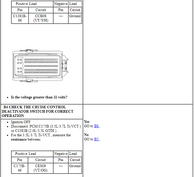
PINPOINT TEST B: DTC P0504, P0572, P0573 OR P1703
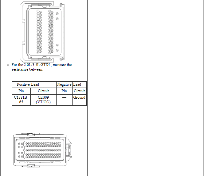
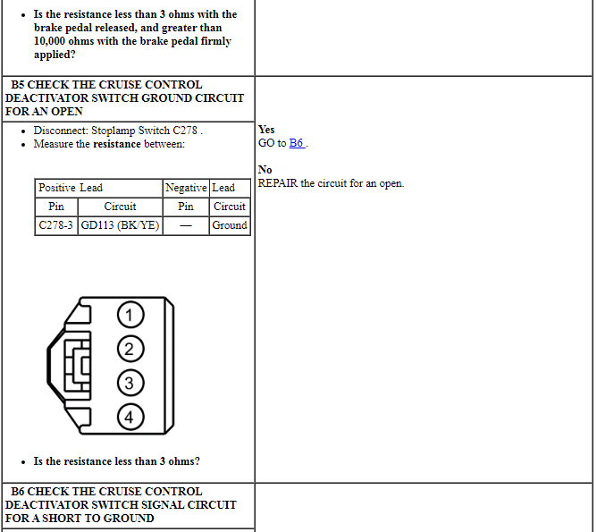
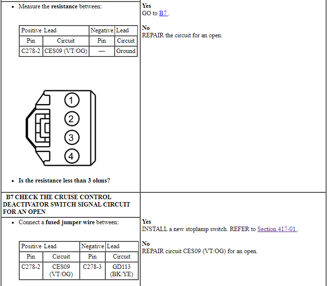
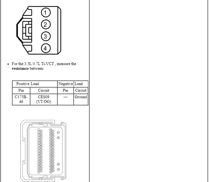
NOTICE: Use the correct probe adapter(s) when making measurements. Failure to use the correct probe adapter(s) may damage the connector.
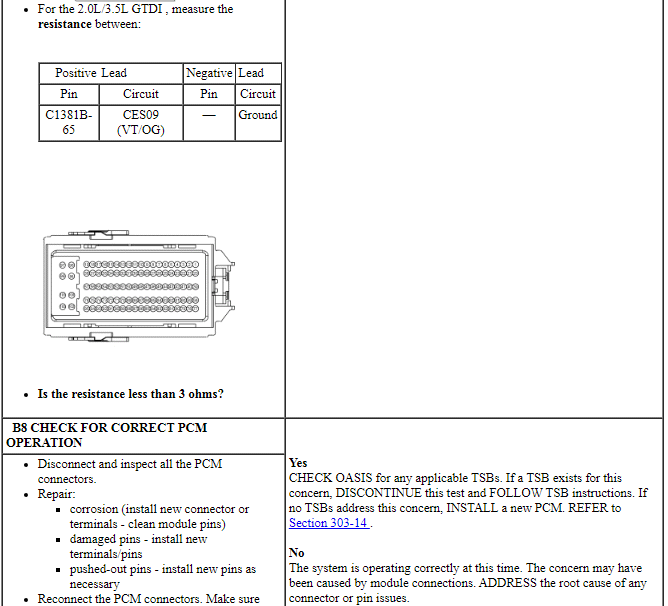

Pinpoint Test C: The Cruise Control Switch Is Inoperative/Does Not Operate Correctly
Diagnostic Overview
Diagnostics in this manual assume a certain skill level and knowledge of Ford-specific diagnostic practices. Refer to Diagnostic Methods in Section 100-00 for information about these practices.
Refer to Wiring Diagrams Cell 31, Speed Control for schematic and connector information.
Normal Operation and Fault Conditions
REFER to Steering Wheel Switch Function in Cruise Control.
REFER to Steering Wheel Switches in Cruise Control.
DTC Fault Trigger Conditions

-
Possible Sources
- Wiring, terminals and connectors
- Clockspring
- Cruise control switches (part of the message center switch)
- SCCM
PINPOINT TEST C: THE CRUISE CONTROL SWITCH IS INOPERATIVE/DOES NOT OPERATE CORRECTLY
NOTICE: Use the correct probe adapter(s) when making measurements. Failure to use the correct probe adapter(s) may damage the connector.
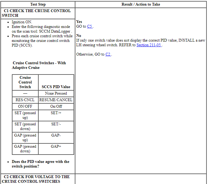
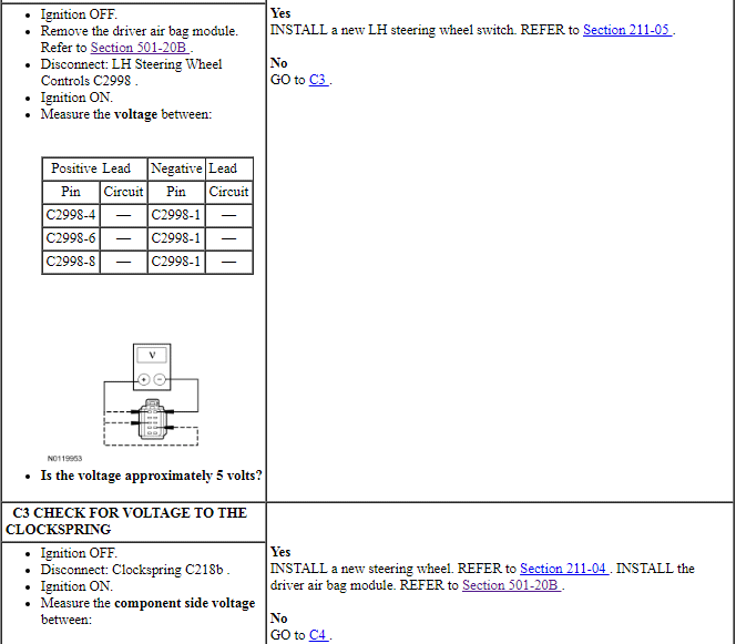
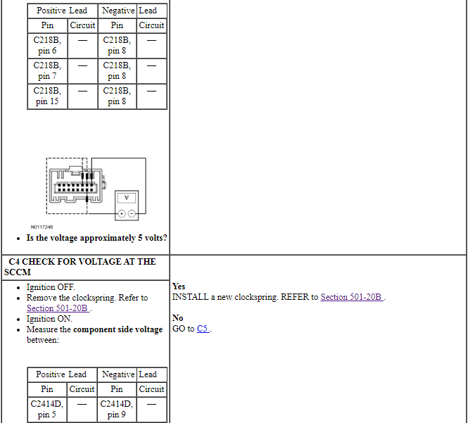
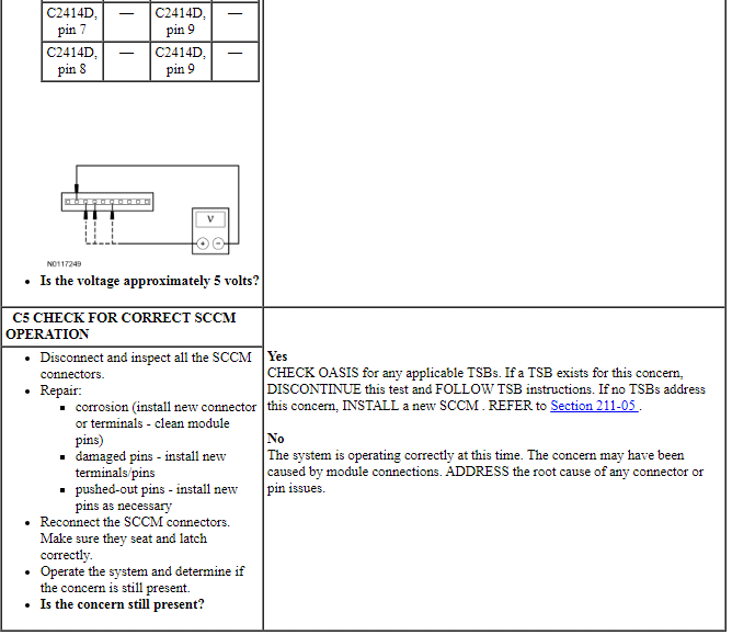
Pinpoint Test D: DTC C1A67:96
Diagnostic Overview
Diagnostics in this manual assume a certain skill level and knowledge of Ford-specific diagnostic practices. Refer to Diagnostic Methods in Section 100-00 for information about these practices.
DTC Fault Trigger Conditions

-
Possible Sources
- C-CM
PINPOINT TEST D: DTC C1A67:96
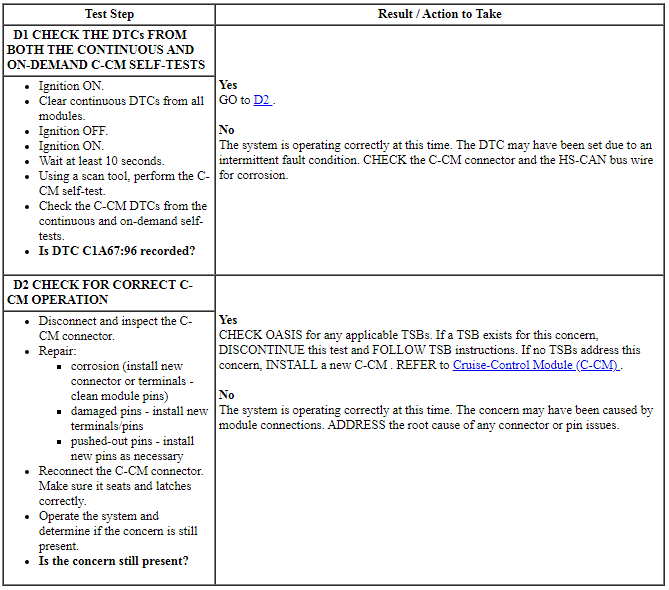
Pinpoint Test E: DTC C1A67:54 Or DTC C1A67:76
Diagnostic Overview
Diagnostics in this manual assume a certain skill level and knowledge of Ford-specific diagnostic practices. Refer to Diagnostic Methods in Section 100-00 for information about these practices.
DTC Fault Trigger Conditions

-
Possible Sources
- C-CM alignment
- C-CM mounting bracket
- C-CM
PINPOINT TEST E: DTC C1A67:54 OR DTC C1A67:76
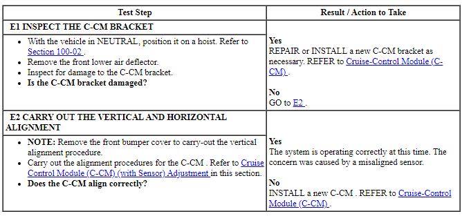
Pinpoint Test F: The Adaptive Cruise Control Does Not Function In Rain Or Snow Conditions
Diagnostic Overview
Diagnostics in this manual assume a certain skill level and knowledge of Ford-specific diagnostic practices. Refer to Diagnostic Methods in Section 100-00 for information about these practices.
DTC Fault Trigger Conditions
-
Possible Sources
- Front bumper cover
- Blockage or obstruction
- C-CM mounting bracket
- C-CM alignment
- C-CM
PINPOINT TEST F: THE ADAPTIVE CRUISE CONTROL DOES NOT FUNCTION IN RAIN OR SNOW CONDITIONS
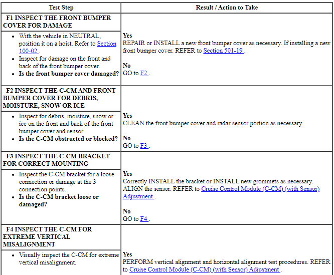
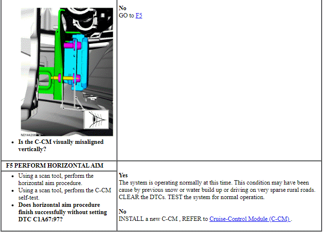
Pinpoint Test G: DTC U0100:00
Diagnostic Overview
Diagnostics in this manual assume a certain skill level and knowledge of Ford-specific diagnostic practices. Refer to Diagnostic Methods in Section 100-00 for information about these practices.
DTC Fault Trigger Conditions

-
Possible Sources
- C-CM
- PCM
PINPOINT TEST G: DTC U0100:00
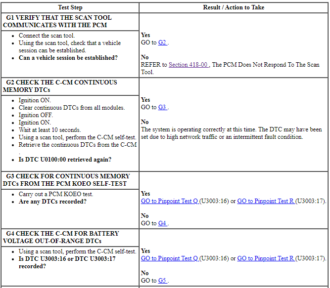

Pinpoint Test H: DTC U0121:00 Or DTC U0129
Diagnostic Overview
Diagnostics in this manual assume a certain skill level and knowledge of Ford-specific diagnostic practices. Refer to Diagnostic Methods in Section 100-00 for information about these practices.
DTC Fault Trigger Conditions

-
Possible Sources
- ABS module
- C-CM
PINPOINT TEST H: DTC U0121:00 OR DTC U0129
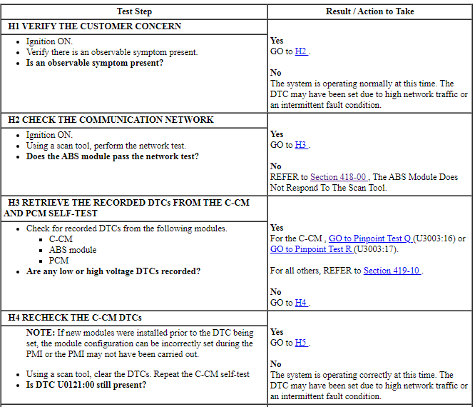

Pinpoint Test I: DTC U0151:87
Diagnostic Overview
Diagnostics in this manual assume a certain skill level and knowledge of Ford-specific diagnostic practices. Refer to Diagnostic Methods in Section 100-00 for information about these practices.
DTC Fault Trigger Conditions

-
Possible Sources
- C-CM
- RCM
PINPOINT TEST I: DTC U0151:87
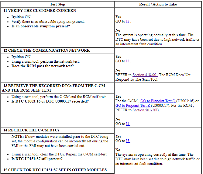

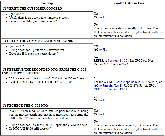
Pinpoint Test J: DTC U0155:00
Diagnostic Overview
Diagnostics in this manual assume a certain skill level and knowledge of Ford-specific diagnostic practices. Refer to Diagnostic Methods in Section 100-00 for information about these practices.
DTC Fault Trigger Conditions

-
Possible Sources
- C-CM
- IPC
PINPOINT TEST J: DTC U0155:00

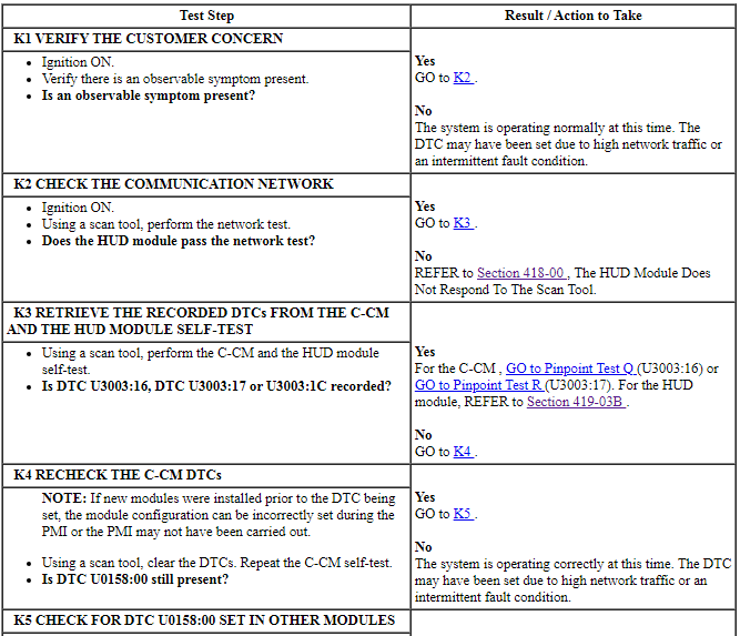
Pinpoint Test K: DTC U0158:00
Diagnostic Overview
Diagnostics in this manual assume a certain skill level and knowledge of Ford-specific diagnostic practices. Refer to Diagnostic Methods in Section 100-00 for information about these practices.
DTC Fault Trigger Conditions

-
Possible Sources
- C-CM
- HUD module
PINPOINT TEST K: DTC U0158:00

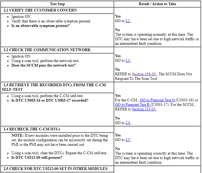
Pinpoint Test L: DTC U0212:00
Diagnostic Overview
Diagnostics in this manual assume a certain skill level and knowledge of Ford-specific diagnostic practices. Refer to Diagnostic Methods in Section 100-00 for information about these practices.
DTC Fault Trigger Conditions

-
Possible Sources
- C-CM
- SCCM
PINPOINT TEST L: DTC U0212:00

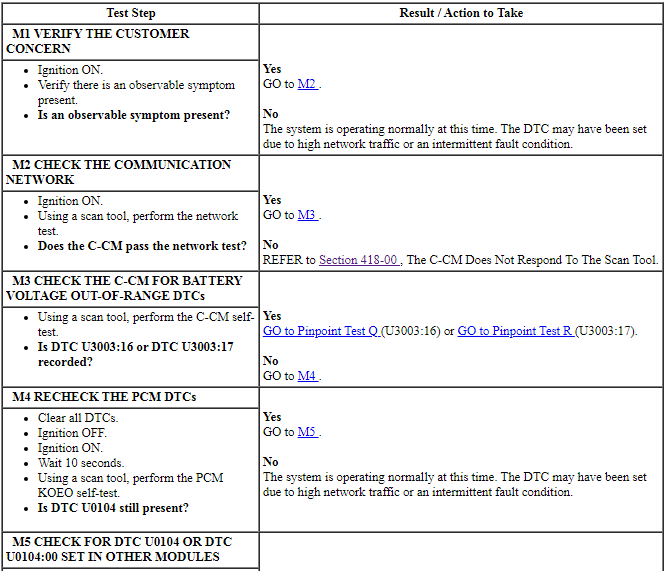
Pinpoint Test M: DTC U0104
Diagnostic Overview
Diagnostics in this manual assume a certain skill level and knowledge of Ford-specific diagnostic practices. Refer to Diagnostic Methods in Section 100-00 for information about these practices.
DTC Fault Trigger Conditions

-
Possible Sources
- C-CM
- PCM
PINPOINT TEST M: DTC U0104

Pinpoint Test N: DTC U0300:55
Diagnostic Overview
Diagnostics in this manual assume a certain skill level and knowledge of Ford-specific diagnostic practices. Refer to Diagnostic Methods in Section 100-00 for information about these practices.
Normal Operation and Fault Conditions
REFER to Adaptive Cruise Control (ACC) Operation in Cruise Control.
The C-CM can be aligned both vertically and horizontally. The vertical alignment is a manual procedure carried out by adjusting the C-CM adjustment screw. The horizontal alignment is a software procedure that is carried out internal to the C-CM.
DTC Fault Trigger Conditions

-
Possible Sources
- Front bumper cover
- C-CM alignment
- C-CM mounting bracket
- C-CM
PINPOINT TEST N: DTC U0300:55
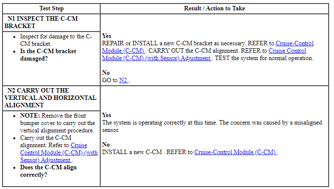
Pinpoint Test O: DTC U3000:63
Diagnostic Overview
Diagnostics in this manual assume a certain skill level and knowledge of Ford-specific diagnostic practices. Refer to Diagnostic Methods in Section 100-00 for information about these practices.
DTC Fault Trigger Conditions

-
Possible Sources
- Front bumper cover
- C-CM mounting bracket
- C-CM
PINPOINT TEST O: DTC U3000:63
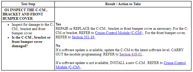
Pinpoint Test P: DTC U3000:66
Diagnostic Overview
Diagnostics in this manual assume a certain skill level and knowledge of Ford-specific diagnostic practices. Refer to Diagnostic Methods in Section 100-00 for information about these practices.
DTC Fault Trigger Conditions

-
Possible Sources
- ABS module
- C-CM
- PCM
PINPOINT TEST P: DTC U3000:66
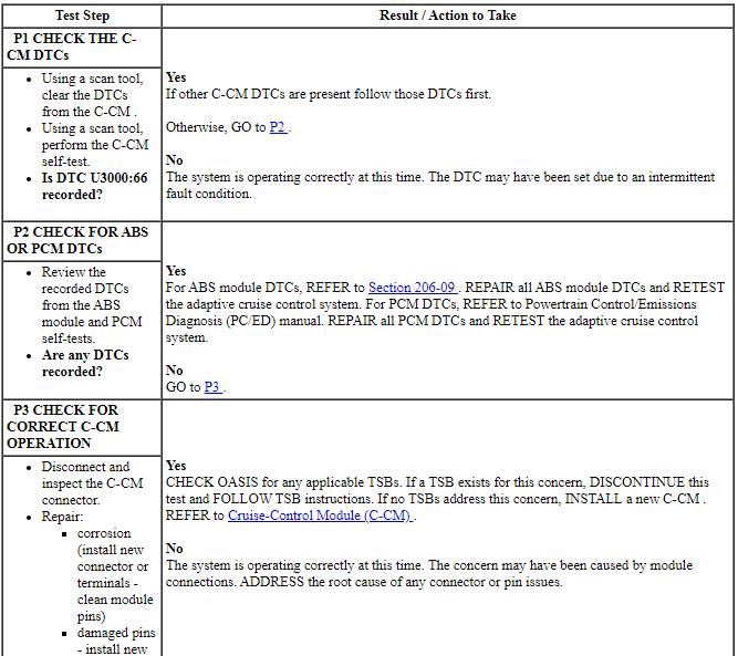
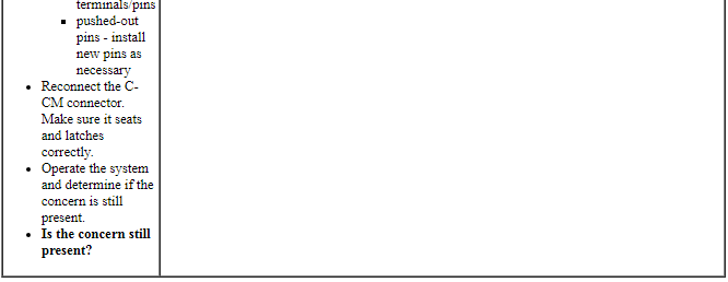
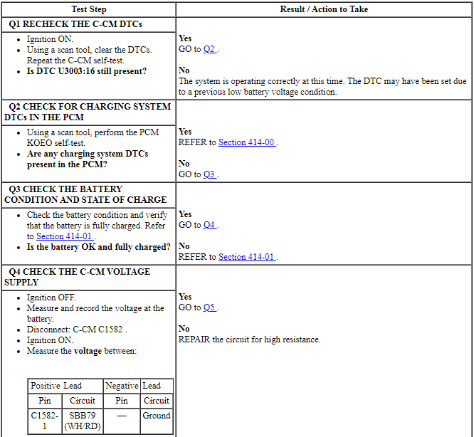
Pinpoint Test Q: DTC U3003:16
Diagnostic Overview
Diagnostics in this manual assume a certain skill level and knowledge of Ford-specific diagnostic practices. Refer to Diagnostic Methods in Section 100-00 for information about these practices.
Refer to Wiring Diagrams Cell 31, Cruise Control for schematic and connector information.
DTC Fault Trigger Conditions

-
Possible Sources
- Wiring, terminals and connectors
- Battery
- Generator
- C-CM
- PCM
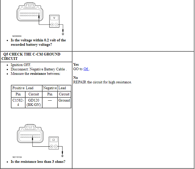
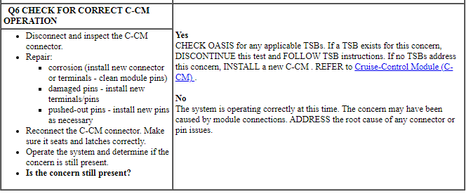
PINPOINT TEST Q: DTC U3003:16
NOTICE: Use the correct probe adapter(s) when making measurements. Failure to use the correct probe adapter(s) may damage the connector.
NOTE: Failure to disconnect the battery when instructed results in false resistance readings. Refer to Section 414-01.
Pinpoint Test R: DTC U3003:17
Diagnostic Overview
Diagnostics in this manual assume a certain skill level and knowledge of Ford-specific diagnostic practices. Refer to Diagnostic Methods in Section 100-00 for information about these practices.
DTC Fault Trigger Conditions

-
Possible Sources
- Wiring, terminals and connectors
- Battery
- Generator
- C-CM
- PCM
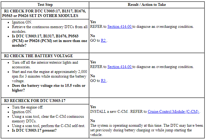
PINPOINT TEST R: DTC U3003:17
NOTE: DTC U3003:17 may be stored in the module memory due to past battery charging or vehicle jump starting events.
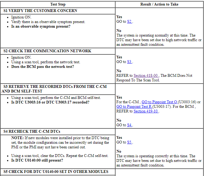
Pinpoint Test S: DTC U0140:00
Diagnostic Overview
Diagnostics in this manual assume a certain skill level and knowledge of Ford-specific diagnostic practices. Refer to Diagnostic Methods in Section 100-00 for information about these practices.
DTC Fault Trigger Conditions

-
Possible Sources
- BCM
- C-CM
PINPOINT TEST S: DTC U0140:00

Pinpoint Test T: DTC U0459:68
Diagnostic Overview
Diagnostics in this manual assume a certain skill level and knowledge of Ford-specific diagnostic practices. Refer to Diagnostic Methods in Section 100-00 for information about these practices.
Normal Operation and Fault Conditions
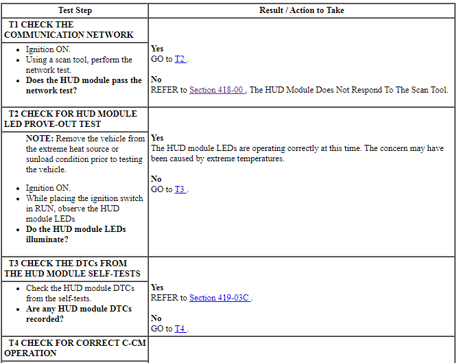
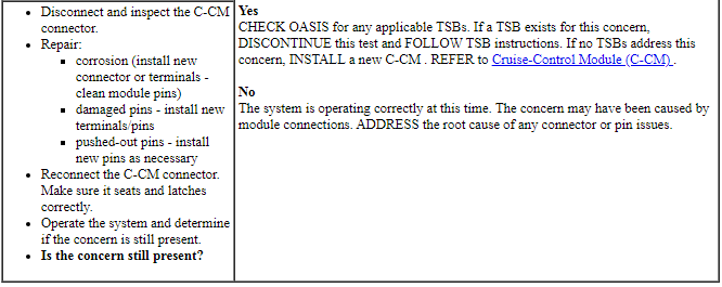
The Head Up Display (HUD) module is designed with a temperature sensor internal to the module. Due to extremely hot weather conditions, the temperature sensor circuit allows the HUD module to disable under high temperature conditions, which could damage the HUD module LEDs. The HUD module is designed with a LED prove-out test. Upon each ignition cycle when the ignition switch is in RUN, the LEDs illuminate for a period of time indicating the HUD module is functional.
DTC Fault Trigger Conditions

-
Possible Sources
- C-CM
- HUD module
PINPOINT TEST T: DTC U0459:68
Pinpoint Test U: DTC P193D
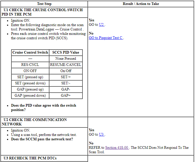
Diagnostic Overview
Diagnostics in this manual assume a certain skill level and knowledge of Ford-specific diagnostic practices. Refer to Diagnostic Methods in Section 100-00 for information about these practices.
DTC Fault Trigger Conditions

-
Possible Sources
- Cruise control switches (part of the message center switch)
- SCCM
- PCM
PINPOINT TEST U: DTC P193D
GENERAL PROCEDURES
Cruise Control Module (C-CM) (with Sensor) Adjustment
Vertical Alignment
NOTE: In order to align the Cruise-Control Module (C-CM), which is a radar sensor unit, the vehicle must be in a wheel alignment bay station so that the vehicle is level.
NOTE: Damage to the C-CM bracket may affect correct alignment. When aligning the C-CM, inspect the C-CM bracket for damage and repair as necessary before carrying out the alignment procedure.
- Place the vehicle on a wheel alignment bay station.
- Remove the C-CM radar sensor unit fascia cover.
- Locate the C-CM radar sensor alignment screw.
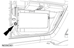
- Place a combination square level on the face of the C-CM radar sensor unit and check alignment.
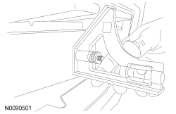
- Keeping the combination square level on the face of the C-CM radar sensor unit, adjust the pitch of the sensor by using an E5 inverted Torx bit to adjust the screw until the sensor is vertical and level.
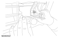
- NOTE: Prior to installing the C-CM radar sensor unit fascia
cover, clean and remove any debris on the front or back of the cover.
Install the C-CM radar sensor unit fascia cover.
Horizontal Alignment
NOTICE: The engine must be running during the this alignment procedure. Failure to leave the engine running throughout the entire procedure results in the cancellation of the alignment procedure and the system remains non-functional.
NOTE: The horizontal alignment for the cruise control sensor is a software calibration. No manual adjustment is needed for this procedure. The scan tool calibrates the Cruise-Control Module (C-CM) radar sensor unit through the C-CM calibration procedure.
- Follow the scan tool on-screen instructions to carry-out
the C-CM calibration procedure.
- Follow the operating instructions shown on the Integrated Diagnostic System (IDS).
- After completion of the test, verify that the test completed successfully.
- Follow the prompts to drive the vehicle after successful completion of the test. This may take several minutes.
REMOVAL AND INSTALLATION
Cruise-Control Module (C-CM)
Removal
NOTE: The vertical and horizontal alignment procedures need to be carried out to align the sensor.
Cruise-Control Module (C-CM) or bracket
- With the vehicle in NEUTRAL, position it on a hoist. For additional information, refer to Section 100-02.
- Remove the front bumper cover. For additional information, refer to Section 501-19.
- NOTE: Gently pry to release the C-CM from the retaining studs
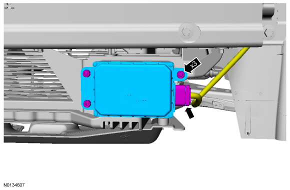
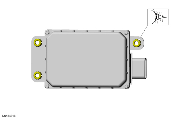
- NOTE: If one plastic grommet is damaged C-CM, a new grommet should be installed.
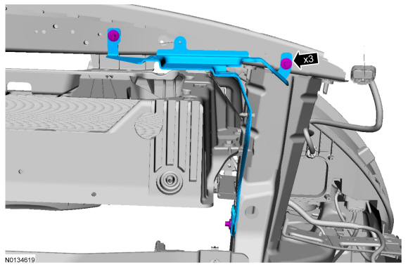
Bracket
Installation
Bracket
-
- Tighten the bolts to 8 Nm (71 lb-in).
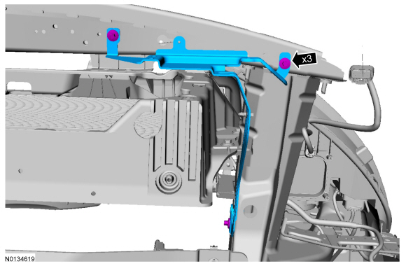
C-CM or bracket
NOTE: The vertical and horizontal alignment procedures need to be carried out to align the sensor.
- NOTE: If one plastic grommet breaks while the C-CM is being
installed, a new grommet should be installed.
NOTE: Firmly apply pressure to the C-CM so that it seats completely in the grommets.
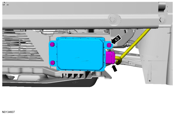
- Once the C-CM is installed, pull the C-CM to confirm that all 3 ball studs are fully seated in the grommets.
- Connect the C-CM connector.
- NOTE: Do not install the C-CM front bumper cover until the
alignment procedures are carried out.
Vertically and horizontally align the C-CM. For additional information, refer to Cruise Control Module (C-CM) (with Sensor) Adjustment in this section.
- Install the front bumper cover. For additional information, refer to Section 501-19.
 Cruise Control - Non-Adaptive
DESCRIPTION AND OPERATION
Cruise Control
Overview
The cruise control system is controlled by the PCM. The cruise control mode
is selected from the steering wheel mounted switches (ON/OFF, SET, CNCL a ...
 Collision Avoidance
DESCRIPTION AND OPERATION
Forward Collision Warning
Overview
The forward collision warning system alerts the driver of a collision risk
with a red warning LED indicator bar located above the instrume ...
Other materials:
Removal and Installation
Headlamp Assembly
Removal
Remove the front bumper cover. Refer to Section 501-19.
Remove the headlamp assembly upper bolt.
To install, tighten to 3.2 Nm (28 lb-in).
Remove the headlamp assembly front bolt.
To install, tighten to 3.2 Nm (28 lb-in).
Remove the headlamp ...
Diagnosis and Testing
External Controls
Inspection and Verification
Verify the customer concern by operating the system.
Visually inspect for obvious signs of mechanical or electrical damage.
If the concern is not visually evident, verify the symptom. GO
to Symptom Chart.
Visual Inspection Chart
DTC Char ...
Specifications, Description and Operation
SPECIFICATIONS
Material
Torque Specifications
DESCRIPTION AND OPERATION
Handles, Locks, Latches and Entry Systems
Overview
The power lock/unlock feature locks or unlocks the doors upon a customer
request from either door lock control switch in the vehicle, a RKE transmitter,
or the key ...
