DESCRIPTION AND OPERATION
Cruise Control
Overview
The cruise control system is controlled by the PCM. The cruise control mode is selected from the steering wheel mounted switches (ON/OFF, SET, CNCL and RES) which are integrated into the LH steering wheel switch. The cruise control system maintains a selected vehicle speed between 37 kmh (23 mph) and the maximum limited vehicle speed. When a MyKey restricted key is in use and maximum speed limiter is turned on, vehicle speed is limited. The maximum vehicle speed can be set to 105 kmh (65 mph), 113 kmh (70 mph), 121 kmh (75 mph), or 129 kmh (80 mph). During normal driving, the vehicle speed can vary slightly from the set speed due to road conditions. The vehicle speed can fluctuate when driving up and down a steep hill. If the vehicle speed decreases more than 16.1 kmh (10 mph) below the set speed, the cruise control disengages.
System Operation
System Diagram
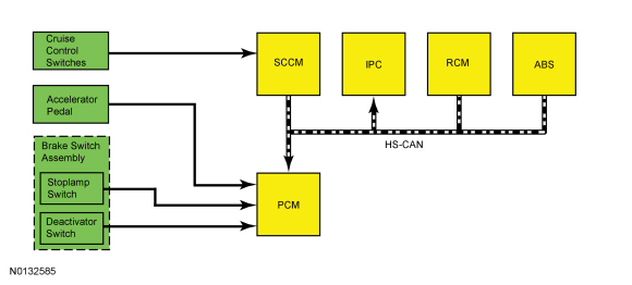
Network Message Chart
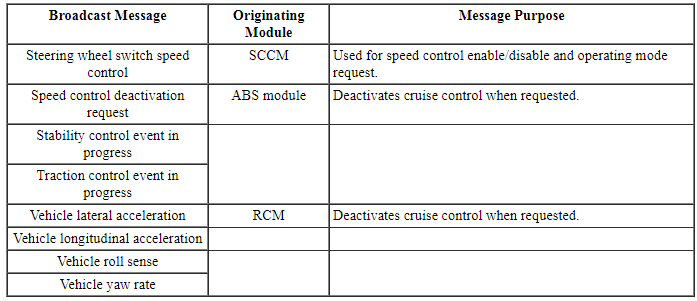
Module Network Input Messages - IPC
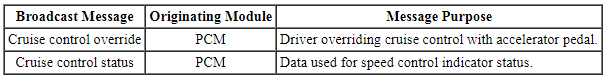
Module Network Input Messages - PCM
Cruise Control Operation
The cruise control functions include:
- turning on the cruise control system.
- setting and maintaining the desired vehicle speed.
- accelerating the vehicle speed.
- coasting down to a lower speed.
- resuming the prior vehicle speed.
- turning off the cruise control system.
Hardwired inputs to the PCM are:
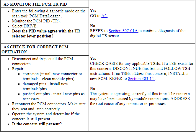
- Digital TR sensor
- Stoplamp switch
- Cruise control deactivator switch (integral to the stoplamp switch)
- APP sensor
Hardwired outputs of the PCM are:
- ETB command
The vehicle speed is controlled by the PCM through the ETC subsystem.
The cruise control system provides self-diagnostics. Cruise control is disabled anytime an error is detected in the system. No IPC indicator or message center messages are displayed when faults occur. Fault codes are logged by the PCM or SCCM.
An ETC system fault also causes the cruise control system to be disabled. In this case, an ETC system powertrain malfunction (wrench) warning indicator is displayed.
Additionally, certain conditions cause the cruise control system to deactivate:
- Application of the parking brake
- Transmission gear selector is put into a position other than D or OD
- Cruise control set speed is overridden with the accelerator pedal for a period longer than 5 minutes
- Cruise control switch is pressed or stuck longer than 2 minutes
- ABS fault
Cruise Control Indicator
The cruise control indicator, located in the IPC, illuminates gray to indicate the cruise control system is in standby mode. The cruise control indicator illuminates green to indicate the cruise control system is active.
Steering Wheel Switch Function
Pressing up (ON) and releasing the ON/OFF switch turns the cruise control system on. Pressing up (SET+) or down (SET-) on the SET switch while the vehicle is traveling at the desired speed activates the cruise control system.
Pressing up or down on the SET switch while in the active mode increases or decreases the maintained vehicle speed by 2 kmh per press when displayed units are "kmp" and 1 mph per press when displayed units are "mph". If the respective switch is pressed and held, the vehicle speed continues to accelerate or decelerate until the switch is released.
Pressing down (OFF) and releasing the ON/OFF switch, or turning the ignition switch to the OFF position, turns the cruise control system off. While the cruise control system is active, applying the brake pedal or pressing the CNCL (CANCEL) switch puts the cruise control system into standby mode. Pressing the RES (RESUME) switch when the cruise control system is in standby mode causes the vehicle to accelerate to the last set speed. Resume does not function if the OFF switch is pressed, the ignition switch is cycled OFF, or if the current vehicle speed is below the minimum operational speed.
Cruise Control Deactivation Event Parameter Identification (PIDs)
NOTE: When recording deactivation event PIDs, turn the cruise control OFF immediately after the deactivation event occurs to prevent recording additional deactivation events which do not apply to the fault present.
NOTE: Cruise control deactivation PIDs are not available on the 2.0L GTDI engine.
The PCM has PIDs available, through the powertrain DataLogger, that indicate the event that caused the last cruise control deactivation. When the cruise control is turned ON, all current deactivation (or non-activation) conditions are recorded. When the cruise control is turned OFF, event recording stops. The recorded events are stored until the ignition is turned OFF.
The PCM has 24 cruise control deactivation event PIDs, identified as CRUISEOFF_00 through 24. The event PIDs should be read when deactivation or non-activation exists.
Component Description
Steering Wheel Switches
The cruise control steering wheel mounted switches are momentary contact switches that toggle up and down for the switch state. The switches are an input to the SCCM.
Brake Switch
When the brake pedal is applied, an electrical signal from the stoplamp circuit to the PCM deactivates the system. Under increased brake pedal effort, the cruise control deactivator switch opens and removes the ground signal from the PCM input circuit, releasing the throttle immediately deactivating the system.
DIAGNOSIS AND TESTING
Cruise Control
DTC Charts
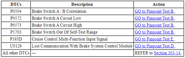
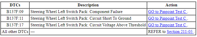
PCM DTC Chart
SCCM DTC Chart
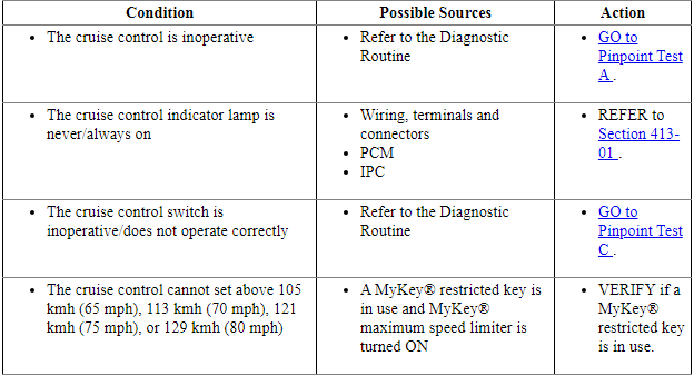
Symptom Chart
Pinpoint Tests
Pinpoint Test A: The Cruise Control Is Inoperative
Diagnostic Overview
Diagnostics in this manual assume a certain skill level and knowledge of Ford-specific diagnostic practices. Refer to Diagnostic Methods in Section 100-00 for information about these practices.
Normal Operation and Fault Conditions
REFER to Cruise Control Operation in Cruise Control.
REFER to Steering Wheel Switch Function in Cruise Control.
REFER to Steering Wheel Switches in Section 211-05.
-
Possible Sources
- Wiring, terminals and connectors
- PCM not configured for cruise control
- Cruise control switch
- Digital TR sensor
- Vehicle speed signal
- PCM
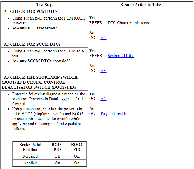
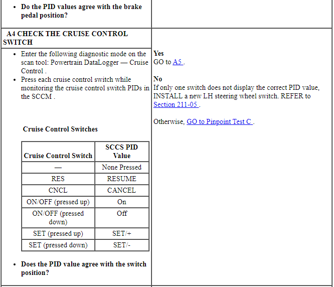
PINPOINT TEST A: THE CRUISE CONTROL IS INOPERATIVE
Pinpoint Test B: DTC P0504, P0572, P0573 Or P1703
Diagnostic Overview
Diagnostics in this manual assume a certain skill level and knowledge of Ford-specific diagnostic practices. Refer to Diagnostic Methods in Section 100-00 for information about these practices.
Refer to Wiring Diagrams Cell 31, Speed Control for schematic and connector information.
Normal Operation and Fault Conditions
REFER to Brake Switch in Cruise Control.
DTC Fault Trigger Conditions
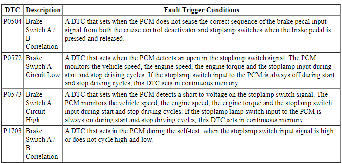
-
Possible Sources
- Wiring, terminals and connectors
- Stoplamp switch
- PCM
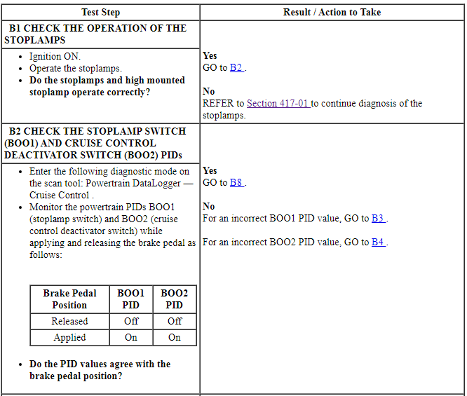
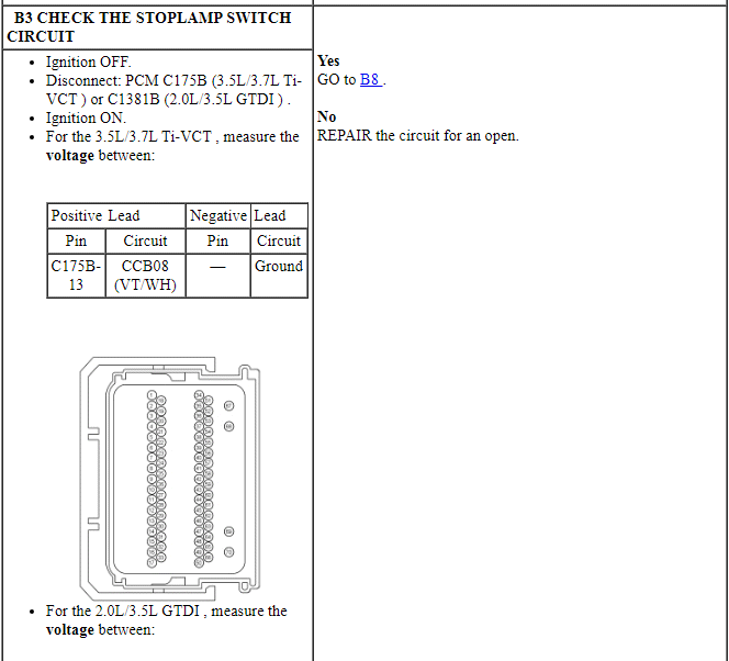
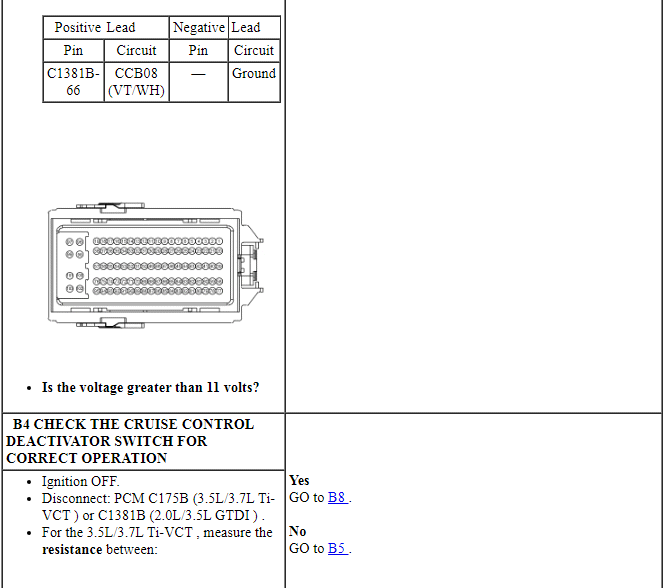
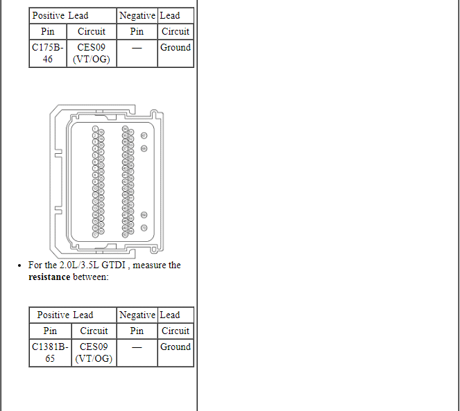
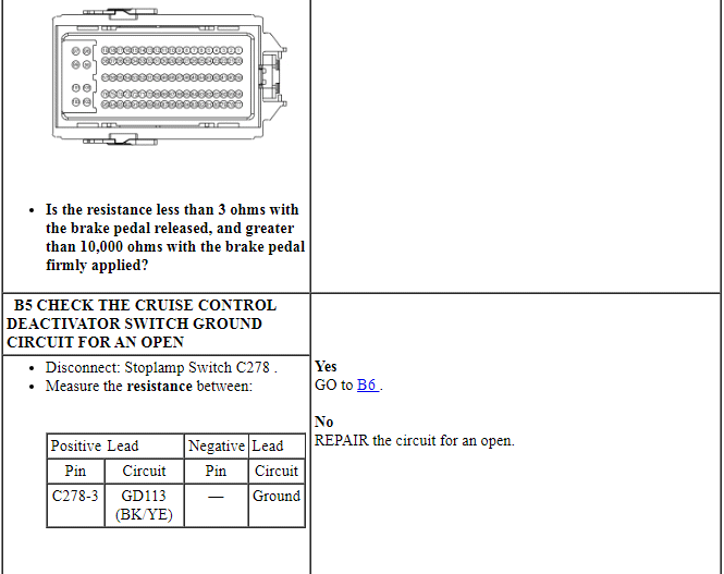
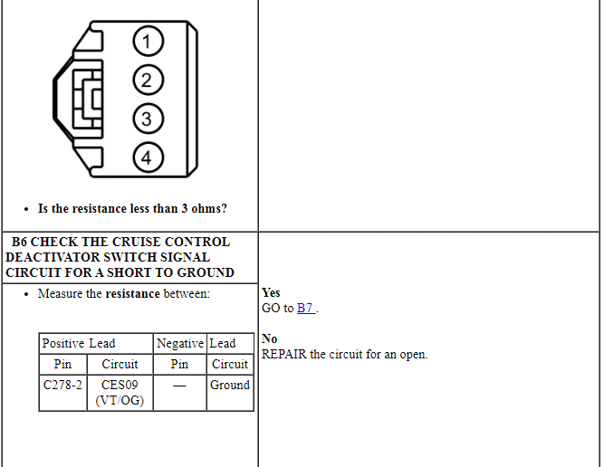
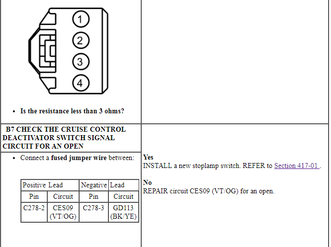
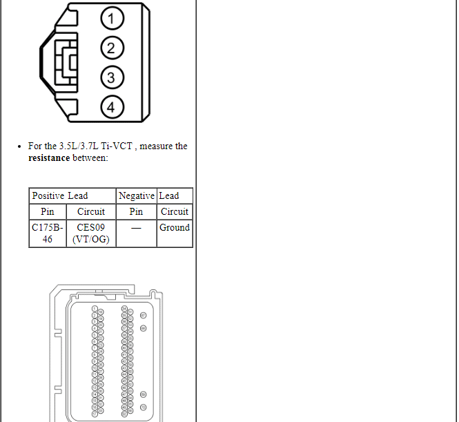
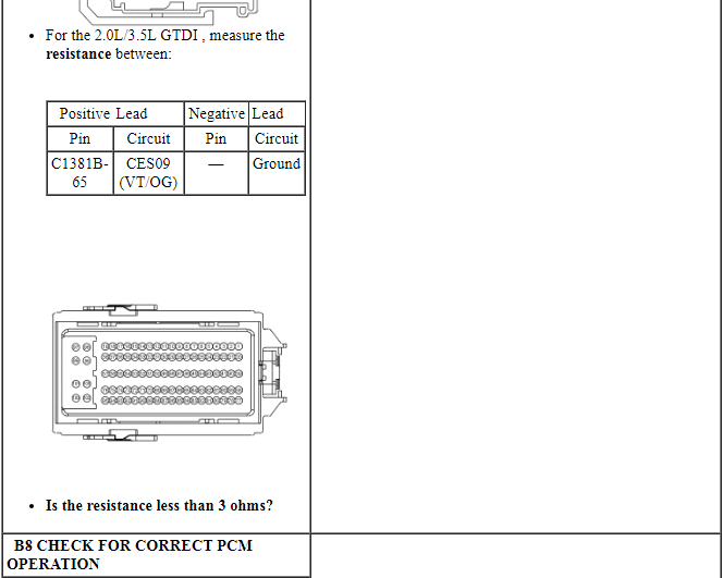
PINPOINT TEST B: DTC P0504, P0572, P0573 OR P1703
NOTICE: Use the correct probe adapter(s) when making measurements. Failure to use the correct probe adapter(s) may damage the connector.
Pinpoint Test C: The Cruise Control Switch Is Inoperative/Does Not Operate Correctly
Diagnostic Overview
Diagnostics in this manual assume a certain skill level and knowledge of Ford-specific diagnostic practices. Refer to Diagnostic Methods in Section 100-00 for information about these practices.
Refer to Wiring Diagrams Cell 31, Speed Control for schematic and connector information.
Normal Operation and Fault Conditions
REFER to Steering Wheel Switch Function in Cruise Control.
DTC Fault Trigger Conditions
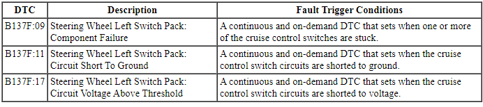
-
Possible Sources
- Wiring, terminals and connectors
- Cruise control switches (part of the message center switch)
- Clockspring
- SCCM
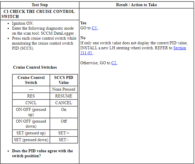
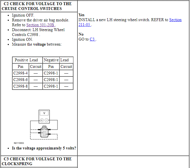
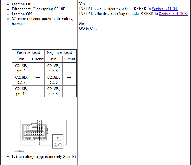
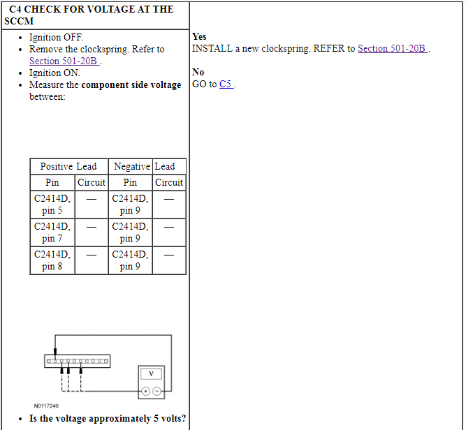
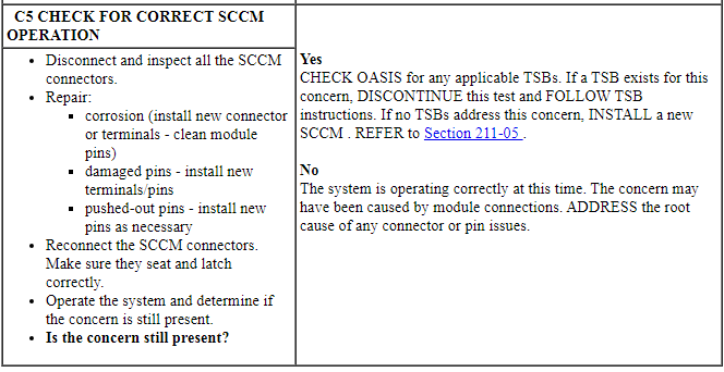
PINPOINT TEST C: THE CRUISE CONTROL SWITCH IS INOPERATIVE/DOES NOT OPERATE CORRECTLY
NOTICE: Use the correct probe adapter(s) when making measurements. Failure to use the correct probe adapter(s) may damage the connector.
Pinpoint Test D: DTC U0129
Diagnostic Overview
Diagnostics in this manual assume a certain skill level and knowledge of Ford-specific diagnostic practices. Refer to Diagnostic Methods in Section 100-00 for information about these practices.
DTC Fault Trigger Conditions
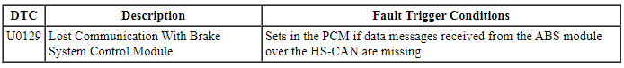
-
Possible Sources
- PCM
- ABS module
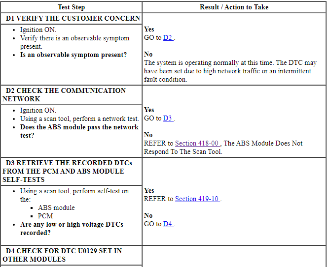
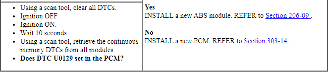
PINPOINT TEST D: DTC U0129
Pinpoint Test E: DTC P193D
Diagnostic Overview
Diagnostics in this manual assume a certain skill level and knowledge of Ford-specific diagnostic practices. Refer to Diagnostic Methods in Section 100-00 for information about these practices.
DTC Fault Trigger Conditions
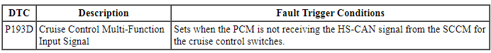
-
Possible Sources
- Cruise control switches (part of the message center switch)
- PCM
- SCCM
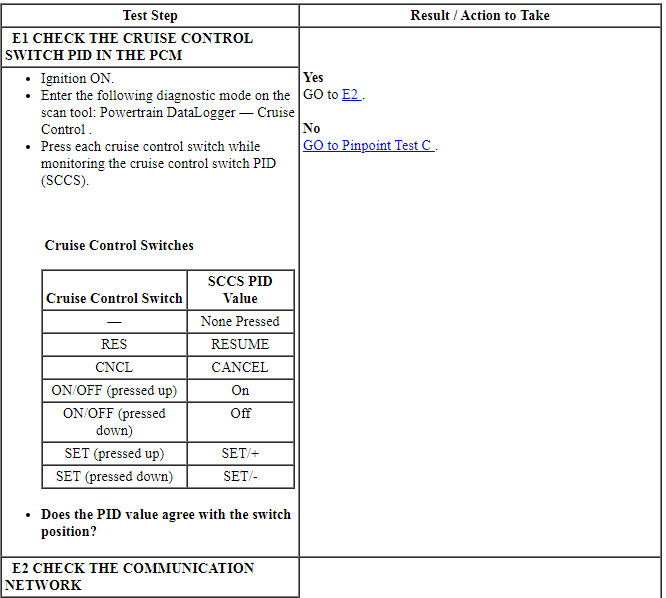
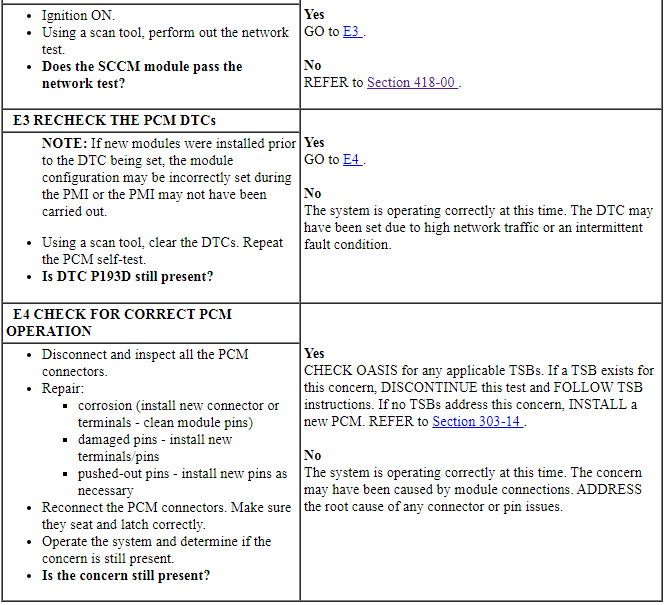
PINPOINT TEST E: DTC P193D
 Remote Convenience
DESCRIPTION AND OPERATION
Universal Transmitter
Overview
The universal transmitter operates garage doors, gates and home or office
lighting and security systems.
System Operation
Universal Home Trans ...
 Cruise Control - Adaptive
SPECIFICATIONS
Torque Specifications
DESCRIPTION AND OPERATION
Cruise Control
Component Location
C-CM
HUD module
Overview
The adaptive cruise control system is controlled by the steeri ...
Other materials:
Emission control system
WARNING: Do not park, idle, or drive your vehicle in dry grass
or other dry ground cover. The emission system heats up the
engine compartment and exhaust system, which can start a fire.
WARNING: Exhaust leaks may result in entry of harmful and
potentially lethal fumes into the passenger compartm ...
Lane keeping system
WARNING: The system is designed to aid the driver. It is
not intended to replace the driverŌĆÖs attention and judgment.
The driver is still responsible to drive with due care and attention.
The system detects unintentional drifting toward the outside of the lane
and alerts and/or aids the driv ...
Air filter(s)
WARNING: To reduce the risk of vehicle damage and/or personal
burn injuries, do not start your engine with the air cleaner
removed and do not remove it while the engine is running.
When changing the air filter element, use only the air filter element
listed. Refer to Motorcraft® Part Numbers in ...
