DESCRIPTION AND OPERATION
Lane Departure Warning
Overview
The LDW is composed of the lane keeping alert and lane keeping aid functions. The lane keeping alert detects unintentional drifting toward the outside of the lane and alerts the driver to stay in the lane through the EPAS system and IPC display. The lane keeping aid assists the driver by steering the vehicle towards the center of the lane. The system automatically detects and tracks the road lane markings using a camera that is mounted behind the interior rear view mirror.
System Operation
System Diagram
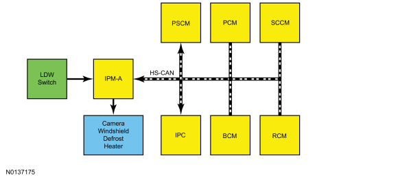
Network Message Chart
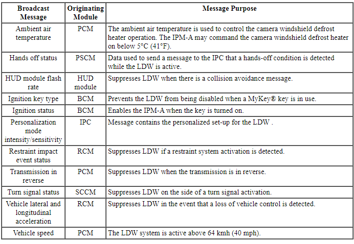
Module Network Input Messages - IPM-A
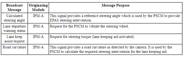
Module Network Input Messages - PSCM
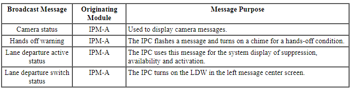
Module Network Input Messages - IPC
Lane Departure Warning (LDW)
NOTE: The IPM-A contains a camera that detects the position of the vehicle in the lane.
The LDW system automatically detects and tracks the road lane markings using a camera that is mounted behind the interior rear view mirror. The system is comprised of the lane keeping aid and lane keeping alert. The lane keeping aid provides steering torque to help the driver keep the vehicle in the lane when a lane departure is detected by the IPM-A. The lane keeping alert generates vibration through the steering wheel when a lane departure is detected by the IPM-A.
The system can be turned on or off by pressing the LDW switch at any time with the key on. The last known settings for mode and on/off are recalled every time the key is turned on. If a MyKey is in use, the system is defaulted to on and cannot be turned off. Only the mode and intensity settings can be changed when a MyKey is present.
The LDW system only activates above 64 kmh (40 mph) and as long as one lane marking can be detected by the camera.
The system can be temporarily suppressed at any time by the following:
- Quick braking
- Fast acceleration
- Using the turn signal indicator
- Evasive steering maneuver
Lane Keeping Alert
The driver alert is generated by the EPAS. When unintended lane departure is detected by the IPM-A, it sends a message to the PSCM, which rapidly oscillates the power steering left to right simulating the vehicle driving on a rumble strip. The intensity of the vibration can be adjusted through the message center.
Lane Keeping Aid
Provides a steering input toward the center of the lane when an unintended lane departure is detected by the IPM-A. The IPM-A provides the road curvature and calculated steering angle inputs to the PSCM. The PSCM then provides steering torque to assist the driver in keeping the vehicle in the center of the lane.
NOTE: The driver can override the lane keeping aid activation at any time.
Hands Off Warning
The PSCM monitors the torque sensor in the EPAS system to determine if a hand is on the steering wheel. If the system detects the driver's hands are not on the wheel after a few seconds, the hands off warning message and chime are generated by the IPC. The PSCM sends the message to the IPM-A and then from the IPM-A to the IPC to request the hands off warning.
The hands off warning has 2 levels of warnings and chime. Level 1 is message center warning only and is triggered after 2 seconds of hands off driving is detected. Level 2 is a message center warning along with a chime, it is an escalation from level 1 and it is triggered after 4 seconds of hands off driving.
NOTE: Depending on the road conditions and the grip/touch on the steering wheel, the LDW system may indicate hands off driving when a hand(s) is on the steering wheel.
System Display
When the lane keeping alert is turned on, an overhead graphic of a vehicle with arrows pointing to the lane markings will be displayed in the LH IPC display. If the lane keeping aid and lane keeping alert are both turned on, a separate white icon will also appear in the IPC. When the system is turned off, the overhead graphic with lane markings are not displayed. The overhead vehicle graphic may still be displayed if adaptive cruise control is enabled.
While the system is on, the color of the arrows pointing to the lane markings will change to indicate the system status as follows:
- Gray: Indicates that the system is temporarily unable to provide an
Alert or Aid activation on the indicated side(s). This may be because:
- the vehicle is under the activation speed
- the turn indicator is active
- the vehicle is in a dynamic maneuver
- the road has no or poor lane markings in the camera field-of-view
- tight curves in the road
- the camera is obscured or unable to detect the lane markings due to environmental conditions (e.g. none or poor lane markings, significant sun angles or shadows, snow, heavy rain, fog)
- Green: Indicates that the system is available or ready to provide an Alert or Aid activation, on the indicated side(s).
- Yellow: Indicates that the system is providing or has just provided a lane keeping aid activation.
- Red: Indicates that the system is providing or has just provided a lane keeping alert activation.
Message Center Settings
The system has 2 optional setting menus available through the IPC message center. To view or adjust them, select Settings > Driver Assist > Lane Keeping Sys in the LH IPC display using the message center switch on the steering wheel. The last known selection for each of these settings is stored by the system. You do not need to readjust the settings each time the key is turned on.
Mode
This setting allows the driver to select which of the system features can enabled and turned on when the LDW switch is pressed.
- Alert only - Provides a steering wheel vibration when an unintended lane departure is detected.
- Aid only - Provides a steering input toward the center of the lane when an unintended lane departure is detected.
- Alert + Aid - Provides both a warning and steering input towards the center of the lane.
Intensity
This setting changes the intensity of the steering wheel vibration used for the lane keeping alert mode. This setting does not impact the lane keeping aid mode.
The 3 settings options are:
- Low
- Medium
- High
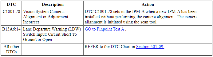
Camera Alignment
Camera alignment is required for the LDW to function correctly. The camera alignment is initiated using the scan tool. Approximately 10 minutes of driving above 64 kmh (40 mph) is required to complete the alignment.
NOTE: The alignment completion is indicated on the scan tool. If the alignment is unsuccessful, check the interior mirror for proper installation.
The IPM-A should be aligned when any of the following occur:
- Windshield replacement
- Change in the tire size
- Suspension work or a wheel alignment
- Vehicle collision where the front air bag(s) deployed
- Mirror/camera replacement
Camera Windshield Defrost Heater
The camera windshield defrost heater is used to defrost the windshield in front of the camera. The IPM-A uses input from the front camera and the ambient air temperature to command the heater. The heater may be commanded on if the ambient temperature is below 5ÂşC (41ÂşF).
Component Description
IPM-A
The IPM-A contains a camera that detects the position of the vehicle in the lane, and is integral to the interior rear view mirror.
LDW Switch
The LDW switch is integral to the active park assist switch. It is a normally open, momentary contact switch that grounds the LDW switch input circuit from the IPM-A when pressed.
DIAGNOSIS AND TESTING
Lane Departure Warning
DTC Charts
Diagnostics in this manual assume a certain skill level and knowledge of Ford-specific diagnostic practices. Refer to Diagnostic Methods in Section 100-00 for information about these practices.
IPM-A DTC Chart
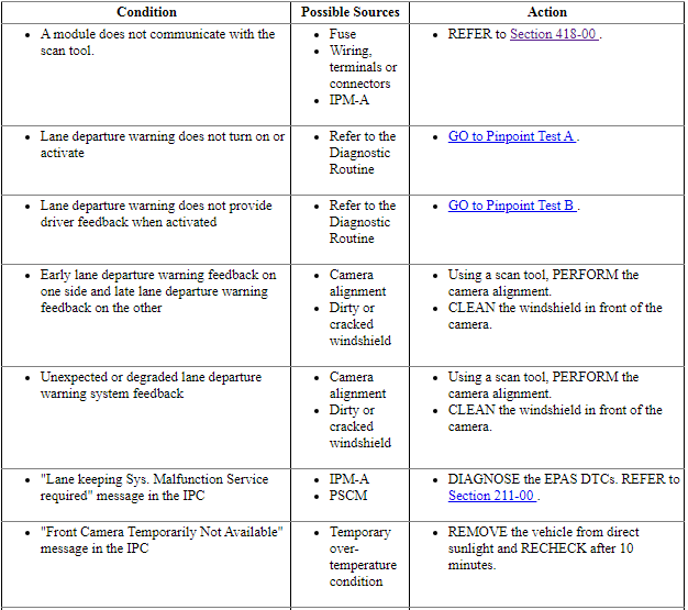
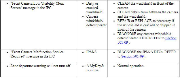
Symptom Chart
Diagnostics in this manual assume a certain skill level and knowledge of Ford-specific diagnostic practices. Refer to Diagnostic Methods in Section 100-00 for information about these practices.
Pinpoint Tests
Pinpoint Test A: Lane Departure Warning (LDW) Does Not Turn On Or Activate
Diagnostic Overview
Diagnostics in this manual assume a certain skill level and knowledge of Ford-specific diagnostic practices. Refer to Diagnostic Methods in Section 100-00 for information about these practices.
Refer to Wiring Diagrams Cell 124 for schematic and connector information.
Normal Operation and Fault Conditions
Refer to Lane Departure Warning (LDW) in Lane Departure Warning.
IPM-A DTC Fault Trigger Conditions
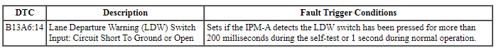
-
Possible Sources
- Fuse
- Wiring, terminals or connectors
- LDW switch
- IPM-A
- PSCM
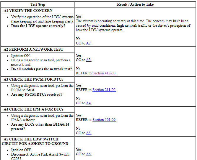
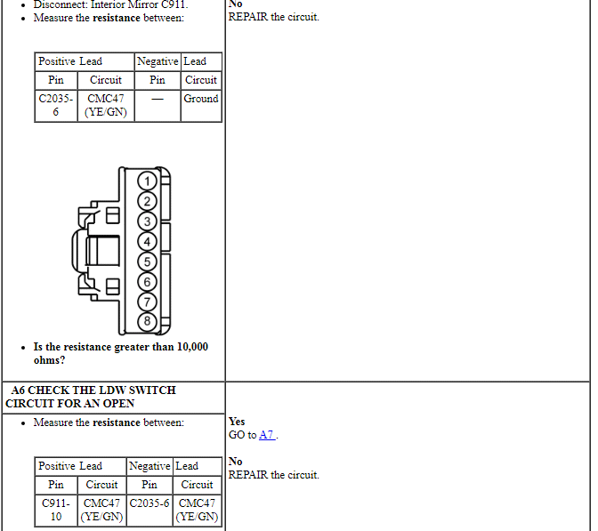
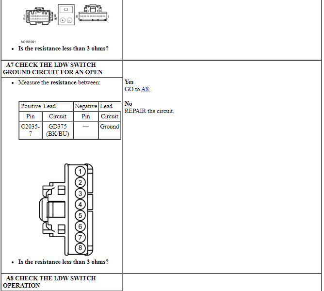
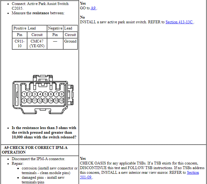
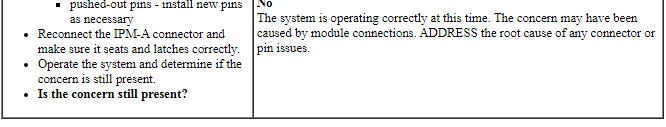
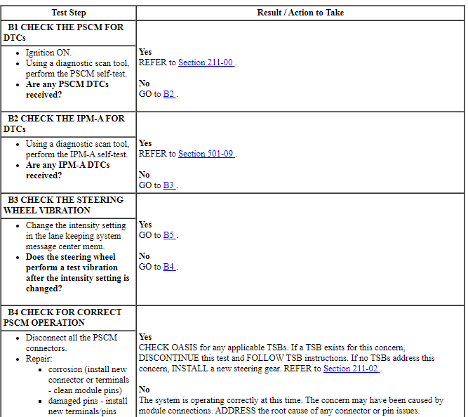
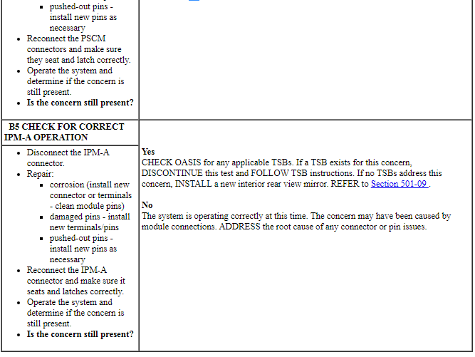
PINPOINT TEST A: LANE DEPARTURE WARNING (LDW) DOES NOT TURN ON OR ACTIVATE
Pinpoint Test B: Lane Departure Warning (LDW) Does Not Provide Driver Feedback When Activated
Diagnostic Overview
Diagnostics in this manual assume a certain skill level and knowledge of Ford-specific diagnostic practices. Refer to Diagnostic Methods in Section 100-00 for information about these practices.
Refer to Wiring Diagrams Cell 124 for schematic and connector information.
Normal Operation and Fault Conditions
The LDW only provides feedback when the system is on, the vehicle speed is above 64 km/h (40 mph) and the IPM-A detects lane markings on at least one side of the vehicle. Refer to Lane Departure Warning.
-
Possible Sources
- Fuse
- Wiring, terminals or connectors
- IPM-A
- PSCM
Visual Inspection and Diagnostic Pre-checks
Verify that the LDW system turns on and the lane indicators turn green when the system is active. If the LDW system turns on but the lines do not turn green, GO to Pinpoint Test A.
PINPOINT TEST B: LANE DEPARTURE WARNING (LDW) DOES NOT PROVIDE DRIVER FEEDBACK WHEN ACTIVATED
 Side And Rear Vision
DESCRIPTION AND OPERATION
Blind Spot Monitoring
Component Location
Exterior rear view mirror
SOD-R and SOD-L
Overview
BLIS is a vehicle feature that aids the driver in assessing whe ...
 Multifunction Electronic Modules
SPECIFICATIONS
Torque Specifications
DESCRIPTION AND OPERATION
Module Controlled Functions
Component Location
Multifunction Electronic Modules
BCM
RFA module
Overview
The BCM contr ...
Other materials:
Module Configuration
DESCRIPTION AND OPERATION
Module Configuration
System Operation
Programmable Module Installation (PMI)
Programmable Module Installation (PMI) is a scan tool process which
configures settings in a new module. Data used for the PMI process is
automatically downloaded from the original modu ...
Body Closures
SPECIFICATIONS
Torque Specifications
GENERAL PROCEDURES
Door Adjustment - Front
Loosen the front door hinge-to-front door bolts until the front door is
able to move slightly.
Align the front door.
Align the front door body angles to the rear door.
Be sure that the front door is flush ...
Anti-Theft - Passive Anti-Theft System (PATS), With Intelligent Access (IA)
DESCRIPTION AND OPERATION
Anti-Theft
Component Location
RFA Module
Backup Transceiver
TPM Module
Passive Start Antenna (3 required)
Overview
PATS deters the vehicle from theft by preventing the ignition from turning on
and the engine from starting unless a programmed IA&n ...
