SPECIFICATIONS
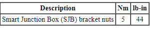
Torque Specifications
DESCRIPTION AND OPERATION
Module Controlled Functions
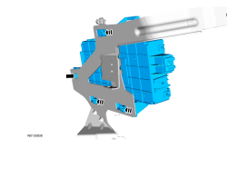
Component Location
Multifunction Electronic Modules
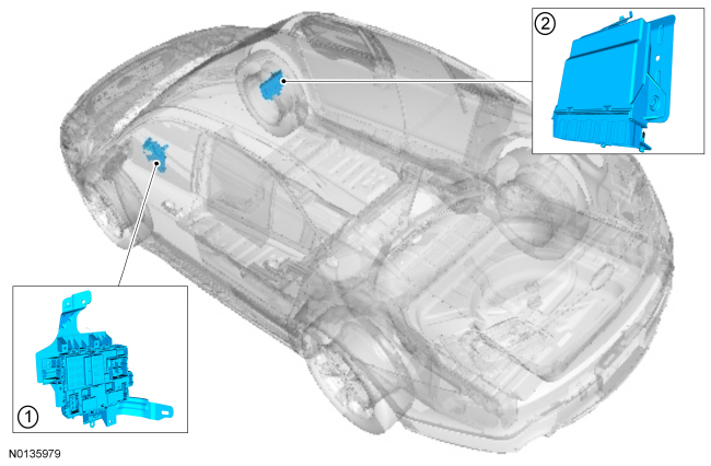
- BCM
- RFA module
Overview
The BCM controls the following:
- Battery saver function
- Brake shift interlock
- Delayed accessory function
- Dimmable backlighting
- Exterior lighting
- Horn
- Ignition state messaging
- Interior lighting
- Keyless entry keypad (without IA )
- Decklid release (without IA )
- PATS (vehicles without IA )
- Perimeter alarm
- Power door locks (vehicles without IA )
- Post crash alert function
- RKE system (without IA )
- Remote start
- TPMS
The RFA module (with IA only) controls the following:
- IA function
- Key validation (part of the PATS )
- Keyless entry keypad
- Decklid release
- PATS
- Power door locks
System Operation
Battery Saver
NOTE: The battery saver time-out is 1 minute if the vehicle has less than 201 km (125 mi).
NOTE: The battery saver does not control the parking lamps if the headlamp switch is in the PARKING LAMPS ON position.
To save battery voltage, the BCM provides automatic shut-off of the interior and exterior lamps after a time-out period when the ignition is off. The BCM monitors the ignition state and input from the RKE system to determine when to energize or de-energize the battery saver relay and to shut the power off to the lamps. A timer in the BCM starts when:
- the ignition changes to OFF,
- any door or decklid becomes ajar while the ignition is off,
- an UNLOCK button of the RKE transmitter is pressed while the ignition is off,
- a valid keypad code is entered while the ignition is off,
- or the courtesy lamp switch (integrated into the main light switch) is used to turn the courtesy lamps on while the ignition is off.
When 10 minutes have elapsed, the BCM automatically shuts off voltage to the lamps. The timer restarts (voltage is restored if the BCM is in battery saver mode) if:
- the ignition transitions out of OFF,
- any door or decklid becomes ajar,
- the UNLOCK button of the RKE transmitter is pressed,
- a valid keypad code is entered,
- the courtesy lamp switch is pressed.
Post Crash Alert Function
The post crash alert is a function controlled by the BCM. If the RCM determines an impact of enough severity (the air bags may or may not be deployed), the post crash alert function activates. The post crash alert function activates the hazard lamp function and cycles the horn on 3 times, then off for 4 seconds, and repeats this cycle until the battery is discharged or the function is turned off. The post crash alert function can be turned off by:
- pressing the hazard flasher lamp switch (which may need to be pressed twice).
- pressing the RKE transmitter UNLOCK button.
- pressing the RKE transmitter PANIC button.
FET Protection
A FET is a type of transistor that, when used with module software, monitors and controls current flow on module outputs. The FET protection strategy prevents module damage in the event of excessive current flow.
The BCM utilizes a FET protective circuit strategy for many of its outputs (for example, a headlamp output circuit). Output loads (current level) are monitored for excessive current (typically short circuits) and are shut down (turns off the voltage or ground provided by the module) when a fault event is detected. A short circuit DTC is stored at the fault event and a cumulative counter is started.
When the demand for the output is no longer present, the module resets the FET circuit protection to allow the circuit to function. The next time the driver requests a circuit to activate that has been shut down by a previous short ( FET protection) and the circuit is still shorted, the FET protection shuts off the circuit again and the cumulative counter advances.
When the excessive circuit load occurs often enough, the module shuts down the output until a repair procedure is carried out. Each FET protected circuit has 3 predefined levels of short circuit tolerance based on the harmful effect of each circuit fault on the FET and the ability of the FET to withstand it. A module lifetime level of fault events is established based upon the durability of the FET. If the total tolerance level is determined to be 600 fault events, the 3 predefined levels would be 200, 400 and 600 fault events.
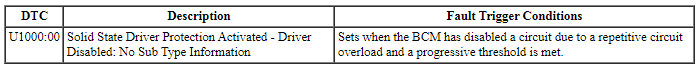
When each tolerance level is reached, DTC U1000:00 should set along with the short circuit DTC that was stored on the first failure. These DTCs cannot be cleared until the vehicle is repaired.
After the repair, it is necessary to clear the DTCs using the Clear DTC operation on the scan tool, cycling the ignition, and run the BCM on-demand self-test.
The module never resets the fault event counter to zero and continues to advance the fault event counter as short circuit fault events occur. If the number of short circuit fault events reach the third level, DTC U3000:49 sets along with the associated short circuit DTC. DTC U3000:49 cannot be cleared and the module must be replaced after the initial fault is repaired.
Gateway Function
The BCM acts as a gateway module by receiving information in one format and transmitting it to other modules using another format. For example, the BCM receives the vehicle speed data from the PCM over the, HS-CAN the BCM converts the data into a MS-CAN message and sends (gateways) the message to other network modules such as the HVAC module. This enables network communication between modules that do not communicate using the same network ( HS-CAN or MS-CAN ).
Component Description
Body Control Module (BCM)
The BCM is a multifunction module that requires a PMI when replaced. Refer to Section 418-01.
Remote Function Actuator (RFA) Module
The RFA module is a multifunction module that requires a PMI when replaced. Refer to Section 418-01.
DIAGNOSIS AND TESTING
Diagnostic Trouble Code (DTC) Chart
Each module has a comprehensive DTC chart listed in an appropriate section. Refer to the table below for the section reference of a specific module DTC chart.
Body Control Module (BCM)
DTC Chart
Diagnostics in this manual assume a certain skill level and knowledge of Ford-specific diagnostic practices. Refer to Diagnostic Methods in Section 100-00 for information about these practices.
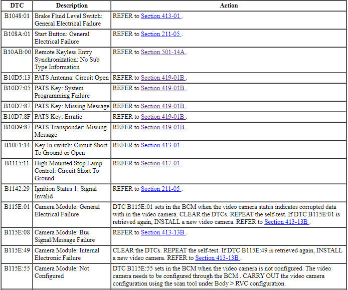
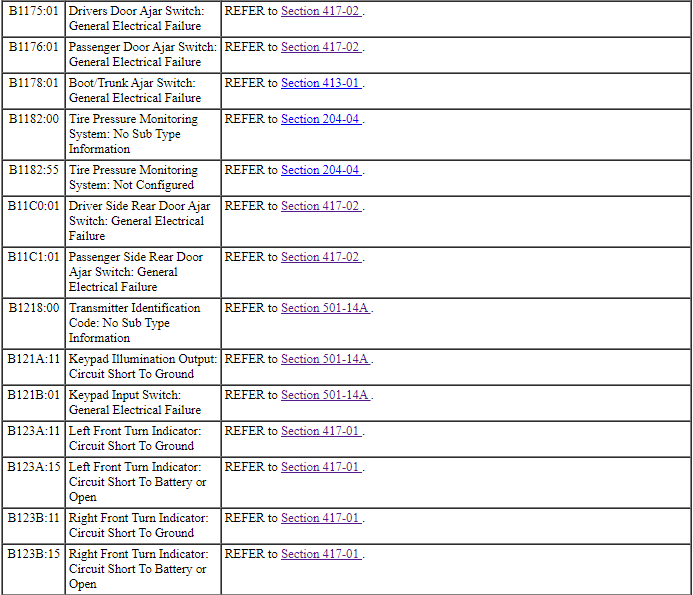
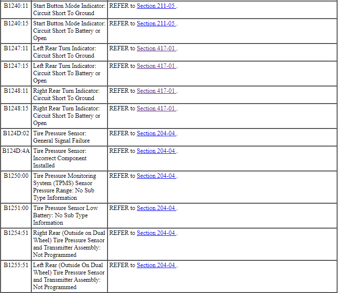
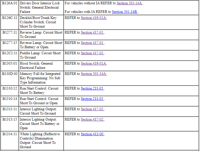
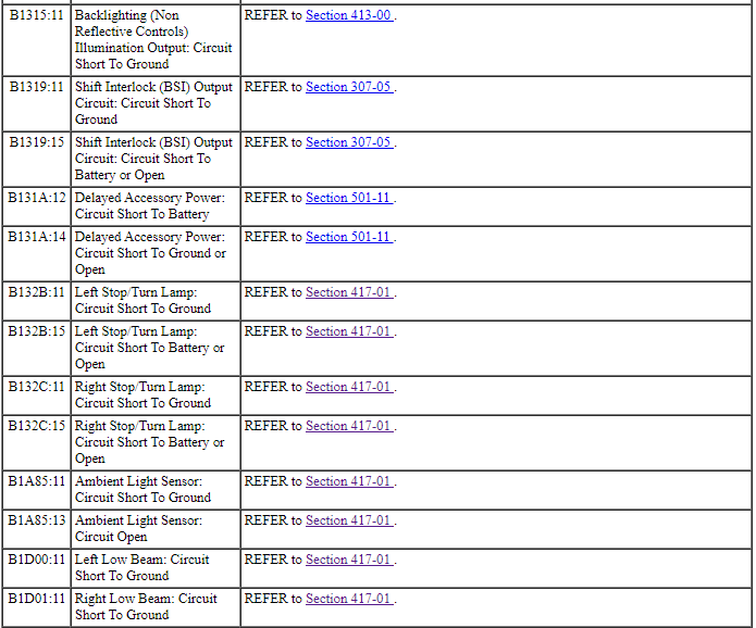
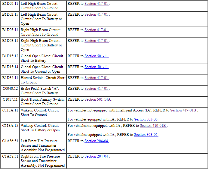
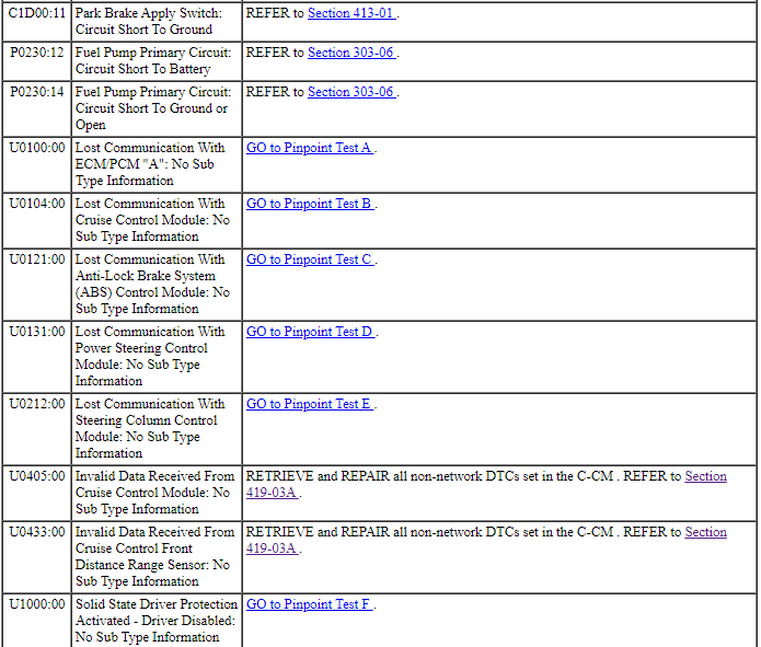
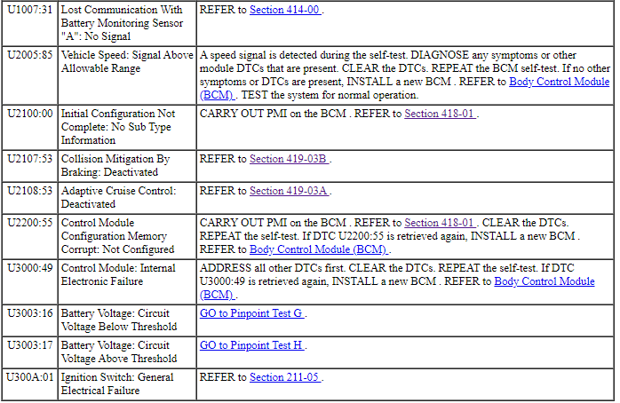
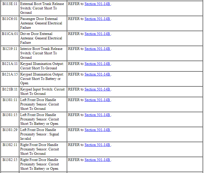
BCM DTC Chart
Symptom Chart
Diagnostics in this manual assume a certain skill level and knowledge of Ford-specific diagnostic practices. Refer to Diagnostic Methods in Section 100-00 for information about these practices.
Pinpoint Tests
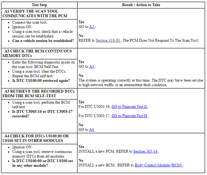
Pinpoint Test A: DTC U0100:00
Diagnostic Overview
Diagnostics in this manual assume a certain skill level and knowledge of Ford-specific diagnostic practices. Refer to Diagnostic Methods in Section 100-00 for information about these practices.
DTC Fault Trigger Conditions
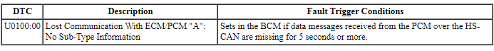
-
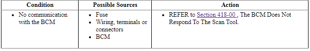
Possible Sources
- BCM
- PCM
PINPOINT TEST A: DTC U0100:00
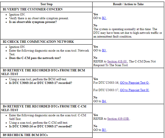
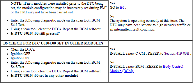
Pinpoint Test B: DTC U0104:00
Diagnostic Overview
Diagnostics in this manual assume a certain skill level and knowledge of Ford-specific diagnostic practices. Refer to Diagnostic Methods in Section 100-00 for information about these practices.
DTC Fault Trigger Conditions
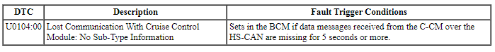
-
Possible Sources
- BCM
- C-CM
PINPOINT TEST B: DTC U0104:00
Pinpoint Test C: DTC U0121:00
Diagnostic Overview
Diagnostics in this manual assume a certain skill level and knowledge of Ford-specific diagnostic practices. Refer to Diagnostic Methods in Section 100-00 for information about these practices.
DTC Fault Trigger Conditions
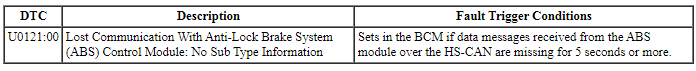
-
Possible Sources
- ABS module
- BCM
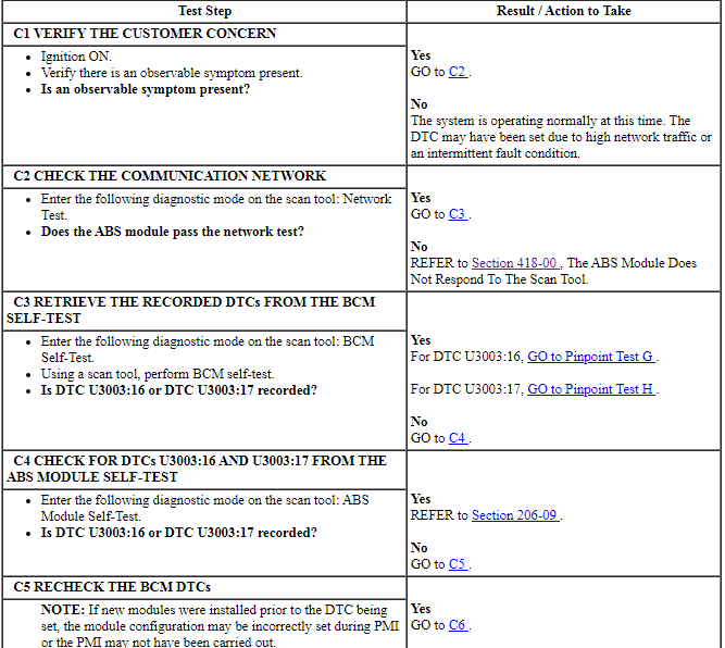
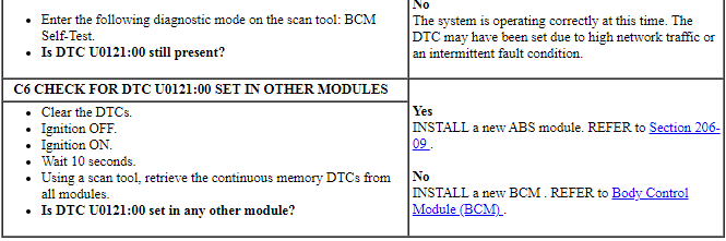
PINPOINT TEST C: DTC U0121:00
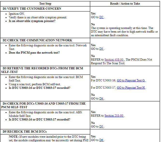
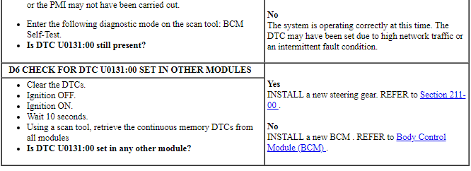
Pinpoint Test D: DTC U0131:00
Diagnostic Overview
Diagnostics in this manual assume a certain skill level and knowledge of Ford-specific diagnostic practices. Refer to Diagnostic Methods in Section 100-00 for information about these practices.
DTC Fault Trigger Conditions

-
Possible Sources
- BCM
- PSCM
PINPOINT TEST D: DTC U0131:00
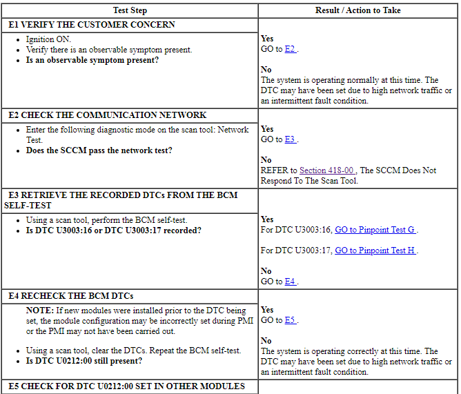
Pinpoint Test E: DTC U0212:00
Diagnostic Overview
Diagnostics in this manual assume a certain skill level and knowledge of Ford-specific diagnostic practices. Refer to Diagnostic Methods in Section 100-00 for information about these practices.
DTC Fault Trigger Conditions
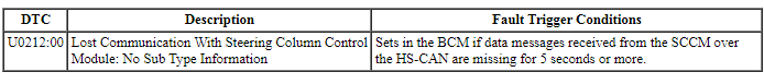
-
Possible Sources
- BCM
- SCCM
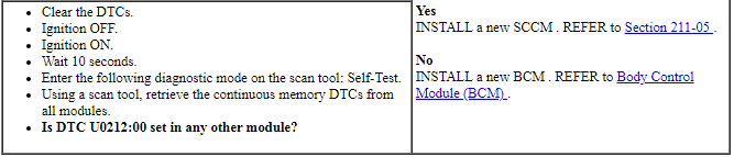
PINPOINT TEST E: DTC U0212:00
Pinpoint Test F: DTC U1000:00
Diagnostic Overview
Diagnostics in this manual assume a certain skill level and knowledge of Ford-specific diagnostic practices. Refer to Diagnostic Methods in Section 100-00 for information about these practices.
Normal Operation and Fault Conditions
The BCM controls the output of several vehicle systems using solid state drivers. When an overload occurs on any of these drivers, a DTC sets. The module also tracks the number of repetitive faults on each of these circuits. The module compares this number of overloads to 3 progressive thresholds established for each circuit. At each threshold, DTC U1000:00 sets along with the DTC associated with the affected circuit.
DTC Fault Trigger Conditions
-
Possible Sources
- BCM
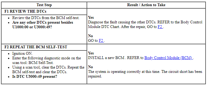
PINPOINT TEST F: DTC U1000:00
Pinpoint Test G: DTC U3003:16
Diagnostic Overview
Diagnostics in this manual assume a certain skill level and knowledge of Ford-specific diagnostic practices. Refer to Diagnostic Methods in Section 100-00 for information about these practices.
Refer to Wiring Diagrams Cell 10, Grounds for schematic and connector information.
Refer to Wiring Diagrams Cell 13, Power Distribution/BCM for schematic and connector information.
DTC Fault Trigger Conditions
-
Possible Sources
- Wiring, terminals or connectors
- Battery
- Generator
- PCM
- RFA module
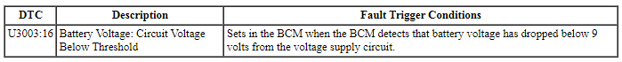
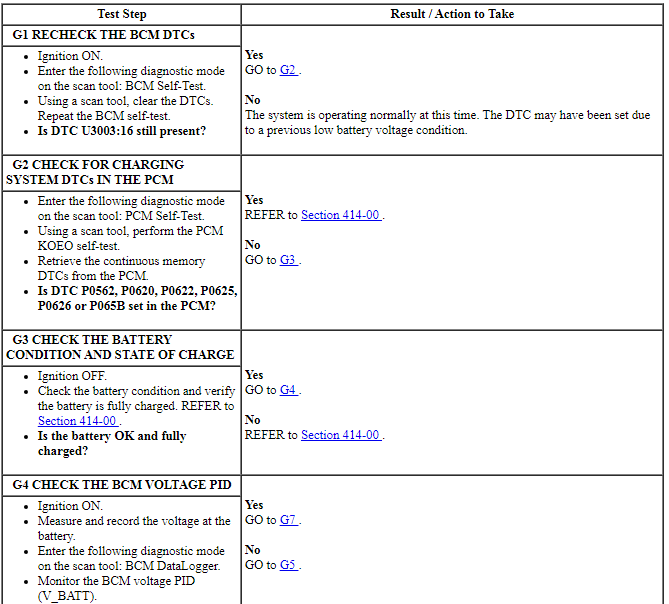
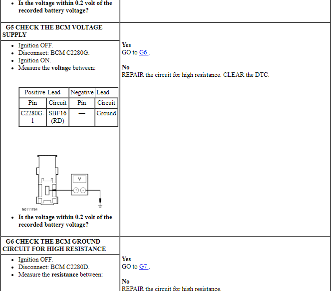
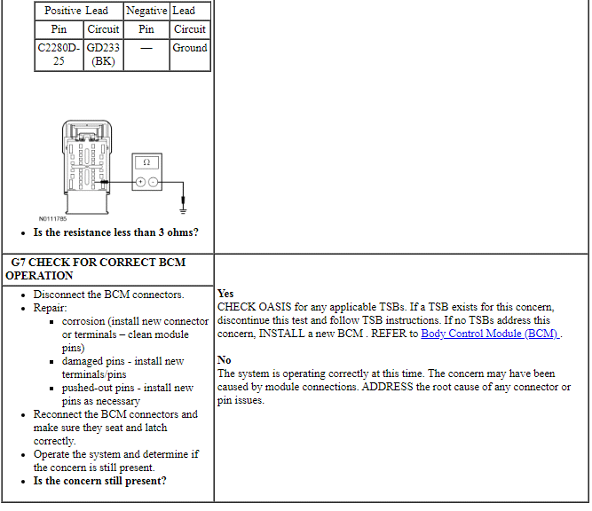
PINPOINT TEST G: DTC U3003:16
Pinpoint Test H: DTC U3003:17
Diagnostic Overview
Diagnostics in this manual assume a certain skill level and knowledge of Ford-specific diagnostic practices. Refer to Diagnostic Methods in Section 100-00 for information about these practices.
DTC Fault Trigger Conditions

-
Possible Sources
- Wiring, terminals or connectors
- Battery
- Generator
- PCM
- BCM
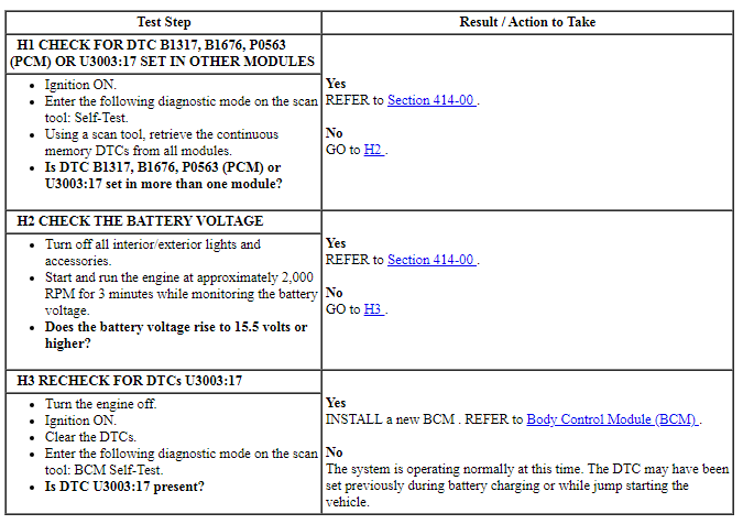
PINPOINT TEST H: DTC U3003:17
Remote Function Actuator (RFA) Module
DTC Charts
Diagnostics in this manual assume a certain skill level and knowledge of Ford-specific diagnostic practices. Refer to Diagnostic Methods in Section 100-00 for information about these practices.
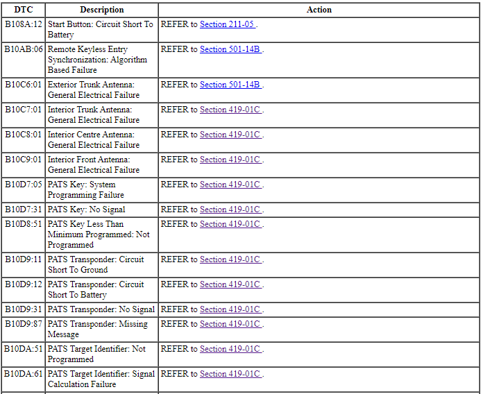
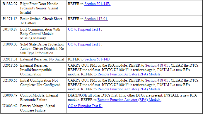
Remote Function Actuator (RFA) Module DTC Chart
NOTE: Refer to Description and Operation, Intelligent Access (IA) with Push Button Start in Section 419-01C to review the procedures for achieving the various ignition states (ignition off, ignition in accessory, ignition on, ignition start) on vehicles with this feature.
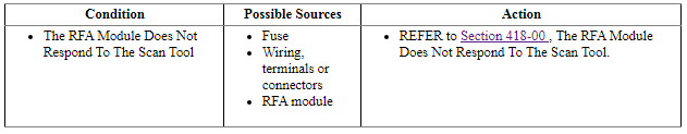
Symptom Chart
Diagnostics in this manual assume a certain skill level and knowledge of Ford-specific diagnostic practices. Refer to Diagnostic Methods in Section 100-00 for information about these practices.
NOTE: Refer to Description and Operation, Intelligent Access (IA) with Push Button Start in Section 419-01B to review the procedures for achieving the various ignition states (ignition off, ignition in accessory, ignition on, ignition start) on vehicles with this feature.
Pinpoint Tests
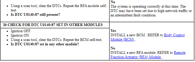
Pinpoint Test I: DTC U0140:87
Diagnostic Overview
Diagnostics in this manual assume a certain skill level and knowledge of Ford-specific diagnostic practices. Refer to Diagnostic Methods in Section 100-00 for information about these practices.
Normal Operation and Fault Conditions
DTC Fault Trigger Conditions

-
Possible Sources
- BCM
- RFA Module
PINPOINT TEST I: DTC U0140:87
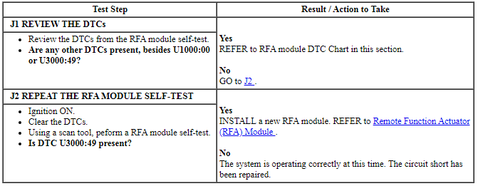
Pinpoint Test J: DTC U1000:00
Diagnostic Overview
Diagnostics in this manual assume a certain skill level and knowledge of Ford-specific diagnostic practices. Refer to Diagnostic Methods in Section 100-00 for information about these practices.
DTC Fault Trigger Conditions

-
Possible Sources
- RFA module
PINPOINT TEST J: DTC U1000:00
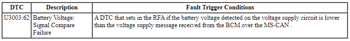
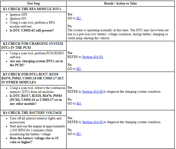
Pinpoint Test K: DTC U3003:62
Diagnostic Overview
Diagnostics in this manual assume a certain skill level and knowledge of Ford-specific diagnostic practices. Refer to Diagnostic Methods in Section 100-00 for information about these practices.
Refer to Wiring Diagrams Cell 10, Grounds for schematic and connector information.
Refer to Wiring Diagrams Cell 13, Power Distribution/BCM for schematic and connector information.
DTC Fault Trigger Conditions
-
Possible Sources
- Wiring, terminals or connectors
- Battery
- Generator
- PCM
- RFA module
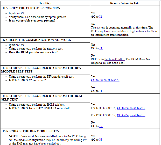
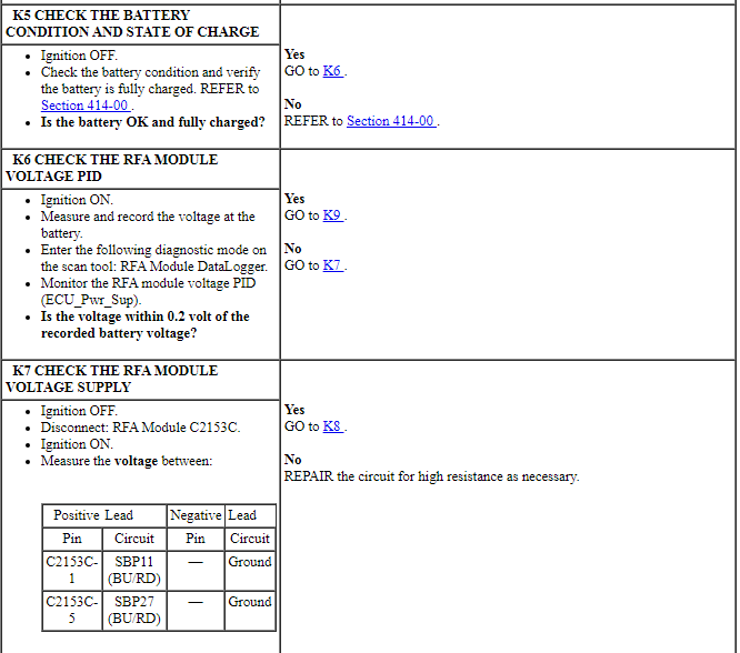
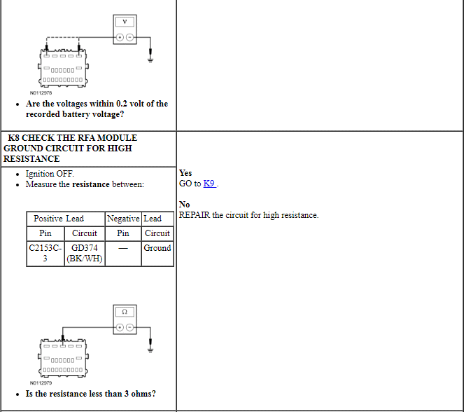
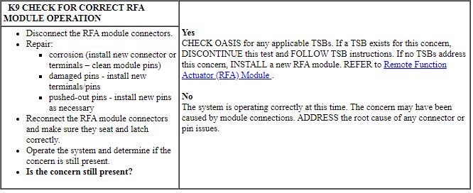
PINPOINT TEST K: DTC U3003:62
GENERAL PROCEDURES
Disabling Transport or Factory Mode
Transport Mode
NOTE: During vehicle build, some vehicle modules (Instrument Panel Cluster (IPC), Body Control Module (BCM) and Remote Functions Receiver (RFR) module [if equipped] ) are set in factory mode. While in the factory mode, the IPC displays FACTORY MODE CONTACT DEALER in the message center. If the vehicle is set in factory mode, the system does not automatically revert to another mode and must be manually set to either the transport or normal operation mode. When the vehicle build is complete, the vehicle is set to transport mode. While in transport mode, the IPC displays TRANSPORT MODE CONTACT DEALER in the message center. Transport mode is used to reduce the drain on the battery during longer periods where the vehicle is not used. Various systems may be altered or are disabled when in the transport mode. The vehicle automatically reverts to normal operation mode after being driven 201 km (125 mi).
- Verify the battery is fully charged.
- To disable or turn off the transport mode, carry out (within 10
seconds):
- With ignition in RUN, press brake pedal 5 times.
- Press hazard switch 4 times (on, off, on, off).
Factory Mode
NOTE: During vehicle build, some vehicle modules ( IPC, BCM and Remote Functions Receiver (RFR) module [if equipped] ) are set in factory mode. While in the factory mode, the IPC displays FACTORY MODE CONTACT DEALER in the message center. If the vehicle is set in factory mode, the system automatically reverts back to normal mode after 60 ignition cycles.
- Verify the battery is fully charged.
- Cycle the ignition 60 times.
REMOVAL AND INSTALLATION
Body Control Module (BCM)
Removal
NOTICE: When any vehicle module is being programmed, connect an external battery charger to make sure that the module programming is completed without the interruption due to the load shedding feature becoming active. The external battery charger must maintain a system voltage above 13 volts. This can require a charger setting higher than the lowest charge setting. The external battery charger negative connection must be made to an engine or vehicle chassis ground and not the negative battery terminal. If the connection is to the negative battery terminal, load shedding cannot be prevented from being invoked and module programming may be corrupted. After charging has begun, start the engine to clear any load shed states and then turn the engine off and proceed with programming.
NOTE: If installing a new module, it is necessary to upload the module configuration information to the scan tool prior to removing the module. This information must be downloaded into the new module after installation.
NOTE: If installing a new BCM, all vehicle keys are erased during the parameter reset procedure. For vehicles without Intelligent Access (IA) verify at least 2 of the vehicle keys are available prior to carrying out this procedure.
- Connect a battery charger. Refer to Section 414-01.
- NOTE: This step is necessary only if the BCM is being replaced.
Upload the module configuration information from the BCM. Refer to Section 418-01.
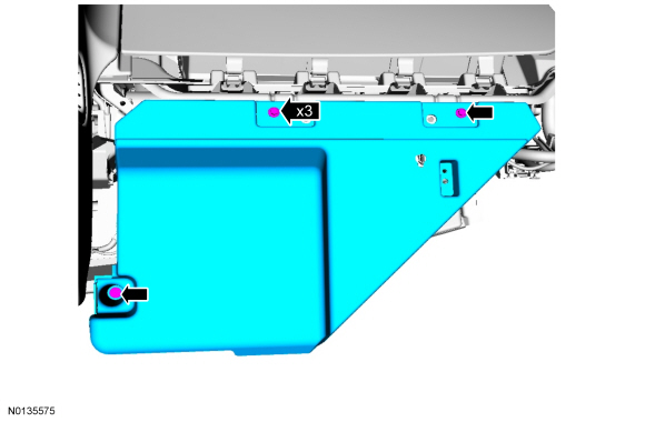
- Remove the steering column opening trim panel. Refer to Section 501-12.
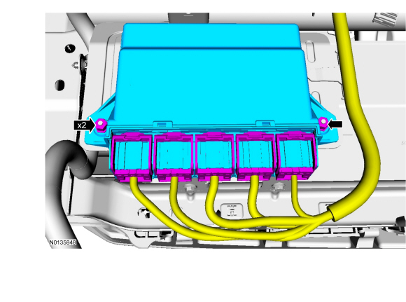
- Disconnect the 7 BCM electrical connectors and remove the 2 harness pushpins from the BCM.
- Lift the BCM release tab(s) (away from the BCM bracket), slide the BCM to the left and remove.
Installation
- Install the BCM and connect the electrical connectors.
- NOTE: If the BCM was not replaced, this is the last step that is
necessary.
Install the steering column opening trim panel.
- NOTE: If the ignition is left in RUN or ACC and the engine is OFF
during the vehicle battery charging process, the Battery Monitoring System
(BMS) can turn off the ignition causing the configuration to fail.
After battery charging is complete, carry out the BMS reset by following the scan tool on screen instructions.
- NOTE: Once the BCM Programmable Module Installation (PMI) is
complete, follow the scan tool on-screen instructions for performing the
Configurable Engine Immobilizer (CEI) lock configuration.
Download the BCM configuration information from the scan tool to the new BCM by following the scan tool on screen instructions.
- NOTE: If a new BCM is installed, the BCM and the PCM require a
parameter reset to allow the BCM and PCM to recognize each other.
If installing a new BCM, carry out the parameter reset procedure and program the keys. For vehicles without Intelligent Access (IA), refer to Section 419-01B. For vehicles with IA, refer to Section 419-01C.
- If equipped with IA, carry out the keyless entry keypad code reset. Refer to Keyless Entry Keypad Code Programming in Section 501-14B.
- Train the tire pressure sensors. Refer to Section 204-04.
- NOTE: If the dome lamps are flashing after BCM installation, it
was not configured completely. Repeat steps 3 through 7.
Carry out the BCM self-test to confirm all DTCs have been cleared.
Remote Function Actuator (RFA) Module
Removal
- NOTE: This step is only necessary if the Remote Function Actuator
(RFA) module is being replaced.
NOTE: Prior to the replacement of the module, it is necessary to upload the module configuration information to the scan tool. This information must be downloaded into the new module after installation. For additional information, refer to Section 418-01.
Upload the module configuration information from the RFA module by following the scan tool on screen instructions.
- Remove the RH side instrument panel hush panel.

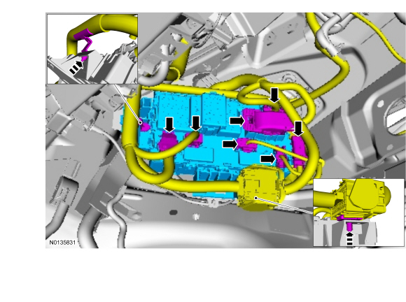
- Remove the 2 nuts and remove the RFA module.
- Disconnect the RFA module electrical connectors.

Installation
- Install the RFA module.
- Connect the RFA module electrical connectors.
- Tighten to 3 Nm (27 lb-in).
- Install the RH side instrument panel hush panel.
- Download the RFA module configuration information from the scan tool to the new RFA module by following the scan tool on screen instructions.
- Carry out the parameter reset between the RFA module and the Body Control Module (BCM). For additional information, refer to Passive Anti-Theft System (PATS) Parameter Reset in Section 419-01B.
- Program the Intelligent Access (IA) keys (minimum of 2) into the new RFA module. For additional information, refer to Key Programming Using Diagnostic Equipment in Section 419-01B.
- Turn the ignition ON.
- Carry out the keyless entry keypad code reset. For additional information, refer to Keyless Entry Keypad Code Programming in Section 501-14B.
- Carry out the RFA module self-test to confirm all DTCs have been cleared.
 Lane Departure Warning
DESCRIPTION AND OPERATION
Lane Departure Warning
Overview
The LDW is composed of the lane keeping alert and lane keeping aid functions.
The lane keeping alert detects unintentional drifting ...
 Body and Paint
...
Other materials:
Temporary mobility kit
Note: The temporary mobility kit sealant compound in the canister is
to
be used for one tire only. See your Ford authorized dealer for additional
replacement sealant canisters.
Your vehicle may be equipped with a temporary mobility kit (located in
the spare tire well in the trunk). The tempo ...
Transaxle/Transmission Cooling - 6F35
SPECIFICATIONS
Material
Torque Specifications
DESCRIPTION AND OPERATION
Transaxle Cooling
The transmission fluid cooling system consists of the following:
OTA transmission fluid cooler
Front transmission fluid cooler tube assembly
Rear transmission fluid cooler tube assembly
Transmission ...
Sun visors
Slide-On-Rod
Rotate the visor toward the side
window and extend it rearward for
extra sunlight coverage.
Retract the visor before moving it
back toward the windshield and
storing it.
Illuminated Visor Vanity Mirror
Lift the cover to switch on the
lamp. ...
