Frame Members
General Equipment

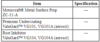
Material
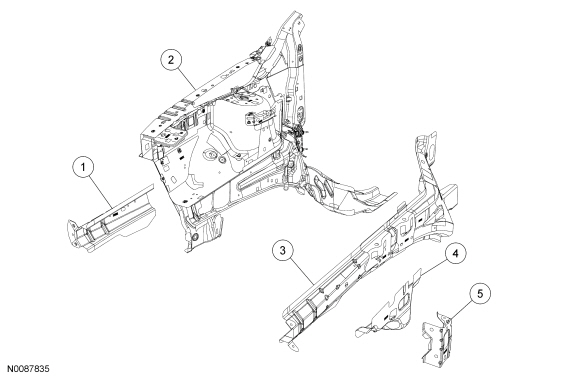
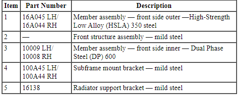
Front Side Members - Exploded View
NOTE: Right side shown, left side similar.
WARNING: Collision damage repair must conform to the instructions contained in this workshop manual. Replacement components must be new, genuine Ford Motor Company parts. Recycled, salvaged, aftermarket or reconditioned parts (including body parts, wheels or safety restraint components) are not authorized by Ford.
Departure from the instructions provided in this manual, including alternate repair methods or the use of substitute components, risks compromising crash safety. Failure to follow these instructions may adversely affect structural integrity and crash safety performance, which could result in serious personal injury to vehicle occupants in a crash.
WARNING: Invisible ultraviolet and infrared rays emitted in welding can injure unprotected eyes and skin. Always use protection such as a welder's helmet with dark-colored filter lenses of the correct density. Electric welding will produce intense radiation, therefore, filter plate lenses of the deepest shade providing adequate visibility are recommended. It is strongly recommended that persons working in the weld area wear flash safety goggles. Also wear protective clothing. Failure to follow these instructions may result in serious personal injury.
WARNING: Frame rail crush zones absorb crash energy during a collision and must be replaced if damaged. Prior to replacement of frame rail crush zones, straighten damaged frame rails to correct frame dimensions. Failure to follow these instructions may adversely affect frame rail crush zone performance and may result in serious personal injury to vehicle occupants in a crash.
WARNING: Always wear protective equipment including eye protection with side shields, and a dust mask when sanding or grinding. Failure to follow these instructions may result in serious personal injury.
NOTE: Observe prescribed welding procedures when carrying out any repair to unibody/frame structure. For additional information, refer to Welding Precautions - Steel in this section.
- Remove the hood.
- Position the vehicle on a frame repair rack following the manufacturer's
recommendations. Measure the vehicle to determine if the body requires
straightening and alignment. If necessary, rough pull the vehicle to restore
the vehicle to pre-accident dimensions. For additional dimensional
information, refer to Body in this section.
- Remove the front bumper.
- Remove the battery.
- Remove the fender(s) from the affected side(s).
- Remove the radiator.
- Remove the radiator bolster assembly.
- Remove the subframe, powertrain and drivetrain assemblies as required.
- Remove the suspension components as required.
- NOTE: Factory spot welds may be substituted with either
Squeeze-Type Resistance Spot Welding (STRW) welds or Metal Inert Gas (MIG)
plug welds. Spot/plug welds should equal factory welds in both location and
quantity. Do not place a new spot weld directly over an original weld
location. Plug weld hole should equal 8 mm (0.31 in) diameter.
Drill out the spot welds and remove the subframe mount bracket assembly from the affected side(s).
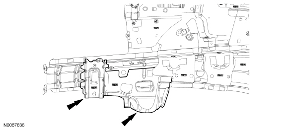
- NOTE: The following 3 steps illustrate the 3 cut-points that can
be used when carrying out repairs, depending on severity of collision
damage. Choose the appropriate cut-point as necessary.
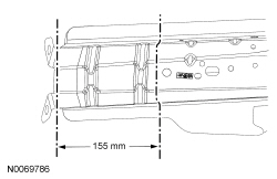
NOTE: Cut point No. 1. LH shown, RH similar.
Scribe a cut-line 155 mm (6.1 in) from the front bumper bracket on the outer frame rail. Using a plasma cutter, cut-off wheel or reciprocating saw, cut off the front rail inner and outer assemblies along the scribe line.- Scribe a cut-line 40 mm (1.57 in) to 50 mm (1.96 in) rearward of the initial frame rail cut, on the outer portion of the rail assembly. Using a cut-off wheel or equivalent, cut and remove that portion of outer rail only, this will create an overlap joint.
- Dress the weld surfaces.
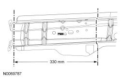
- NOTE: Cut point No. 2. LH shown, RH similar.
Scribe a cut-line 330 mm (12.99 in) from the front bumper bracket on the outer frame rail. Using a plasma cutter, cut-off wheel or reciprocating saw, cut off the front rail inner and outer assemblies along the scribe line.
- Scribe a cut-line 40 mm (1.57 in) to 50 mm (1.96 in) rearward of the initial frame rail cut, on the outer portion of the rail assembly. Using a cut-off wheel or equivalent, cut and remove that portion of outer rail only, this will create an overlap joint.
- Dress the weld surfaces.
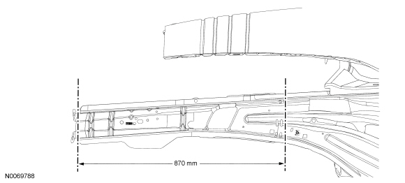
- NOTE: Cut point No. 3. LH shown, RH similar.
Scribe a cut-line 870 mm (34.25 in) from the front bumper bracket on the outer frame rail. Using a plasma cutter, cut-off wheel or reciprocating saw, cut off the front rail inner and outer assemblies along the scribe line.
- Scribe a cut-line 40 mm (1.57 in) to 50 mm (1.96 in) rearward of the initial frame rail cut, on the outer portion of the rail assembly. Using a cut-off wheel or equivalent, cut and remove that portion of outer rail only, this will create an overlap joint.
- Dress the weld surfaces.
- Chamfer the inner and outer rail cut line surfaces to improve butt weld condition.
- Transcribe the rail inner and outer cut-line to the new front rail inner and outer rail(s).
- Using a plasma cutter, cut-off wheel or reciprocating saw, cut to length. Chamfer the surface ends to improve weld surface.
- Using a wire brush or sandpaper, remove the E-coat from the outer
surfaces of the replacement service section within approximately 15 mm (0.59
in) of the repair joint.
- Using a wire brush, remove any foreign material from the frame within approximately 15 mm (0.59 in) of the repair joint. Prepare all bare metal surfaces with metal surface prep and a weld-through primer.
- Install and clamp the service replacement inner frame rail in place. Tack weld and verify correct alignment of the frame rail.
- Seam weld along the inside of the section joint using a MIG welder and
ER70S-3 wire 0.9 mm (0.035 in) to 0.11 mm (0.045 in) diameter.
- Verify correct alignment and underbody dimensions.
- Use a dye penetrant to determine if any cracks or large voids exist in
the weld joint. If cracks or other defects exist, grind out the defect and
repair until the weld is free of defects.
- Clean the repair area with metal surface prep and apply corrosion protection to the affected area.
- Clean the service replacement outer frame rail and apply anti-corrosion protection.
- Install and clamp the service replacement outer frame rail in place.
- Verify correct alignment of the outer frame rail.
- Seam weld along the section joint of the outer frame rail using a MIG welder and ER70S-3 wire 0.9 mm (0.035 in) to 1.1 mm (0.045 in) diameter.
- Use a dye penetrant to determine if any cracks or large voids exist in
the weld joint. If cracks or other defects exist, grind out the defect and
repair until the weld is free of defects.
- Clean the repair area with metal surface prep and apply corrosion protection to the affected area.
- NOTE: Factory spot welds may be substituted with
either STRW welds or MIG plug welds. Spot/plug welds should equal factory
welds in both location and quantity. Do not place a new spot weld directly
over an original weld location. Plug weld hole should equal 8 mm (0.31 in)
diameter.
Using a MIG welder or resistance spot welder, plug or spot weld along the top and bottom seam of the service replacement rails.
- Install the subframe mount bracket assembly if previously removed.
- Dress the welds as necessary and apply anti-corrosion protection.
- Reinstall the subframe and powertrain components if removed during
disassembly. For additional information, refer to Section 502-00,
and Section 307-01A.
- Add 2 additional spot welds for the subframe attachment bracket assembly and install weld nut W711013-S300 (left side sub-assembly only). Apply corrosion protection to the affected areas of the frame and service replacement section.
- Reinstall the radiator bolster assembly. For additional information, refer to Section 501-02.
- Reinstall the radiator. For additional information, refer to Section 303-03.
- Reinstall the battery. For additional information, refer to Section 414-01.
- Reinstall the fender(s). For additional information, refer to Section 501-02.
- Reinstall the front bumper. For additional information, refer to Section 501-19.
- Reinstall the hood.
Roof Panel
General Equipment

Material

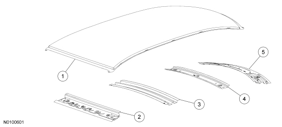
Roof Panel - Exploded View
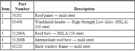
Removal
WARNING: Collision damage repair must conform to the instructions contained in this workshop manual. Replacement components must be new, genuine Ford Motor Company parts. Recycled, salvaged, aftermarket or reconditioned parts (including body parts, wheels or safety restraint components) are not authorized by Ford.
Departure from the instructions provided in this manual, including alternate repair methods or the use of substitute components, risks compromising crash safety. Failure to follow these instructions may adversely affect structural integrity and crash safety performance, which could result in serious personal injury to vehicle occupants in a crash.
WARNING: Invisible ultraviolet and infrared rays emitted in welding can injure unprotected eyes and skin. Always use protection such as a welder's helmet with dark-colored filter lenses of the correct density. Electric welding will produce intense radiation, therefore, filter plate lenses of the deepest shade providing adequate visibility are recommended. It is strongly recommended that persons working in the weld area wear flash safety goggles. Also wear protective clothing. Failure to follow these instructions may result in serious personal injury.
WARNING: Always wear protective equipment including eye protection with side shields, and a dust mask when sanding or grinding. Failure to follow these instructions may result in serious personal injury.
WARNING: Always refer to Material Safety Data Sheet (MSDS) when handling chemicals and wear protective equipment as directed. Examples may include but are not limited to respirators and chemically resistant gloves. Failure to follow these instructions may result in serious personal injury.
NOTICE: Be sure to adequately protect all glass, exterior finish and interior trim to avoid surface contamination from repair materials.
NOTE: The driver and passenger sides of the roof panel are laser skip-welded. Installation of a new roof panel will employ a weld-bonding technique. The use of mechanical welding and chemical bonding are both part of the installation technique.
- Remove the windshield and rear window glass. For additional information, refer to Section 501-11.
- Remove the headliner. For additional information, refer to Section 501-05.
- Remove the luggage rack (if equipped).
- Remove the roof ditch mouldings. For additional information, refer to Section 501-08.
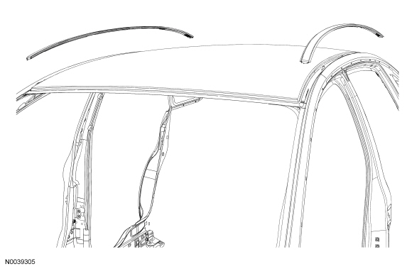
- From inside the vehicle, leaving as much of the foam as possible intact, separate the NVH foam along the roof bows from the roof panel using a flexible and sharp broad scraper or knife.
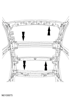
- Remove (drill out) all the roof panel spot welds from the windshield and rear window glass openings.
- Using an air hammer equipped with a panel cutter bit, carefully separate the panel from the vehicle by cutting the entire length along the inner portion of the roof ditch seam on each side of the roof panel.
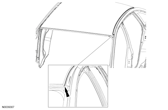
- With the help of an assistant, remove the roof panel from the vehicle.
- Using an air hammer equipped with a flat chisel, remove the remaining portion of the roof panel from the roof ditch area.
Installation
NOTICE: To avoid inadvertent damage, be sure to adequately protect all glass, exterior finish and interior trim.
- Using a hammer and dolly, straighten any damage caused to flange areas during removal.
- Using a grinder, carefully prepare the roof ditch area for the new roof panel.
- With the help of an assistant, position the new roof panel on the vehicle.
- Correctly align and index-mark the positioning of the panel-to-vehicle and remove the panel.
- Apply a bead of metal bonding adhesive along the flange of the roof ditch area on each side following label instructions.
- Apply a 13 mm (0.51 in) tall bead of seam sealer directly to the NVH foam remaining on the roof bows and immediately reinstall the roof panel aligning it to the index marks made during the test fitting.
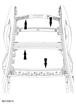
- NOTE: Do not lift the roof panel to reposition, slide it to
maintain contact with the sealer and adhesive.
Make sure good contact is made with the sealer and adhesive. Carefully clamp the roof panel on all sides.
- Using the resistance spot welder, weld the roof panel to the vehicle in the windshield and rear window glass areas. Spot welds should match factory welds in both location and quantity. Do not place a new spot weld directly over an original weld location. Plug weld hole should equal 8 mm (0.31 in) diameter.
- Using the Metal Inert Gas (MIG) welder, seam weld the roof panel sides with 10 mm (0.39 in) long weld beads spaced 40 mm (1.57 in) apart. Each corner must have a 10 mm (0.39 in) weld bead applied.
- Prepare the repair area for refinish material application following Ford-approved paint recommendations.
- Apply a quality primer-sealer following the paint manufacturer's recommendation for both compatibility and application.
- NOTE: Always use refinishing materials from a single paint
manufacturer. Combining products from more than one manufacturer may result
in refinishing material incompatibility issues and potential void of
warranty for each product applied.
If required, follow up with a quality primer-surfacer following Ford-approved paint recommendations. Block sand to level using the recommended grit sandpaper.
- Refinish the roof and repair area following Ford-approved paint recommendations.
- Allow refinishing materials sufficient cure time to permit safe handling (refer to paint manufacturer's specification) and install the roof ditch molding.
- Install the luggage rack (if equipped).
- Install the headliner. For additional information, refer to Section 501-05.
- Install the windshield and rear window glass. For additional information, refer to Section 501-11.
Inner Body Reinforcing Panels
General Equipment

Material
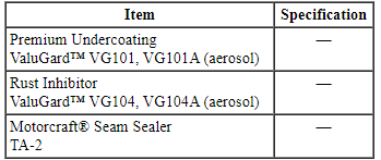
Inner Body Side
NOTICE: Sectioning procedures can only carried out on the outer body side panel. No sectioning repairs can be carried out on inner reinforcement panels. Failure to follow these instructions may compromise the structural integrity of the vehicle.
NOTE: Refer to the Ford Recommended Steel Repairability Matrix chart in the Specifications portion of this section for specific information regarding steel descriptions.
NOTE: Outer panels removed for clarity.
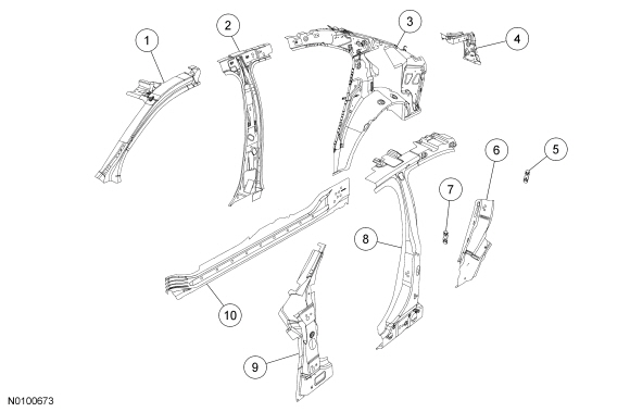
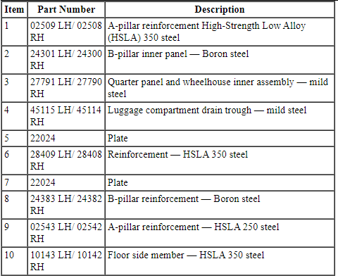
Front Structure
NOTE: Left side shown, right side similar.
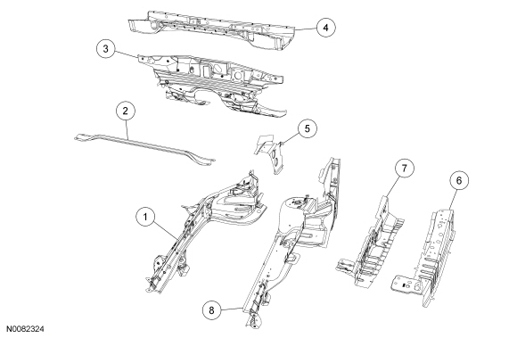
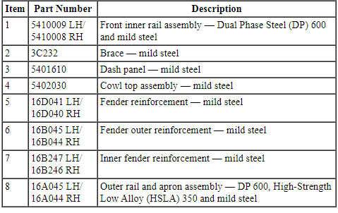
Underbody - Front
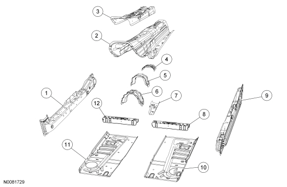
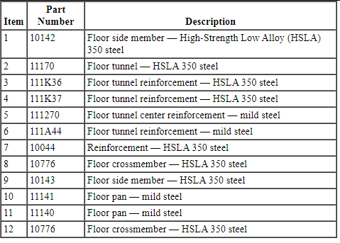
Underbody - Rear
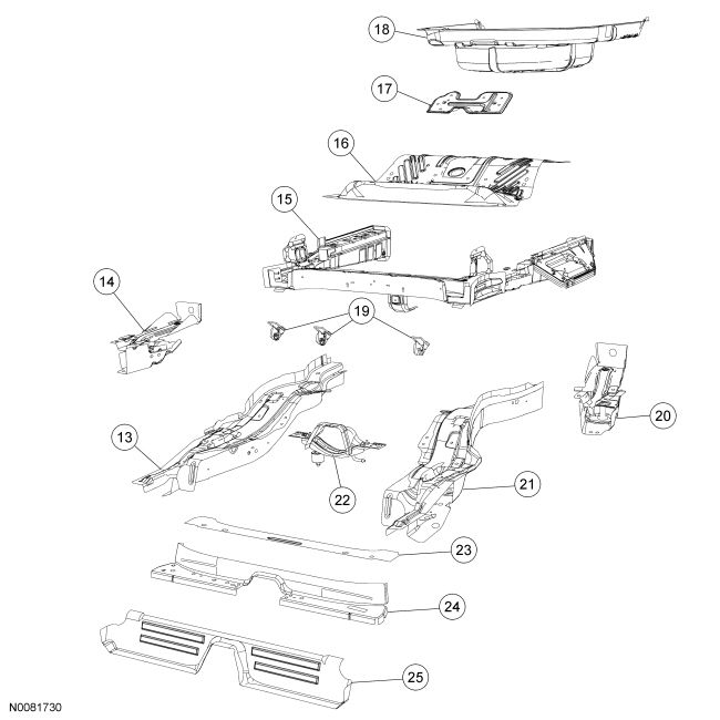
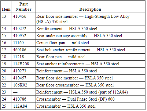
WARNING: Collision damage repair must conform to the instructions contained in this workshop manual. Replacement components must be new, genuine Ford Motor Company parts. Recycled, salvaged, aftermarket or reconditioned parts (including body parts, wheels or safety restraint components) are not authorized by Ford.
Departure from the instructions provided in this manual, including alternate repair methods or the use of substitute components, risks compromising crash safety. Failure to follow these instructions may adversely affect structural integrity and crash safety performance, which could result in serious personal injury to vehicle occupants in a crash.
WARNING: Invisible ultraviolet and infrared rays emitted in welding can injure unprotected eyes and skin. Always use protection such as a welder's helmet with dark-colored filter lenses of the correct density. Electric welding will produce intense radiation, therefore, filter plate lenses of the deepest shade providing adequate visibility are recommended. It is strongly recommended that persons working in the weld area wear flash safety goggles. Also wear protective clothing. Failure to follow these instructions may result in serious personal injury.
- NOTE: When it is necessary to carry out weld-bonding procedures,
refer to Weld-Bonding in this section.
NOTE: Observe prescribed welding procedures when carrying out any body side section repair. For additional information, refer to Welding Precautions - Steel in this section.
NOTE: Factory spot welds may be substituted with either resistance spot welds or Metal Inert Gas (MIG) plug welds. Spot/plug welds should equal factory welds in both location and quantity. Do not place a new spot weld directly over an original weld location. Plug weld hole should equal 8 mm (0.31 in) diameter.
Remove the outer body sheet metal from the affected area prior to carrying out any reinforcing panel replacement. For additional information, refer to Sectioning Guidelines in this section.
- When welding overlapping surfaces or substrates, apply a weld-through primer to the surfaces prior to welding. When the surfaces have been welded, apply corrosion protection material to the interior and exterior surfaces or substrates.
- Corrosion protection needs to be restored whenever it is necessary to
sand or grind through painted surfaces or E-coat, or when bare metal repairs
are carried out. For additional information, refer to Restoring Corrosion
Protection Following Repair in this section.
- Make sure horizontal joints and flanges are correctly sealed with seam sealer to prevent moisture intrusion. Water and moisture migrate to horizontal joints and corrosion tends to occur more rapidly in these areas. Metal surfaces must be clean and dry before applying seam sealer.
- Proceed with the refinish process following Ford-approved paint recommendations.
Side Impact Reinforcement
Side Protection and Cabin Enhancement (SPACE) Tube
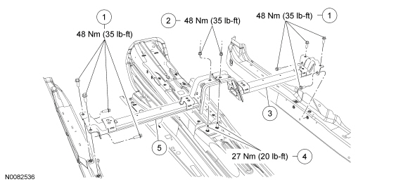
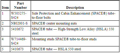
WARNING: Collision damage repair must conform to the instructions contained in this workshop manual. Replacement components must be new, genuine Ford Motor Company parts. Recycled, salvaged, aftermarket or reconditioned parts (including body parts, wheels or safety restraint components) are not authorized by Ford.
Departure from the instructions provided in this manual, including alternate repair methods or the use of substitute components, risks compromising crash safety. Failure to follow these instructions may adversely affect structural integrity and crash safety performance, which could result in serious personal injury to vehicle occupants in a crash.
- NOTE: The Side Protection and Cabin Enhancement (SPACE) tube is
serviced as an assembly only.
Remove the front seats. For additional information, refer to Section 501-10.
- Remove the center console. For additional information, refer to Section 501-12.
- Remove the lower B-pillar trim panel and scuff plate(s). For additional information, refer to Section 501-05.
- Remove the rear seat cushion assembly.
- Release the 2 locking tabs at the front of the seat cushion and remove the seat.
- Remove the rear carpet.
- Remove the 2 pushpins and remove the carpet.
- Remove and discard the 4 SPACE tube-to-floor bolts from the affected
side.
- Remove the center mounting nuts and the console mounting bracket.
Installation
NOTE: Center mounting stud torque needs to be rechecked after removing the nuts. Studs need to maintain torque value of 27 Nm (20 lb-ft).
- Position the SPACE tube and install new tube-to-floor bolts.
- Install the console mount bracket and center mounting nuts.
- Tighten all fasteners to 48 Nm (35 lb-ft).
- Install the rear carpet.
- Install the lower B-pillar trim panel and scuff plate(s). For additional information, refer to Section 501-05.
- Install the rear seat cushion.
- Install the center console. For additional information, refer to Section 501-12.
- Install the front seats. For additional information, refer to Section 501-10.
Side Impact Reinforcement - Police Package
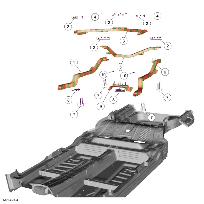
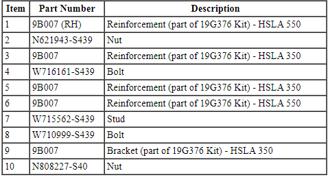
Exploded View
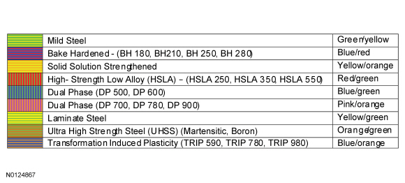
Steel Type Legend
Removal
All
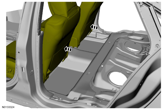
- Remove the rear seat back. For additional information, refer to Section 501-10.
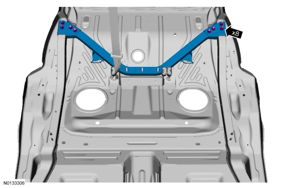
Front Brace
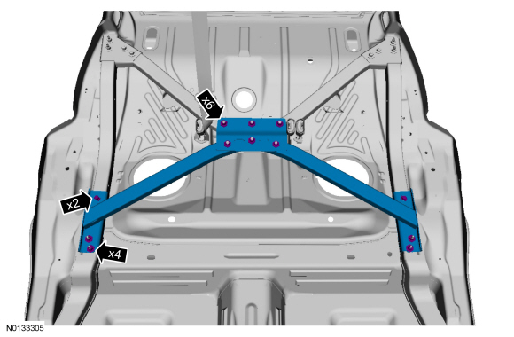
Rear Brace
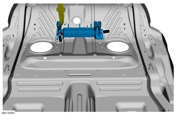
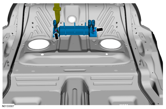
Center Bracket
Side Braces
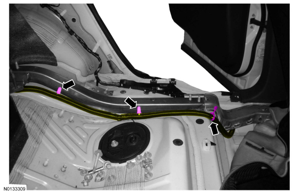
- Remove the rear scuff plates. Refer to Section 501-05.
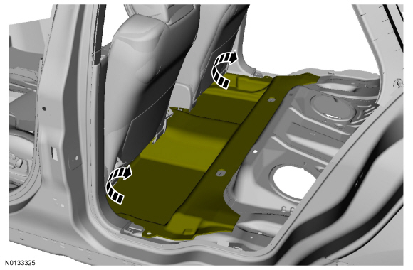
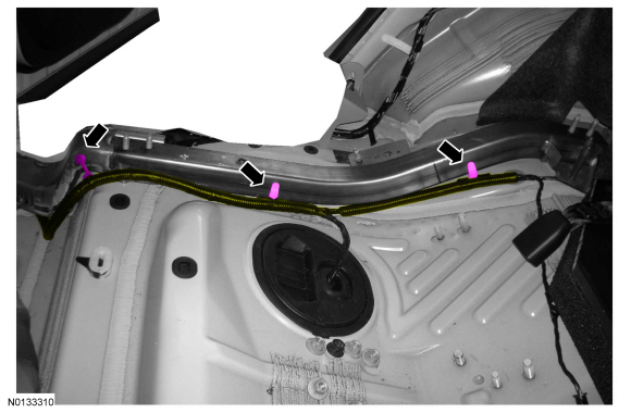
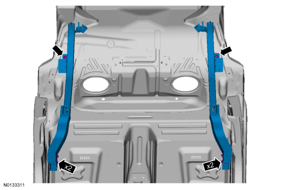
Installation
Center Bracket
- Hand tighten only.
Side Braces
- Hand tighten only.
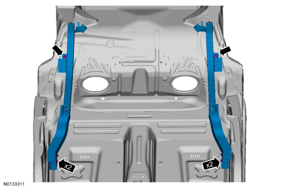
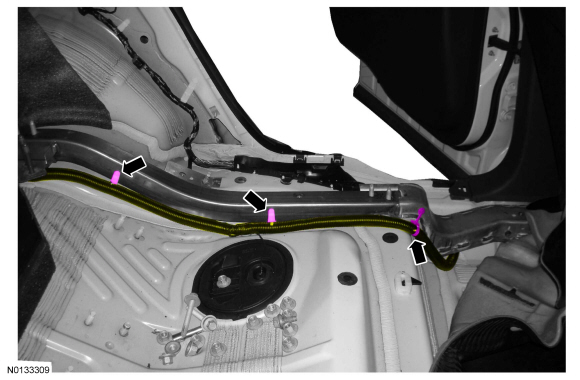
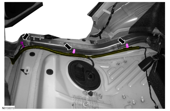
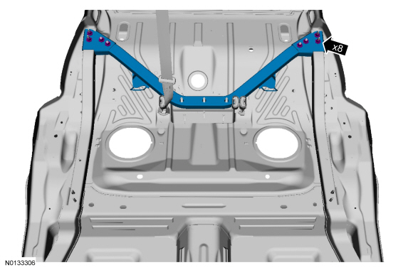
Rear Brace
- NOTE: Make sure the center safety belt is routed over the rear
brace.
Hand tighten only.
Front Brace
- Hand tighten only.
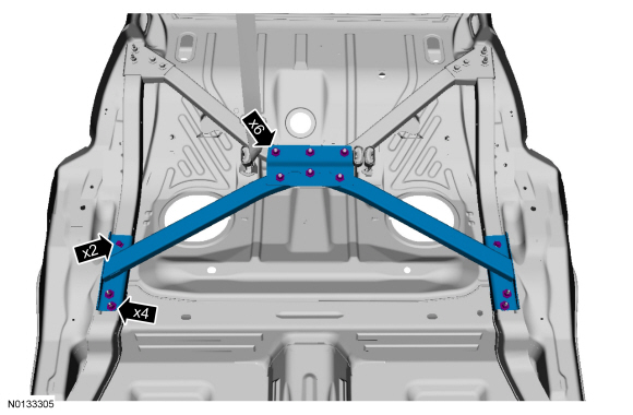
All
-
- Tighten to 55 Nm (41 lb-ft)
-
- Tighten to 55 Nm (41 lb-ft)
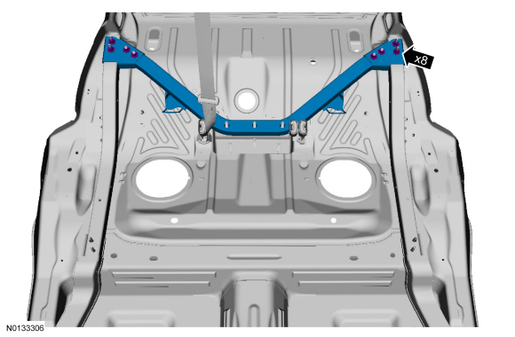
-
- Tighten to 55 Nm (41 lb-ft)
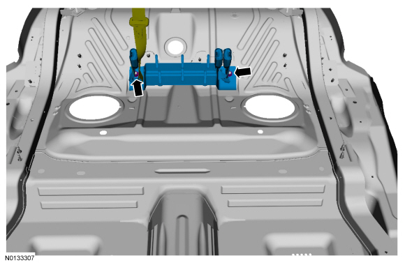
-
- Tighten to 62 Nm (46 lb-ft)
- Tighten to 48 Nm (36 lb-ft)
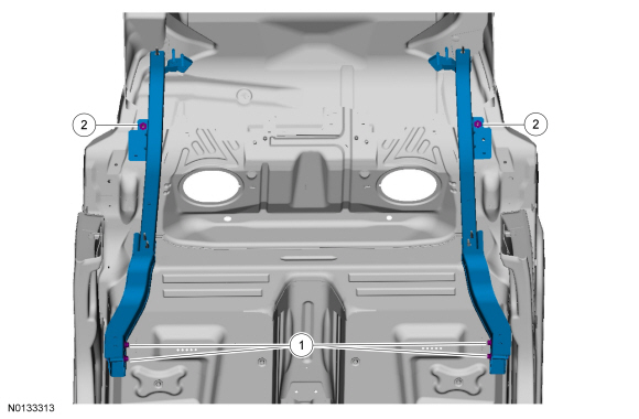
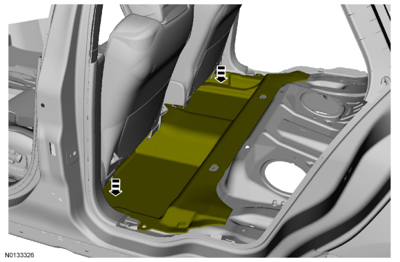
- Install the rear seat back. For additional information, refer to Section 501-10.
- Install the rear scuff plates. Refer to Section 501-05.
Door Outer Panel
Special Tool(s)
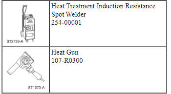
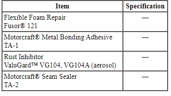
Material
Door Assembly - Exploded View
NOTE: LH front door shown, RH front and rear doors similar. Door intrusion beam is constructed of boron steel and is non-serviceable.
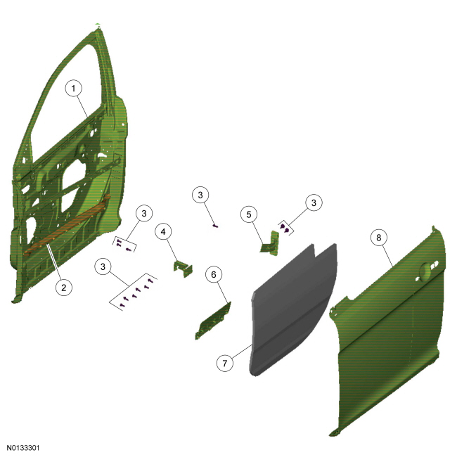
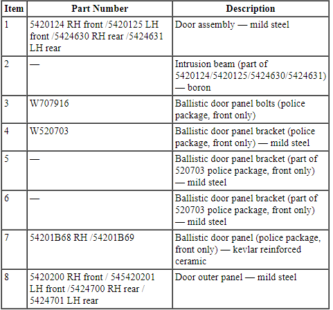
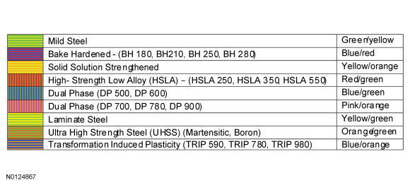
Steel Type Legend
Removal
WARNING: Collision damage repair must conform to the instructions contained in this workshop manual. Replacement components must be new, genuine Ford Motor Company parts. Recycled, salvaged, aftermarket or reconditioned parts (including body parts, wheels or safety restraint components) are not authorized by Ford.
Departure from the instructions provided in this manual, including alternate repair methods or the use of substitute components, risks compromising crash safety. Failure to follow these instructions may adversely affect structural integrity and crash safety performance, which could result in serious personal injury to vehicle occupants in a crash.
WARNING: Invisible ultraviolet and infrared rays emitted in welding can injure unprotected eyes and skin. Always use protection such as a welder's helmet with dark-colored filter lenses of the correct density. Electric welding will produce intense radiation, therefore, filter plate lenses of the deepest shade providing adequate visibility are recommended. It is strongly recommended that persons working in the weld area wear flash safety goggles. Also wear protective clothing. Failure to follow these instructions may result in serious personal injury.
WARNING: Always wear protective equipment including eye protection with side shields, and a dust mask when sanding or grinding. Failure to follow these instructions may result in serious personal injury.
- Remove the door window glass. For additional Information, refer to Section 501-11.
- Remove the door and secure on a work stand. For additional information, refer to Section 501-03.
- Remove the exterior mirror (if equipped). For additional information, refer to Section 501-09.
- Remove the exterior door mouldings. For additional information, refer to Section 501-08.
- Remove the exterior door handle. For additional information, refer to Section 501-14A or Section 501-14B.
- NOTICE: Use care not to drill through the door shell.
Using a spot weld cutter or equivalent, locate and drill out the spot welds on the door panel.
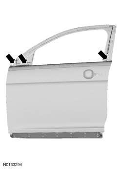
- NOTICE: Use extreme care to avoid cutting the door shell
assembly.
Using a disc grinder, carefully grind along the perimeter of the outer door panel hem to separate the hem edges.
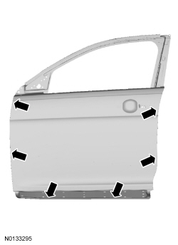
- NOTE: Prior to removing the outer panel, use a sharp knife to cut
the adhesive between the door outer panel, flutter beam, belt line
reinforcement and intrusion beam.
NOTE: The use of a Heat Gun may be required to soften door panel adhesive.
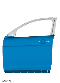
Remove the door outer panel.- Using a flat-blade chisel or equivalent, remove the original panel.
- Using a sharp knife or broad edge scraper, remove the remaining portion of the hem flange from the door shell.
- Remove any remaining adhesive from the door shell flange.
Installation
- Trial fit the service replacement panel to the door shell assembly.
- Prepare the door shell assembly by grinding clean all mating surfaces including the hem area, outer belt reinforcement and intrusion beam.
- Prepare the replacement outer door panel by removing the e-coat on all mating surfaces.
- NOTE: Metal bonding adhesive has a limited working time based on
temperature and humidity. All test fitting and hem flange operations must be
completed before the adhesive is allowed to cure.
Apply metal bonding adhesive to the following areas: service replacement hem flange and outer belt reinforcement-to-outer panel.
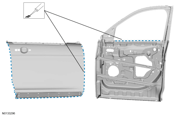
- Partially close the hem flange on the outer panel to the door assembly.
- Using a door panel installation tool or the hammer and dolly method, close the perimeter door hem and smooth any residual adhesive in the joints.
- Install the door assembly on the vehicle and check for correct alignment to all body lines and uniformity to all panel gaps. Adjust as necessary.
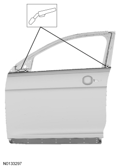
- Clamp the outer door panel to the door shell assembly and spot-weld the door outer panel-to-belt line area using Squeeze-Type Resistance Spot Welding (STRW) duplicating factory spot welds in both location and quantity.
- NOTE: Smooth excess metal panel adhesive squeeze-out in to the
seams to act as a seam sealer.
Remove the door from the vehicle and complete the hem flanging process and repair any damage resulting from the hemming process.
- NOTE: Outer door panel removed for clarity.
Apply flexible foam repair material between the door outer panel and intrusion beam as well as between the outer panel and the anti-flutter beam.
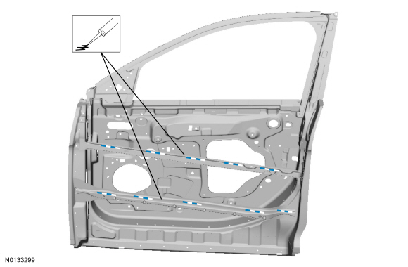
- Sand and prime the flange area using a Ford approved paint system.
- Apply seam sealer to the entire perimeter of the hem flange.
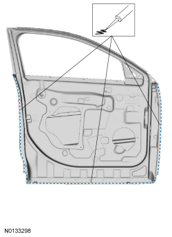
- Refinish the door outer panel-to-door shell repair area using a Ford approved paint system.
- Install the door on the vehicle. For additional information, refer to Section 501-03.
- Restore corrosion protection. For additional information, refer to Restoring Corrosion Protection Following Repair.
- Refinish the exterior of the door assembly using a Ford approved paint system.
- Install the door window glass. For additional information, refer to Section 501-11.
- Install the exterior door handle. For additional information, refer to Section 501-14A or Section 501-14B.
- Install the exterior mirror (if equipped). For additional information, refer to Section 501-09.
- Install the door mouldings. For additional information, refer to Section 501-08.
- Adjust the door to specification. For additional information, refer to Section 501-03.
 General Procedures
Sectioning Guidelines
General Equipment
Material
NOTE: The following illustration provides recommended sectioning
points. Cut lines shown in illustration are approximate.
WARNING:
Coll ...
 Frame and Mounting
Uni-Body, Subframe and Mounting System
SPECIFICATIONS
Torque Specifications
DESCRIPTION AND OPERATION
Subframe and Mounting Systems
The front subframe is bolted to the body and:
aids in structural ...
Other materials:
Fuel consumption
Filling the Tank
The advertised capacity is the indicated capacity and the empty reserve
combined. Indicated capacity is the difference in the amount of fuel in a
full tank and a tank when the fuel gauge indicates empty. Empty reserve
is the amount of fuel in the tank after the fuel gauge indica ...
Headlamp exit delay
You can set the delay time to keep the headlamps on for up to three
minutes after the ignition is turned off.
Follow the steps below to change the delay time (Steps 1 through 6
must be done within 10 seconds):
1. Turn the ignition off.
2. Turn the lighting control to the autolamp position.
...
Cleaning the exterior
Wash your vehicle regularly with cool or lukewarm water and a neutral
pH shampoo, such as Motorcraft® Detail Wash.
• Never use strong household detergents or soap, such as dish washing
or laundry liquid. These products can discolor and spot painted
surfaces.
• Never wash a vehicle that ...
