SPECIFICATIONS
Torque Specifications
a Refer to the procedure in this section.
DESCRIPTION AND OPERATION
Exhaust System
Component Location
The 2.0L Gasoline Turbocharged Direct Injection (GTDI) exhaust system consists of:
- a one-piece catalytic converter manifold that is mounted to the turbocharger outlet flange.
- an exhaust flexible pipe that is mounted to the catalytic converter along with the muffler and tailpipe assembly.
- a resonator which is part of the muffler and tailpipe assembly.
- isolators installed on the body and muffler hangers.
The 3.5L and 3.7L Twin Independent Variable Cam Timing (Ti-VCT) exhaust system consists of:
- a LH one-piece catalytic converter manifold that is mounted to the LH cylinder head.
- a RH one-piece catalytic converter manifold that is mounted to the RH cylinder head
- an exhaust Y-pipe that is mounted to the LH and RH catalytic converters along with the muffler and tailpipe assembly.
- a resonator which is part of the muffler and tailpipe assembly.
- isolators installed on the body and muffler hangers.
The 3.5L GTDI exhaust system consists of:
- two turbocharger-mounted catalytic converters.
- LH and RH exhaust flexible pipes that is mounted to the catalytic converters along with the muffler and tailpipe assembly.
- an underbody catalytic converter.
- a underbody catalytic converter and resonator which is part of the muffler and tailpipe assembly.
- isolators installed on the body and muffler hangers.
Overview
NOTICE: Do not use oil or grease-based lubricants on the isolators. These lubricants may cause deterioration of the rubber. This can lead to separation of the isolator from the exhaust hanger bracket during vehicle operation.
The exhaust system provides an exit for exhaust gases and reduces engine noise by passing exhaust gases through the catalytic converters and a muffler assembly. The catalytic converters also play a major role in reducing air pollutants.
System Operation
2.0L GTDI
Exhaust gases pass through the turbocharger, catalytic converter and then into the exhaust flexible pipe assembly. The exhaust gases then flow through a resonator which is part of the muffler and tailpipe assembly.
3.5L and 3.7L Ti-VCT
Exhaust gases pass through LH and RH catalytic converters into the exhaust Y-pipe assembly. The exhaust gases then flow through a resonator which is part of the muffler and tailpipe assembly.
3.5L GTDI
Exhaust gases pass through the LH and RH turbochargers, catalytic converters and then into the LH and RH exhaust flexible pipes. The exhaust gases then flow through the underbody catalytic converter and a resonator which are both part of the muffler and tailpipe assembly.
DIAGNOSIS AND TESTING
Exhaust System
Inspection and Verification
- Verify the customer concern.
- Visually inspect the components of the exhaust system and related controls that may affect exhaust gas quality or loss of power.
- Visually inspect for obvious signs of mechanical damage. Refer to the following chart.
Visual Inspection Chart
Mechanical
- Exhaust pipe pinched or crushed
- Damaged muffler
- Broken or damaged exhaust hanger brackets
- Damaged catalytic converter
- Cracked exhaust manifold
- Loose or damaged heat shields
- Verify that the exhaust system is installed correctly, with clamps correctly located and tightened to specification.
- If the fault is not visually evident, determine the symptom. GO to Symptom Chart - Exhaust System or GO to Symptom Chart - NVH.
Symptom Chart - Exhaust System
Symptom Chart - NVH
NOTE: NVH symptoms should be identified using the diagnostic tools that are available. For a list of these tools, an explanation of their uses and a glossary of common terms, refer to Section 100-04. Since it is possible any one of multiple systems may be the cause of a symptom, it may be necessary to use a process of elimination type of diagnostic approach to pinpoint the responsible system. If this is not the causal system for the symptom, refer back to Section 100-04 for the next likely system and continue diagnosis.
Pinpoint Test
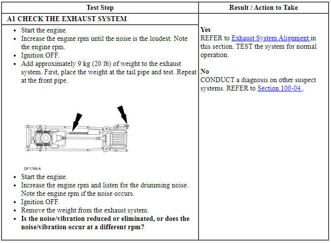
PINPOINT TEST A: DRUMMING NOISE
GENERAL PROCEDURES
Exhaust System Alignment
- With the vehicle in NEUTRAL, position it on a hoist. For additional information, refer to Section 100-02.
- Loosen all fasteners joining the exhaust system components.
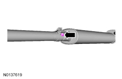
- Beginning at the front of the vehicle, align the exhaust system to establish the maximum clearance. Make sure all fit pipes are pushed all the way into the preceding pipe and the notches are correctly lined up with the tabs.
- Beginning at the front of the vehicle, tighten all fasteners and clamps to specification. For additional information, refer to Specifications in this section.
- Start the engine and check the exhaust system for leaks.
Torca Clamp
- Remove the nut from the Torca clamp.
- Grind the spot weld and the tac weld from the Torca clamp and remove the clamp.
- Clean the uneven surface area and position the new Torca clamp.
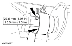
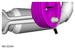
- NOTE: Make sure the clamp position is no more than 27.5 mm (1.08
in) or less than 25.5 mm (1 in) from the inlet of the resonator pipe.
Make sure the back of the slot is covered by the clamp and the button is fully seated inside the notch.
- NOTE: Do not tighten the clamp until the exhaust system has been
aligned.
Tighten the Torca clamp.
- Tighten to 55 Nm (41 lb-ft).
REMOVAL AND INSTALLATION
Catalytic Converter - 2.0L GTDI
Removal
- NOTE: Always install new fasteners and gaskets. Clean flange
faces prior to new gasket installation to make sure of correct sealing.
With the vehicle in NEUTRAL, position it on a hoist. For additional information, refer to Section 100-02.
- Remove the Heated Oxygen Sensor (HO2S) sensor. Refer to Section 303-14.
- Remove the exhaust flexible pipe. For additional information, refer to Exhaust Flexible Pipe - 2.0L GTDI in this section.
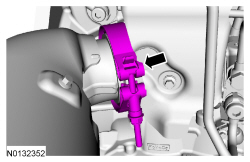
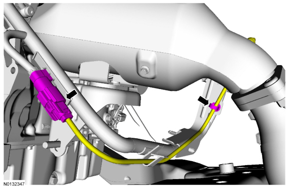
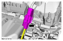
- Disconnect the Catalyst Monitor Sensor Catalyst Monitor Sensor (CMS) electrical connector and detach the wiring clip.

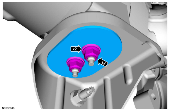
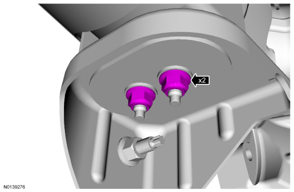
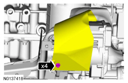
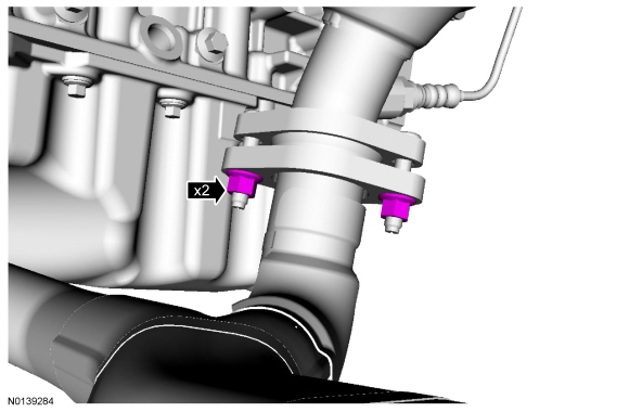
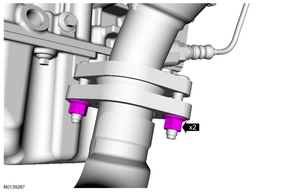
- Remove the 2 catalytic converter-to-bracket nuts, spacer plate and 2 spacers.

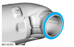
- NOTICE: Removing the catalytic converter-to-turbocharger
outlet flange clamp may be difficult. Use care not to scratch or gouge the
catalytic converter or turbocharger flanges or sealing surfaces. Scratches
and gouges may cause exhaust leaks.
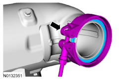
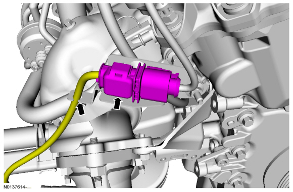
NOTE: Note the position of the catalytic converter-to-turbocharger outlet flange clamp for installation.
Remove and discard the catalytic converter-to-turbocharger outlet flange clamp, then remove the catalytic converter and discard the gasket.
Installation
- Install the new gasket on the catalytic converter.
- NOTE: Position the new catalytic converter-to-turbocharger outlet
flange clamp in the position noted during removal.
Position the new catalytic converter-to-turbocharger outlet flange clamp on the catalytic converter inlet flange.
- NOTE: Do not tighten the 2 catalytic converter-to-bracket nuts at
this time.
Install the catalytic converter along with the catalytic converter-to-bracket spacers, spacer plate and loosely install the 2 nuts.
- Install the new catalytic converter-to-turbocharger outlet flange clamp
over both the catalytic converter inlet flange and the turbocharger outlet
flange.
- Tighten to 20 Nm (177 lb-in).
- Tighten the 2 catalytic converter-to-bracket nuts.
- Tighten to 25 Nm (18 lb-ft).
- Connect the Catalyst Monitor Sensor Catalyst Monitor Sensor (CMS) electrical connector and attach the wiring clip.
- Install the exhaust flexible pipe. For additional information, refer to Exhaust Flexible Pipe - 2.0L GTDI in this section.
- Install the Heated Oxygen Sensor (HO2S) sensor. Refer to Section 303-14.
- Start the engine and check for exhaust leaks.
Catalytic Converter - LH Manifold, 3.5L Ti-VCT
Removal
NOTE: Exhaust fasteners are of a torque prevailing design. Use only new fasteners with the same part number as the original. Torque values must be used as specified during reassembly to make sure of correct retention of exhaust components.
NOTE: Always install new nuts, studs and gaskets. Clean flange faces prior to new gasket installation to make sure of correct sealing.
- With the vehicle in NEUTRAL, position it on a hoist. For additional information, refer to Section 100-02.
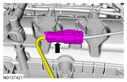
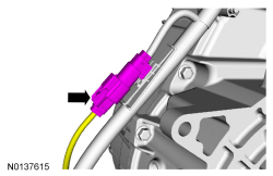
- Disconnect the LH Heated Oxygen Sensor (HO2S) electrical connector.

- Disconnect the LH Catalyst Monitor Sensor (CMS) electrical connector.

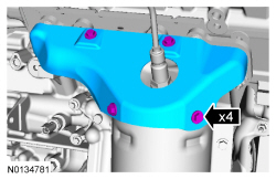
- Remove the 4 bolts and the LH catalytic converter manifold heat shield.

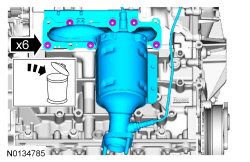
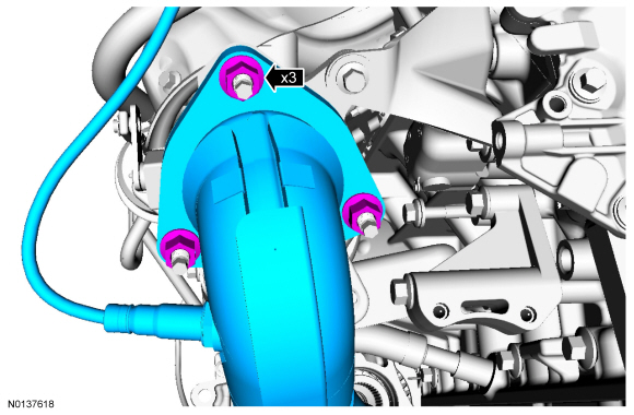
- Remove and discard the top 3 LH catalytic converter manifold-to-cylinder head nuts.
- Remove the exhaust Y-pipe. For additional information, refer to Exhaust Y-Pipe - 3.5L Ti-VCT in this section.
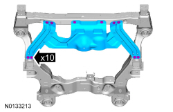
- If equipped, remove the skid plate and the 10 retainers.

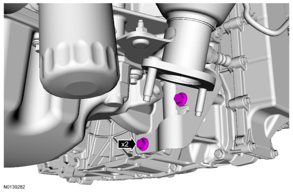
- Remove and discard the lower 3 LH catalytic converter manifold-to-cylinder head nuts.

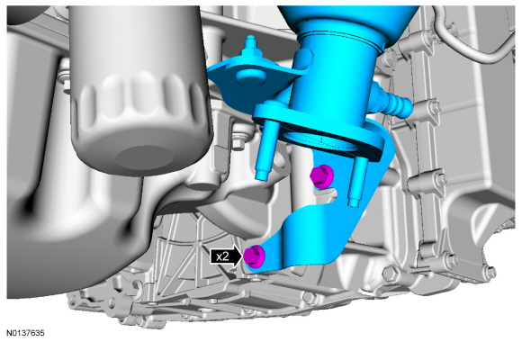
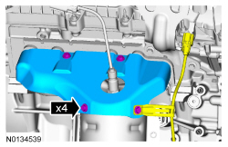
- Remove the 2 LH catalytic converter manifold support
bracket-to-transmission bolts.
- Remove the LH catalytic converter manifold and discard the gasket.

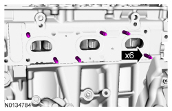
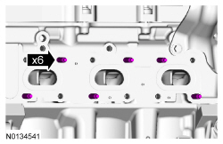
- Remove and discard the 6 LH catalytic converter manifold-to-cylinder head studs.

Installation
- Install 6 new LH catalytic converter manifold-to-cylinder head studs.
- Tighten to 12 Nm (106 lb-in).
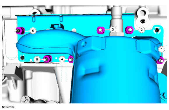
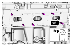
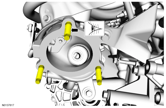
- NOTICE: Failure to tighten the catalytic converter manifold
nuts to specification a second time will cause the exhaust manifold to
develop an exhaust leak.
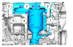
Using a new gasket, install the LH catalytic converter manifold and 6 new nuts. Tighten in 2 stages in the sequence shown:
- Stage 1: Tighten to 25 Nm (18 lb-ft).
- Stage 2: Tighten to 25 Nm (18 lb-ft).
- Install the 2 catalytic converter manifold support
bracket-to-transmission bolts.
- Tighten to 48 Nm (35 lb-ft).
- If equipped, install the skid plate and the 10 retainers.
- Tighten to 70 Nm (52 lb-ft).
- Install the exhaust Y-pipe. For additional information, refer to Exhaust Y-Pipe - 3.5L Ti-VCT in this section.
- Install the catalytic converter manifold heat shield and the 4 bolts.
- Tighten to 10 Nm (89 lb-in).

- Connect the LH Catalyst Monitor Sensor (CMS) electrical connector.

- Connect the LH Heated Oxygen Sensor (HO2S) electrical connector.
Catalytic Converter - LH Manifold, 3.7L Ti-VCT
Removal
NOTE: Exhaust fasteners are of a torque prevailing design. Use only new fasteners with the same part number as the original. Torque values must be used as specified during reassembly to make sure of correct retention of exhaust components.
NOTE: Always install new nuts, studs and gaskets. Clean flange faces prior to new gasket installation to make sure of correct sealing.
- With the vehicle in NEUTRAL, position it on a hoist. For additional information, refer to Section 100-02.
- Disconnect the LH Heated Oxygen Sensor (HO2S) electrical connector.

- Disconnect the LH Catalyst Monitor Sensor (CMS) electrical connector.
- Remove the 4 bolts and the LH catalytic converter manifold heat shield.

- Remove and discard the top 3 LH catalytic converter manifold-to-cylinder head nuts.

- Remove the exhaust Y-pipe. For additional information, refer to Exhaust Y-Pipe - 3.7L Ti-VCT in this section.
- If equipped, remove the skid plate and the 10 retainers.

- Remove and discard the lower 3 LH catalytic converter manifold-to-cylinder head nuts.
- Remove the 2 LH catalytic converter manifold support
bracket-to-transmission bolts.
- Remove the LH catalytic converter manifold and discard the gasket.
- Remove and discard the 6 LH catalytic converter manifold-to-cylinder head studs.
Installation
- Install 6 new LH catalytic converter manifold-to-cylinder head studs.
- Tighten to 12 Nm (106 lb-in).

- NOTICE: Failure to tighten the catalytic converter manifold
nuts to specification a second time will cause the exhaust manifold to
develop an exhaust leak.
Using a new gasket, install the LH catalytic converter manifold and 6 new nuts. Tighten in 2 stages in the sequence shown:
- Stage 1: Tighten to 25 Nm (18 lb-ft).
- Stage 2: Tighten to 25 Nm (18 lb-ft).

- Install the 2 catalytic converter manifold support
bracket-to-transmission bolts.
- Tighten to 48 Nm (35 lb-ft).

- If equipped, install the skid plate and the 10 retainers.
- Tighten to 70 Nm (52 lb-ft).

- Install the exhaust Y-pipe. For additional information, refer to Exhaust Y-Pipe - 3.7L Ti-VCT in this section.
- Install the catalytic converter manifold heat shield and the 4 bolts.
- Tighten to 10 Nm (89 lb-in).
- Connect the LH Catalyst Monitor Sensor (CMS) electrical connector.

- Connect the LH Heated Oxygen Sensor (HO2S) electrical connector.

Catalytic Converter - RH Manifold, 3.5L Ti-VCT
Removal
All vehicles
NOTE: Always install new fasteners and gaskets. Clean flange faces prior to new gasket installation to make sure of correct sealing.
- With the vehicle in NEUTRAL, position it on a hoist. For additional information, refer to Section 100-02.
- Disconnect the RH Catalyst Monitor Sensor (CMS) electrical connector.

- Disconnect the RH Heated Oxygen Sensor (HO2S) electrical connector.

- Remove the 4 bolts and the RH catalytic converter heat shield.
- Remove the exhaust Y-pipe. For additional information, refer to Exhaust Y-Pipe - 3.5L Ti-VCT in this section.
- Remove the 4 bolts and position aside the Electronic Power Assist Steering (EPAS) shield.

All-Wheel Drive (AWD) vehicles
- Remove the transaxle support insulator - anti roll, 3.5L Ti-VCT. For additional information, refer to Section 307-01A.
All vehicles
- Remove the 6 nuts and the RH catalytic converter manifold.
- Discard the nuts and RH catalytic converter manifold gasket.
- Remove and discard the 6 RH catalytic converter manifold studs.

Installation
All vehicles
- Install 6 new RH catalytic converter manifold studs.
- Tighten to 12 Nm (106 lb-in).
- NOTICE: Failure to tighten the catalytic converter manifold
nuts to specification a second time will cause the exhaust manifold to
develop an exhaust leak.
Using a new gasket, install the RH catalytic converter manifold and 6 new nuts. Tighten in 2 stages in the sequence shown:
- Stage 1: Tighten to 20 Nm (177 lb-in).
- Stage 2: Tighten to 25 Nm (18 lb-ft).

All-Wheel Drive (AWD) vehicles
- Install the transaxle support insulator - anti roll, 3.5L Ti-VCT. For additional information, refer to Section 307-01A.
All vehicles
- Position back the Electronic Power Assist Steering (EPAS) shield and
install the 4 bolts
- Tighten to 11 Nm (97 lb-in).
- Install the exhaust Y-pipe. For additional information, refer to Exhaust Y-Pipe - 3.5L Ti-VCT in this section.
- Install the RH catalytic converter manifold heat shield, Catalyst
Monitor Sensor (CMS) wiring harness bracket and the 4 bolts.
- Tighten to 10 Nm (89 lb-in).

- Connect the RH Heated Oxygen Sensor (HO2S) electrical connector.

- Connect the RH Catalyst Monitor Sensor (CMS) electrical connector.

Catalytic Converter - RH Manifold, 3.7L Ti-VCT
Removal
All vehicles
NOTE: Always install new fasteners and gaskets. Clean flange faces prior to new gasket installation to make sure of correct sealing.
- With the vehicle in NEUTRAL, position it on a hoist. For additional information, refer to Section 100-02.
- Disconnect the RH Catalyst Monitor Sensor (CMS) electrical connector.

- Disconnect the RH Heated Oxygen Sensor (HO2S) electrical connector.

- Remove the 4 bolts and the RH catalytic converter heat shield.

- Remove the exhaust Y-pipe. For additional information, refer to Exhaust Y-Pipe - 3.7L Ti-VCT in this section.
- Remove the 4 bolts and position aside the Electronic Power Assist Steering (EPAS) shield.

All-Wheel Drive (AWD) vehicles
- Remove the transaxle support insulator - anti roll, 3.7L Ti-VCT. For additional information, refer to Section 307-01A.
All vehicles
- Remove the 6 nuts and the RH catalytic converter manifold.
- Discard the nuts and RH catalytic converter manifold gasket.

- Remove and discard the 6 RH catalytic converter manifold studs.
Installation
All vehicles
- Install 6 new RH catalytic converter manifold studs.
- Tighten to 12 Nm (106 lb-in).

- NOTICE: Failure to tighten the catalytic converter manifold
nuts to specification a second time will cause the exhaust manifold to
develop an exhaust leak.
Using a new gasket, install the RH catalytic converter manifold and 6 new nuts. Tighten in 2 stages in the sequence shown:
- Stage 1: Tighten to 20 Nm (177 lb-in).
- Stage 2: Tighten to 25 Nm (18 lb-ft).
All-Wheel Drive (AWD) vehicles
- Install the transaxle support insulator - anti roll, 3.7L Ti-VCT. For additional information, refer to Section 307-01A.
All vehicles
- Position back the Electronic Power Assist Steering (EPAS) shield and
install the 4 bolts
- Tighten to 11 Nm (97 lb-in).

- Install the exhaust Y-pipe. For additional information, refer to Exhaust Y-Pipe - 3.7L Ti-VCT in this section.
- Install the RH catalytic converter manifold heat shield, Catalyst
Monitor Sensor (CMS) wiring harness bracket and the 4 bolts.
- Tighten to 10 Nm (89 lb-in).

- Connect the RH Heated Oxygen Sensor (HO2S) electrical connector.
- Connect the RH Catalyst Monitor Sensor (CMS) electrical connector.
Catalytic Converter - LH, 3.5L GTDI
Removal
NOTE: Always install new fasteners and gaskets. Clean flange faces prior to new gasket installation to make sure of correct sealing.
- With the vehicle in NEUTRAL, position it on a hoist. For additional information, REFER to Section 100-02.
- Remove the LH HO2S. For additional information, REFER to Section 303-14.
- Remove the LH exhaust flexible pipe. For additional information, refer to Exhaust Flexible Pipe - LH, 3.5L GTDI in this section.
- If equipped, remove the 10 retainers and the skid plate.

- Disconnect the LH CMS electrical connector.

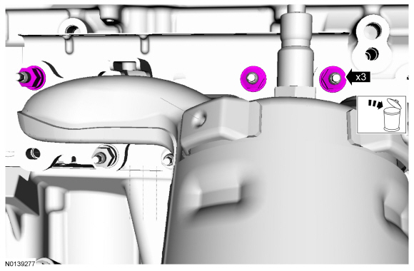
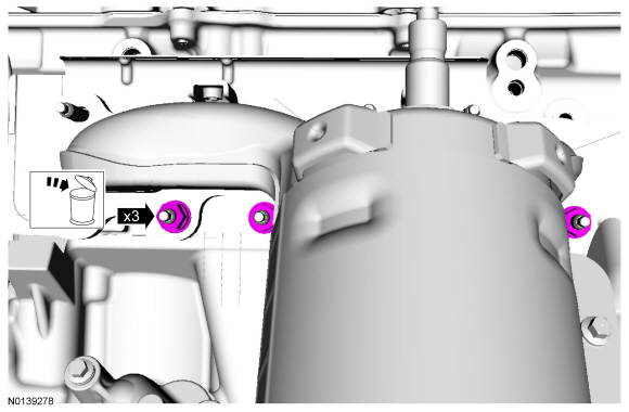
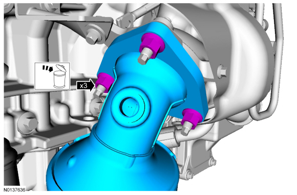
- Remove the 3 LH catalytic converter-to-turbocharger nuts and the
catalytic converter.
- Discard the nuts and gasket.
Installation
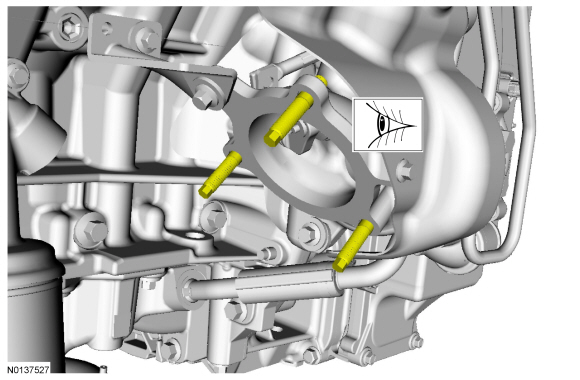
- Inspect the LH turbocharger-to-catalytic converter studs for damage.
- If damaged or if a stud comes out when removing the nut, replace the stud.
- Tighten to 25 Nm (18 lb-ft).
- NOTICE: Failure to tighten the LH catalytic converter
manifold-to-turbocharger nuts to specification a second time will cause the
LH catalytic converter manifold-to-turbocharger to develop an exhaust leak.
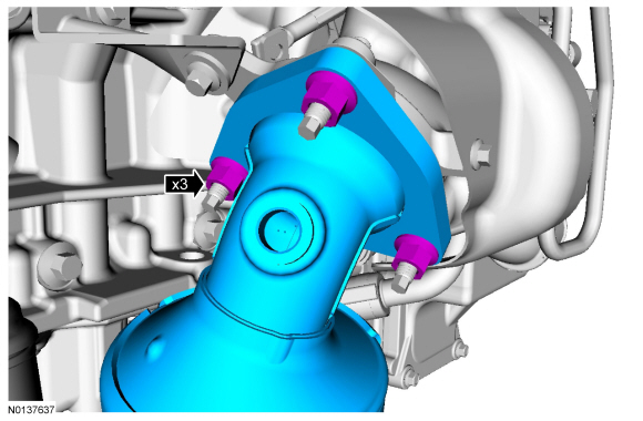
Using a new gasket and 3 new nuts, install the LH catalytic converter manifold to the turbocharger. Tighten the LH catalytic converter manifold in 2 stages.
- Stage 1: Tighten to 40 Nm (30 lb-ft).
- Stage 2: Tighten to 40 Nm (30 lb-ft).
- Connect the LH CMS electrical connector.
- If equipped, install the skid plate and the 10 retainers.
- Tighten to 70 Nm (52 lb-ft).

- Install the LH exhaust flexible pipe. For additional information, refer to Exhaust Flexible Pipe - LH, 3.5L GTDI in this section.
- Install the LH HO2S. For additional information, REFER to Section 303-14.
Catalytic Converter - RH, 3.5L GTDI
Removal
NOTE: Always install new fasteners and gaskets. Clean flange faces prior to new gasket installation to make sure of correct sealing.
- With the vehicle in NEUTRAL, position it on a hoist. For additional information, REFER to Section 100-02.
- Remove the RH front wheel and tire. For additional information, REFER to Section 204-04.
- Disconnect the RH HO2S electrical connector.
- Detach the HO2S electrical connector retainer and wire from the bracket.

- Remove the LH and RH exhaust flexible pipes. For additional information, refer to Exhaust Flexible Pipe - LH, 3.5L GTDI and Exhaust Flexible Pipe - RH, 3.5L GTDI in this section.
- Disconnect the RH CMS electrical connector.

- Remove the 3 RH catalytic converter-to-turbocharger nuts and the
converter.
- Discard the nuts and gasket.

Installation
- Inspect the RH turbocharger-to-catalytic converter studs for damage.
- If damaged or if a stud comes out when removing the nut, replace the stud.
- Tighten to 25 Nm (18 lb-ft).
- NOTICE: Failure to tighten the RH catalytic converter
manifold-to-turbocharger nuts to specification a second time will cause the
RH catalytic converter manifold-to-turbocharger to develop an exhaust leak.
NOTICE: Prior to installation, inspect the HO2S and the CMS wiring harness for damage.
Using a new gasket and 3 new nuts, install the RH catalytic converter manifold to the turbocharger. Tighten the RH catalytic converter manifold in 2 stages.- Stage 1: Tighten to 40 Nm (30 lb-ft).
- Stage 2: Tighten to 40 Nm (30 lb-ft).
- Connect the RH CMS electrical connector.
- Install the LH and RH exhaust flexible pipes. For additional information, refer to Exhaust Flexible Pipe - LH, 3.5L GTDI and Exhaust Flexible Pipe - RH, 3.5L GTDI in this section.
- Connect the RH HO2S electrical connector.
- Attach the HO2S electrical connector retainer and wire to the bracket.
- Install the RH front wheel and tire. For additional information, REFER to Section 204-04.
Catalytic Converter - Underbody
- The production underbody catalytic converter and muffler assembly is serviced as one part. For additional information, refer to Muffler and Tailpipe in this section.
Exhaust Y-Pipe - 3.5L Ti-VCT
Removal
NOTE: Always install new fasteners and gaskets. Clean flange faces prior to new gasket installation to make sure of correct sealing.
- With the vehicle in NEUTRAL, position it on a hoist. For additional information, refer to Section 100-02.
- Loosen the Torca clamp retainer.

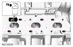
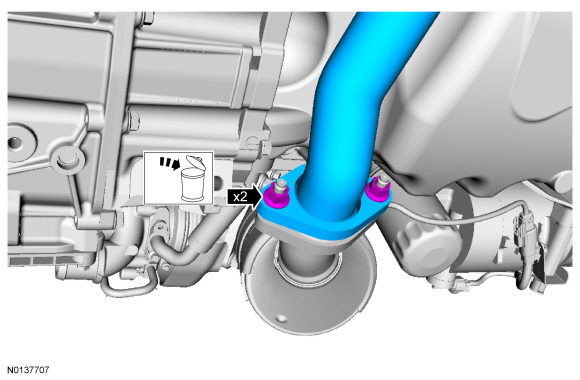
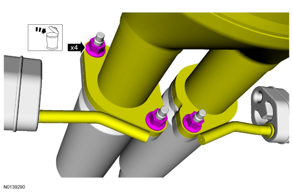
- NOTICE: Do not damage or tear the isolator during removal.
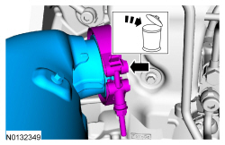
Using soapy water, separate the isolator from the exhaust Y-pipe.

- Remove and discard the 2 exhaust Y-pipe-to-LH catalytic converter
manifold nuts.
- Discard the gasket.
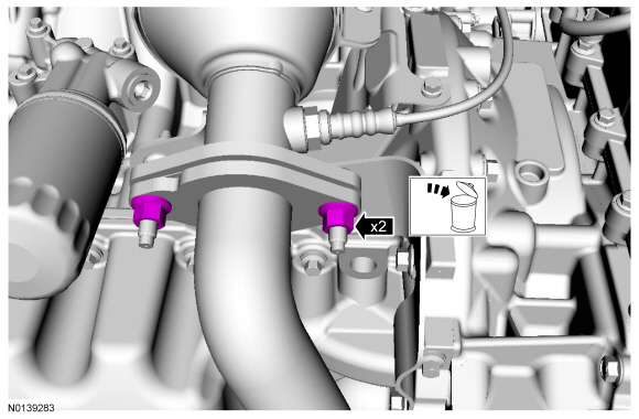
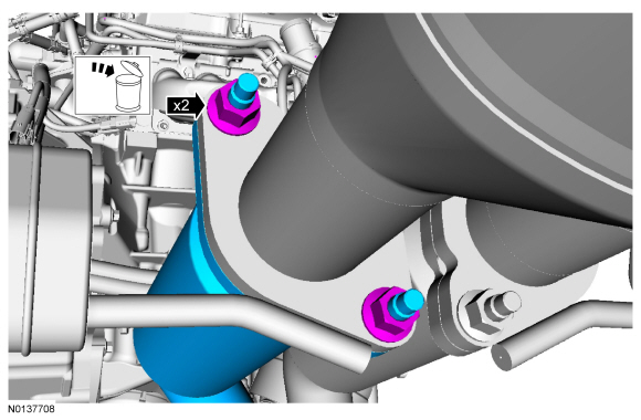
- Remove and discard the 2 exhaust Y-pipe-to-RH catalytic converter nuts.
- Remove the exhaust Y-pipe.
Installation
NOTE: Always install new fasteners and gaskets. Clean flange faces prior to new gasket installation to make sure of correct sealing.
- Install the exhaust Y-pipe with a new gasket and nuts.
- Using soapy water, attach the isolator to the exhaust Y-pipe.
- Hand-tighten all fasteners.

- Tighten the exhaust Y-pipe-to-LH catalytic converter manifold nuts.
- Tighten to 40 Nm (30 lb-ft).
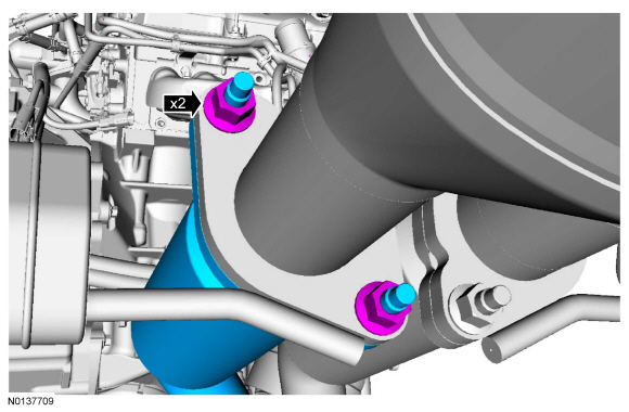
- Tighten the exhaust Y-pipe-to-RH catalytic converter nuts.
- Alternately tighten the 2 nuts to 40 Nm (30 lb-ft).
- Tighten the Torca clamp retainer.
- Tighten to 55 Nm (41 lb-ft).

Exhaust Y-Pipe - 3.7L Ti-VCT
Removal
NOTICE: Do not excessively bend, twist or allow the exhaust to hang from the flexible pipe or damage to the exhaust system may occur.
- NOTE: Always install new fasteners and gaskets. Clean flange
faces prior to new gasket installation to make sure of correct sealing.
With the vehicle in NEUTRAL, position it on a hoist. For additional information, refer to Section 100-02.
- Remove the 4 exhaust Y-pipe-to-muffler and tailpipe flange nuts.
- Discard the nuts and gasket.
- Remove and discard the 2 exhaust Y-pipe-to-LH catalytic converter
manifold nuts.
- Discard the gasket.
- Remove and discard the 2 exhaust Y-pipe-to-RH catalytic converter
manifold nuts.
- Remove the exhaust Y-pipe.
Installation
NOTICE: Do not excessively bend, twist or allow the exhaust to hang from the flexible pipe or damage to the exhaust system may occur.
- Install the exhaust Y-pipe with new gaskets and nuts.
- Hand-tighten all fasteners.
- Tighten the exhaust Y-pipe-to-LH catalytic converter manifold nuts.
- Alternately tighten the 2 nuts to 40 Nm (30 lb-ft).

- Tighten the exhaust Y-pipe-to-RH catalytic converter manifold nuts.
- Alternately tighten the 2 nuts to 40 Nm (30 lb-ft).
- Tighten the exhaust Y-pipe-to-muffler and tail pipe flange nuts.
- Tighten to 40 Nm (30 lb-ft).
Exhaust Flexible Pipe - 2.0L GTDI
Removal
- NOTE: Always install new fasteners and gaskets. Clean flange
faces prior to new gasket installation to make sure of correct sealing.
With the vehicle in NEUTRAL, position it on a hoist. For additional information, refer to Section 100-02.
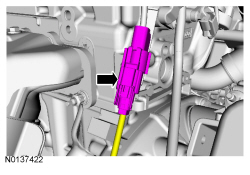
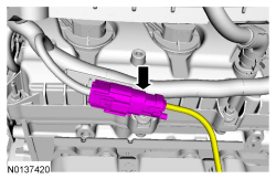
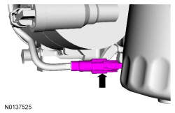
- Loosen the Torca clamp retainer.
- To install, tighten to 55 Nm (41 lb-ft).
- NOTE: Do not damage or tear the isolator during removal.
Using soapy water, detach the exhaust flexible pipe isolator.
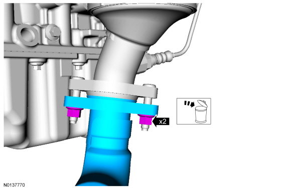
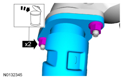
- NOTE: Install a new gasket and 2 new nuts.
Remove the flexible pipe and discard the 2 nuts and gasket.
- To install, tighten to 40 Nm (30 lb-ft).
Installation
- To install, reverse the removal procedure.
Exhaust Flexible Pipe - LH, 3.5L GTDI
Removal
NOTICE: Do not excessively bend, twist or allow the exhaust to hang from the flexible pipe or damage to the exhaust system may occur.
- With the vehicle in NEUTRAL, position it on a hoist. For additional information, REFER to Section 100-02.
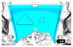
- If equipped, release the 4 retainers and remove the underbody shield.

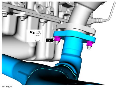
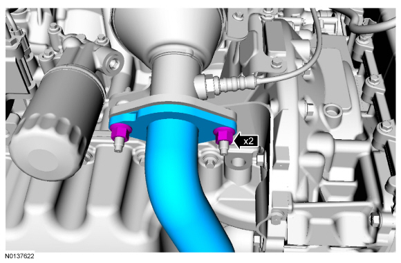
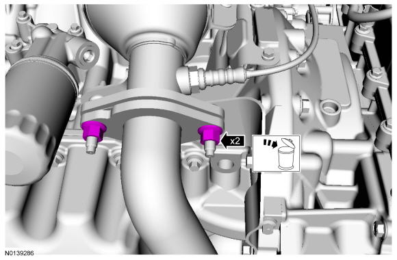
- Remove the 2 LH exhaust flexible pipe-to-LH catalytic converter nuts.
- Discard the nuts.
- Remove the 2 LH exhaust flexible pipe-to-underbody catalytic converter
nuts.
- Discard the nuts and gasket.
- Remove the LH exhaust flexible pipe.
Installation
NOTICE: Do not excessively bend, twist or allow the exhaust to hang from the flexible pipe or damage to the exhaust system may occur.
- Install the LH exhaust flexible pipe with a new gasket and fasteners.
- Hand-tighten all fasteners.
- Tighten the LH exhaust flexible pipe-to-underbody catalytic converter
nuts.
- Tighten to 40 Nm (30 lb-ft).
- NOTE: Make sure the LH exhaust flexible pipe is straight and is
approximately 25 mm (0.984 in) from all components.
Tighten the LH exhaust flexible pipe-to-LH catalytic converter nuts.
- Alternately tighten the 2 nuts to 40 Nm (30 lb-ft).

- If equipped, install the 4 retainers and the underbody shield.
Exhaust Flexible Pipe - RH, 3.5L GTDI
Removal
NOTICE: Do not excessively bend, twist or allow the exhaust to hang from the flexible pipe or damage to the exhaust system may occur.
- With the vehicle in NEUTRAL, position it on a hoist. For additional information, REFER to Section 100-02.
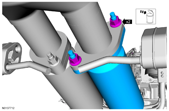
- Remove the 2 RH exhaust flexible pipe-to-RH catalytic converter bolts.
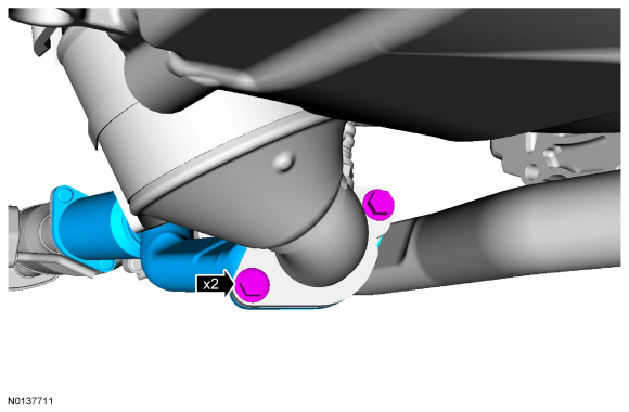
- Remove the 2 RH exhaust flexible pipe-to-underbody catalytic converter
nuts.
- Discard the nuts and gaskets.
- Remove the RH exhaust flexible pipe.
Installation
NOTICE: Do not excessively bend, twist or allow the exhaust to hang from the flexible pipe or damage to the exhaust system may occur.
- Install the RH exhaust flexible pipe with new gaskets and fasteners.
- Hand-tighten all fasteners.
- Tighten the RH exhaust flexible pipe-to-underbody catalytic converter
nuts.
- Tighten to 40 Nm (30 lb-ft).

- Tighten the RH exhaust flexible pipe-to-RH catalytic converter bolts.
- Tighten to 40 Nm (30 lb-ft).

Resonator
Removal and Installation
- The production resonator and muffler and tailpipe are serviced as one part. For additional information, refer to Muffler and Tailpipe in this section.
Muffler and Tailpipe
Removal
NOTICE: Do not use oil or grease-based lubricants on the isolators. They may cause deterioration of the rubber.
NOTICE: Oil or grease-based lubricants on the isolators may cause the exhaust isolator to separate from the exhaust hanger bracket during vehicle operation.
NOTE: Always install new fasteners and gaskets. Clean flange faces prior to new gasket installation to make sure of correct sealing.
All vehicles
- With the vehicle in NEUTRAL, position it on a hoist. For additional information, refer to Section 100-02.
3.5L Ti-VCT vehicles
- Loosen the Torca clamp nut.
- To install, tighten to 55 Nm (41 lb-ft).

- NOTICE: Do not damage or tear the isolators during removal.
Using soapy water, separate the 4 isolators and remove the muffler and tailpipe assembly from the vehicle.
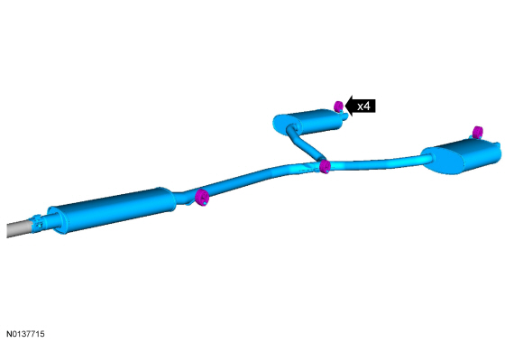
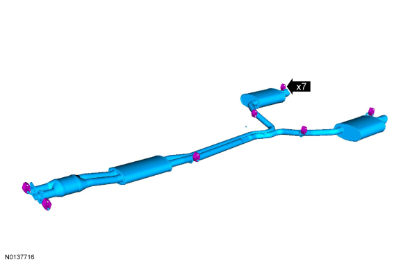
3.7L Ti-VCT and 3.5L GTDI vehicles
NOTE: 3.5L GTDI shown. 3.7L Ti-VCT similar.
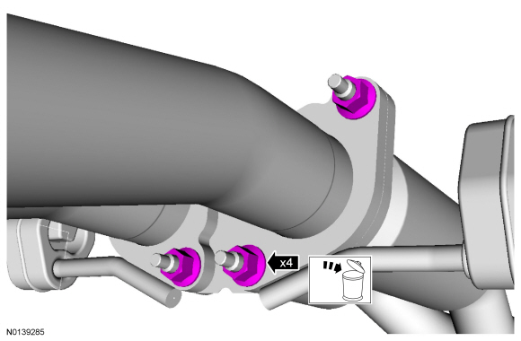
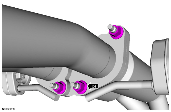
- Remove the 4 LH and RH exhaust flexible pipes-to-underbody catalytic
converter nuts.
- Discard the nuts and gaskets.
- To install, tighten to 40 Nm (30 lb-ft).
- NOTICE: Do not damage or tear the isolators during removal.
Using soapy water, separate the 7 isolators and remove the muffler and tailpipe assembly from the vehicle.
Installation
NOTE: Always install new fasteners and gaskets. Clean flange faces prior to new gasket installation to make sure of correct sealing.
- To install, reverse the removal procedure.
 Transfer Case - Power Transfer Unit (PTU)
SPECIFICATIONS
Material
Torque Specifications
a Refer to the procedure in this section.
DESCRIPTION AND OPERATION
Power Transfer Unit (PTU)
The AWD system consists of the following:
...
 Fuel System
...
Other materials:
Changing the wiper blades
1. Pull the wiper blade and arm away
from the glass.
2. Squeeze the locking tabs to release
the blade from the arm and pull the
blade away from the arm to remove it.
3. Attach the new blade to the arm
and snap it into place.
Replace wiper blades at least once per
year for optimum per ...
Transaxle/Transmission Cooling - 6F35
SPECIFICATIONS
Material
Torque Specifications
DESCRIPTION AND OPERATION
Transaxle Cooling
The transmission fluid cooling system consists of the following:
OTA transmission fluid cooler
Front transmission fluid cooler tube assembly
Rear transmission fluid cooler tube assembly
Transmission ...
Waxing
Regular waxing is necessary to protect the paint on your car from the
elements. We recommend that you wash and wax the painted surface
once or twice a year.
When washing and waxing, park your vehicle in a shaded area out of
direct sunlight. Always wash your vehicle before applying wax.
• ...
