Block Heater - 2.0L GTDI
Removal
NOTE: Removal steps in this procedure may contain installation details.
- Drain the cooling system. For additional information, refer to Cooling System Draining, Filling and Bleeding in this section.
- NOTICE: To install, route the block heater power cable away from hot or rotating components, or the cable can be damaged.
-
- To install, tighten to 40 Nm (30 lb-ft).
Installation
- To install, reverse the removal procedure.
- Fill the cooling system. For additional information, refer to Cooling System Draining, Filling and Bleeding in this section.
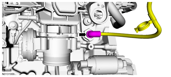
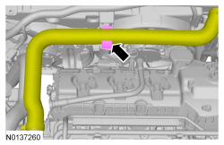
Block Heater - 3.5L GTDI, 3.5L Ti-VCT, 3.7L Ti-VCT
NOTE: 3.5L shown, 3.7L Ti-VCT, 3.5L Gasoline Turbocharged Direct Injection (GTDI) similar.
Removal and Installation
All engines
- Drain the cooling system. For additional information, refer to Cooling System Draining, Filling and Bleeding in this section.
3.5L engine
- Remove the RH catalytic converter. For additional information, refer to Section 309-00.
3.5L Gasoline Turbocharged Direct Injection (GTDI) engine
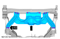
- Remove the RH front wheel and tire. For additional information, refer to Section 204-04.
- If equipped, remove the 4 retainers and the underbody shield.
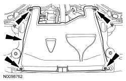
- If equipped, remove the 10 bolts and the skid plate.
- To install, tighten to 70 Nm (52 lb-ft).

All engines
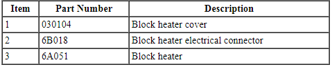
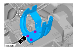
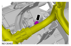
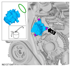
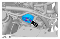
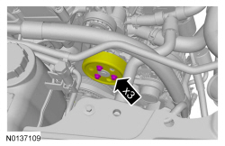
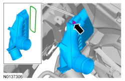
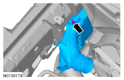
- Remove the block heater cover.
- NOTICE: Make sure that the block heater wiring is routed and
secured away from rotating or hot components, or damage to the wiring may
occur.
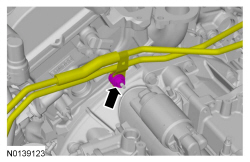
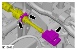
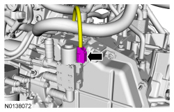
Disconnect the block heater electrical connector.
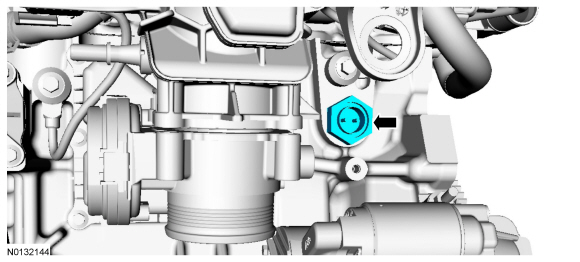
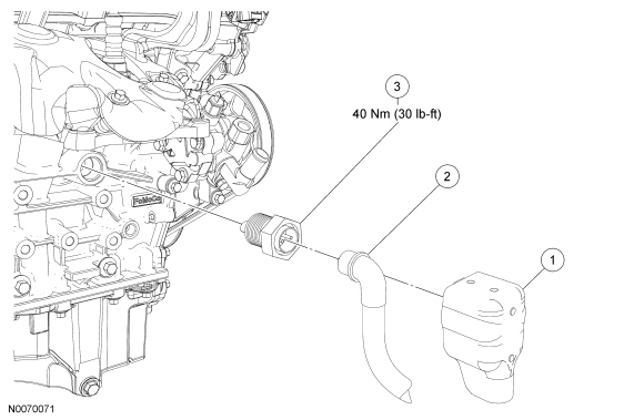
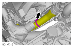
- Remove the block heater.
- To install, tighten to 40 Nm (30 lb-ft).
- To install, reverse the removal procedure.
- Fill and bleed the cooling system. For additional information, refer to Cooling System Draining, Filling and Bleeding in this section.
Thermostat - 3.5L Ti-VCT, 3.7L Ti-VCT
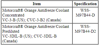
Material
Removal and Installation
- Drain the cooling system. Refer to Cooling System Draining, Filling and Bleeding.
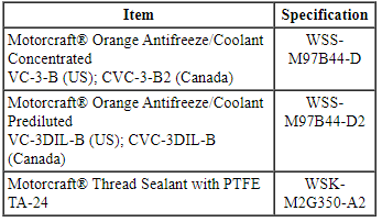
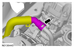
- Remove the engine ACL outlet pipe. Refer to Section 303-12.
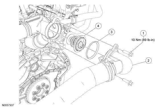
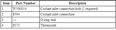
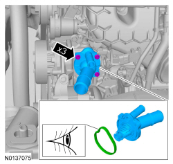
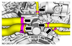
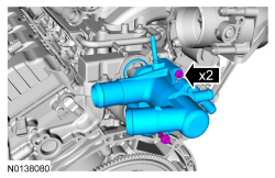
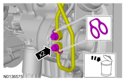
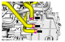
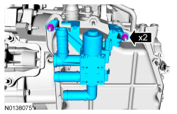
- Remove the 2 bolts and position the coolant inlet connection aside.
- To install, tighten to 10 Nm (89 lb-in).
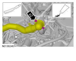
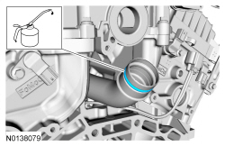
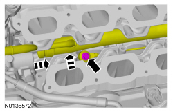
- Remove the O-ring seal and thermostat.
- Clean and inspect the O-ring seal. Install a new seal if necessary.
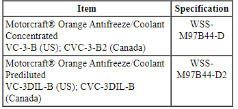
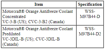
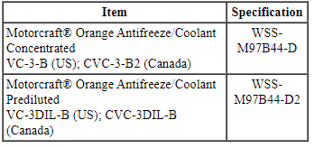
- NOTICE: Use Motorcraft Orange Antifreeze/Coolant. Do not mix
coolant types. Mixing coolant types degrades the coolant corrosion
protection and may damage the engine or cooling system.
NOTE: Lubricate the thermostat O-ring seal with clean engine coolant.
To install, reverse the removal procedure.
- Fill and bleed the cooling system. Refer to Cooling System Draining, Filling and Bleeding.
Thermostat - 3.5L GTDI
Material
Removal
NOTE: Removal steps in this procedure may contain installation details.
- Drain the cooling system. Refer to Cooling System Draining, Filling and Bleeding.
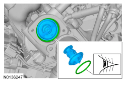
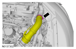
- Remove the ACL outlet pipe. For additional information, refer to Section 303-12.
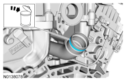
- Wire brush. Apply the substance from the specified tube.
- Material: Thread Sealant with PTFE.
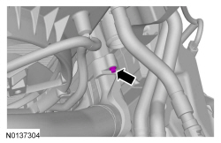
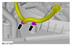
- To install, tighten to 10 Nm (89 lb-in).
- Visual check.
Installation
- To install, reverse the removal procedure.
- Fill and bleed the cooling system. Refer to Cooling System Draining, Filling and Bleeding.
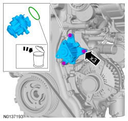
Thermostat Housing - 2.0L GTDI
Removal
NOTE: Removal steps in this procedure may contain installation details.
- Drain the cooling system. For additional information, refer to Cooling System Draining, Filling and Bleeding in this section.
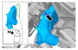
- NOTICE: Cover the generator to prevent coolant contamination
of the generator.
Completely cover the generator with waterproof plastic.
- Visual check.
-
- To install, tighten to 10 Nm (89 lb-in).
Installation
- To install, reverse the removal procedure.
- Make sure the plastic covering the generator is removed.
- Fill and bleed the cooling system. For additional information, refer to Cooling System Draining, Filling and Bleeding in this section.
Thermostat Housing - 3.5L Ti-VCT, 3.7L Ti-VC
Material
Removal
- Drain the cooling system. Refer to Cooling System Draining, Filling and Bleeding.
- Remove the ACL outlet pipe. Refer to Section 303-12.
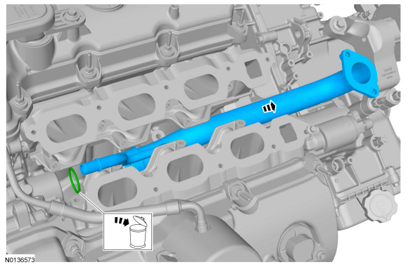
- NOTE: Do not pull the other end of the coolant tube out of the
engine block when separating the thermostat housing.
Discard the specified component. Follow local disposal regulations.

- Discard the specified component. Follow local disposal regulations.
Installation
- NOTICE: Use Motorcraft Orange Antifreeze/Coolant. Do not mix
coolant types. Mixing coolant types degrades the coolant corrosion
protection and may damage the engine or cooling system.
Install a new O-ring seal. Apply the specified lubricant to the specified component.
- Motorcraft Orange Antifreeze/Coolant.
- Install a new gasket.
- Tighten the bolts in 2 stages.
- Stage 1: Tighten to 8 Nm (72 lb-in).
- Stage 2: Tighten an additional 90 degrees.
- Tighten the bolts in 2 stages.

- Install the ACL outlet pipe. Refer to Section 303-12.
- Fill and bleed the cooling system. Refer to Cooling System Draining, Filling and Bleeding.
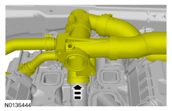
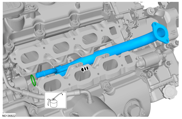
Coolant Inlet Pipe - 3.5L Ti-VCT, 3.7L Ti-VCT
Material
Removal
- Remove the lower intake manifold. For 3.5L Ti-VCT engines, refer to Section 303-01A. For 3.7L Ti-VCT engines, refer to Section 303-01D.

-
- Discard the specified component. Follow local disposal regulations.
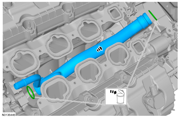
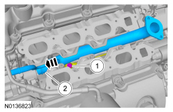
Installation
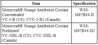
- NOTICE: Use Motorcraft Orange Antifreeze/Coolant. Do not mix
coolant types. Mixing coolant types degrades the coolant corrosion
protection and may damage the engine or cooling system.
New O-ring seals.
Apply the specified lubricant to the specified component.- Material: Motorcraft Orange Antifreeze/Coolant.
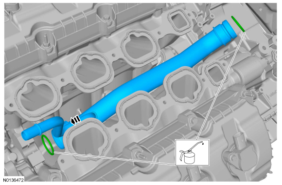

- Install the lower intake manifold. For 3.5L Ti-VCT engines, refer to Section 303-01A. For 3.7L Ti-VCT engines, refer to Section 303-01D.
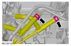
Coolant Inlet Pipe - 3.5L GTDI
Material
Removal
- With the vehicle in NEUTRAL, position it on a hoist. Refer to Section 100-02.
- Drain the cooling system. Refer to Cooling System Draining, Filling and Bleeding.
- If equipped.

- If equipped.
- Remove the fuel rails. Refer to Section 303-04B.
- Remove the battery tray. Refer to Section 414-01.


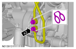
Installation
- NOTICE: Use Motorcraft Orange Antifreeze/Coolant. Use the
same type of coolant that was originally used to fill the cooling system. Do
not mix coolant types. Mixing coolant types degrades the coolant corrosion
protection and may damage the engine or cooling system.
Lubricate the new O-ring seal.
- Material: Motorcraft Orange Antifreeze/Coolant.
-
- Tighten to 20 Nm (177 lb-in).
- Use new sealing washers.
- Tighten to 40 Nm (30 lb-ft).
-
- Tighten to 10 Nm (89 lb-in).
-
- Tighten to 12 Nm (106 lb-in).
-
- Tighten to 25 Nm (18 lb-in).
- Install the battery tray. Refer to Section 414-01.
- Install the fuel rails. Refer to Section 303-04B.
- Fill and bleed the cooling system. Refer to Cooling System Draining, Filling and Bleeding in this section.
- If equipped.

- If equipped.
- Tighten to 70 Nm (52 lb-ft).

Coolant Pump - 2.0L GTDI
Material
Removal
- Drain the cooling system. Refer to Cooling System Draining, Filling and Bleeding.
- Loosen.

-
- Make sure the accessory drive belt is positioned so coolant can not contaminate the belt.
- NOTICE: Cover the A/C belt to prevent coolant contamination of
the belt.
Completely cover the A/C belt with waterproof plastic.

Installation
- NOTICE: Use Motorcraft Orange Antifreeze/Coolant. Do not mix
coolant types. Mixing coolant types degrades the coolant corrosion
protection and may damage the engine or cooling system.
Apply the specified lubricant to the specified component.
- Material: Motorcraft Orange Antifreeze/Coolant.
- Tighten to 10 Nm (89 lb-in).
-
- Finger tighten.
-
- Tighten to 20 Nm (177 lb-in).
- Fill and bleed the cooling system. Refer to Cooling System Draining, Filling and Bleeding.
Coolant Pump - 3.5L Ti-VCT, 3.7L Ti-VCT
Special Tool(s)
Material
Removal
NOTICE: During engine repair procedures, cleanliness is extremely important. Any foreign material, including any material created while cleaning gasket surfaces, that enters the oil passages, coolant passages or the oil pan can cause engine failure.
- Drain the cooling system. Refer to Cooling System Draining, Filling and Bleeding.
- Remove the engine front cover. Refer to Section 303-01A.
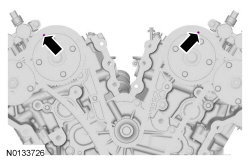
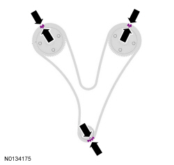
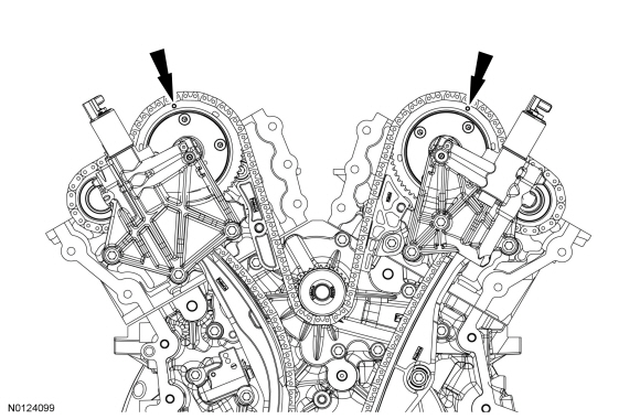
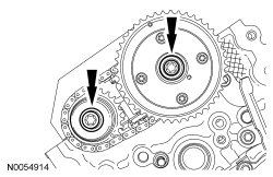
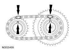
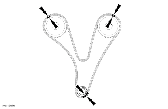
- Rotate the crankshaft clockwise and align the timing marks on the intake Variable Camshaft Timing (VCT) assemblies as shown.
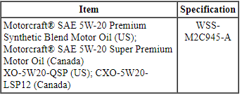
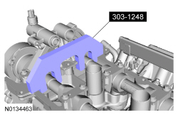
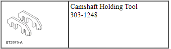
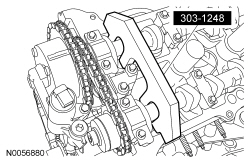
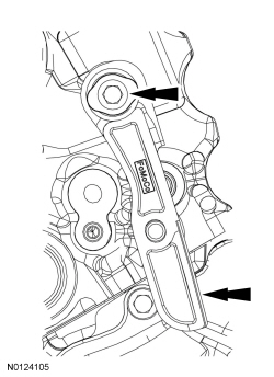
- NOTE: The Camshaft Holding Tool will hold the camshafts in the
Top Dead Center (TDC) position.
- Special tool: Tool, Camshaft Holding

- NOTE: The Camshaft Holding Tool will hold the camshafts in
the TDC position.
- Special tool: Tool, Camshaft Holding
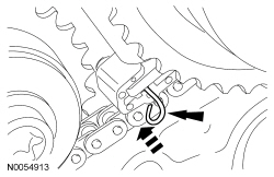
NOTE: The following 3 steps are for primary timing chains that the colored links are not visible.
- Mark the timing chain link that aligns with the timing mark on the LH intake VCT assembly as shown.
- Mark the timing chain link that aligns with the timing mark on the RH intake VCT assembly as shown.
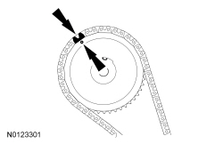
- NOTE: The crankshaft sprocket timing mark should be between the 2
colored links.
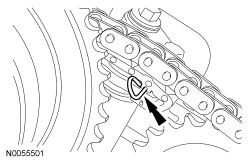
Mark the 2 timing chain links that align with the timing mark on the crankshaft sprocket as shown.

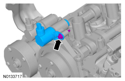
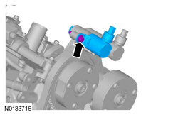
- NOTE: Removal of the VCT oil control solenoid will aid in the
removal of the primary timing chain.
NOTE: A slight twisting motion will aid in the removal of the VCT oil control solenoid.
NOTE: Keep the VCT oil control solenoid clean of dirt and debris.

- NOTE: Removal of the VCT oil control solenoid will aid in the
removal of the primary timing chain.
NOTE: A slight twisting motion will aid in the removal of the VCT oil control solenoid.
NOTE: Keep the VCT oil control solenoid clean of dirt and debris.
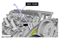
- NOTICE: Do not use power tools to remove the bolt or damage to the LH primary timing chain guide may occur.
- NOTE: The 2 VCT oil control solenoids are removed for clarity.
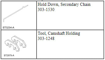
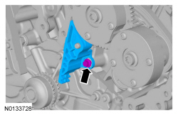
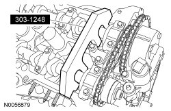
NOTE: The Hold Down, Secondary Chain is inserted through a hole in the top of the mega cap.
Compress the RH secondary timing chain tensioner and install the Hold Down, Secondary Chain in the hole on the rear of the secondary timing chain tensioner guide and let it hold against the mega cap to retain the tensioner in the collapsed position.- Special tool: Hold Down, Secondary Chain
- NOTICE: Do not use power tools to remove the bolt or damage to the RH primary timing chain guide may occur.
- Place clean lint-free shop towels in the oil pan opening to prevent coolant from entering the oil pan during coolant pump removal.
Installation
- Install 2 new gaskets.
- Tighten the bolts finger tight.
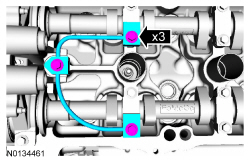
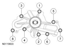
- Tighten the coolant pump bolts in the sequence shown in 2 stages.
- Stage 1: Tighten to 10 Nm (89 lb-in).
- Stage 2: Tighten an additional 45 degrees.
- Remove all of the shop towels from the oil pan opening.
- NOTICE: Any coolant that has accumulated in the oil pan must
be drained from the pan and any residual coolant cleaned from the front of
the engine and the oil pan. Failure to remove all traces of the coolant can
result in oil contamination and severe engine damage.
Remove the oil pan drain plug and allow any accumulated coolant to drain.
- Remove any residual coolant from the front of the engine and the oil pan using regulated compressed air and clean lint-free shop towels.
- Install the oil pan drain plug and tighten to 27 Nm (20 lb-ft).
-
- Tighten to 10 Nm (89 lb-in).

-
- Align the colored links with the timing marks.
- NOTE: It may be necessary to rotate the camshafts slightly, to
install the RH secondary timing assembly.
Position the 2 RH VCT assemblies and secondary timing chain onto the camshafts by aligning the holes in the VCT assemblies with the dowel pins in the camshafts.

- Install the 2 new RH VCT bolts and tighten in 4 stages.
- Stage 1: Tighten to 40 Nm (30 lb-ft).
- Stage 2: Loosen one full turn.
- Stage 3: Tighten to 25 Nm (18 lb-ft).
- Stage 4: Tighten an additional 180 degrees.
- NOTE: The 2 VCT oil control solenoids are removed for clarity.
Compress the RH secondary timing chain tensioner and remove the Hold Down, Secondary Chain.
- Make sure the secondary timing chain is centered on the timing chain tensioner guides.

-
- Tighten to 10 Nm (89 lb-in).

- NOTE: It may be necessary to rotate the camshafts slightly, to
align the timing marks.
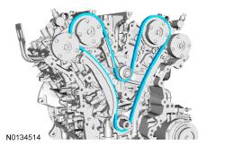
Install the primary timing chain with the colored links aligned with the timing marks on the VCT assemblies and the crankshaft sprocket.
-
- Tighten to 10 Nm (89 lb-in).

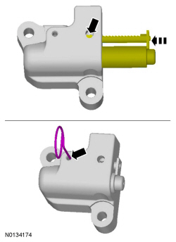
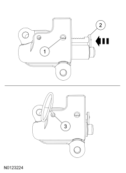
- Reset the primary timing chain tensioner.
- Release the ratchet detent.
- Using a soft-jawed vise, compress the ratchet plunger.
- Align the hole in the ratchet plunger with the hole in the tensioner housing.
- Install a lockpin.
- NOTE: It may be necessary to rotate the camshafts slightly to
remove slack from the timing chain to install the tensioner.
- Tighten to 10 Nm (89 lb-in).
- Remove the lockpin.
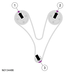
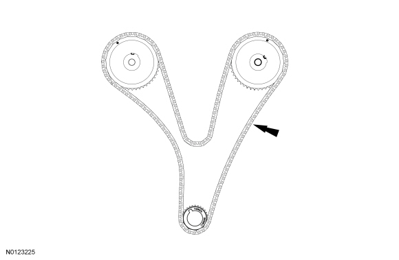
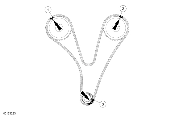
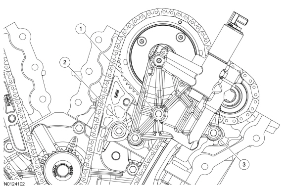
- As a post-check, verify correct alignment of all timing marks.
- There are 48 links between the RH intake VCT assembly colored link (1) and the LH intake VCT assembly colored link (2).
- There are 35 links between the LH intake VCT assembly colored link (2) and the 2 crankshaft sprocket links (3).
- NOTICE: Do not use excessive force when installing the
Variable Camshaft Timing (VCT) oil control solenoid. Damage to the mega cap
could cause the cylinder head to be inoperable. If difficult to install
the VCT oil control solenoid, inspect the bore and VCT oil control solenoid
to ensure there are no burrs, sharp edges or contaminants present on the
mating surface. Only clean the external surfaces as necessary.
NOTE: A slight twisting motion will aid in the installation of the VCT oil control solenoid.
NOTE: Keep the VCT oil control solenoid clean of dirt and debris.
- Tighten to 8 Nm (71 lb-in) then an additional 20 degrees.

- Remove the RH Tool, Camshaft Holding.

- Install the RH valve train oil tube and the 3 bolts and tighten in 2
stages.
- Stage 1: Tighten to 8 Nm (71 lb-in).
- Stage 2: Tighten an additional 45 degrees.

- Remove the LH Tool, Camshaft Holding.
- Install the LH valve train oil tube and the 3 bolts and tighten in 2
stages.
- Stage 1: Tighten to 8 Nm (71 lb-in).
- Stage 2: Tighten an additional 45 degrees.

- Install the engine front cover. Refer to Section 303-01A.
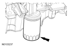
- Remove and discard the engine oil filter.
- NOTE: Lubricate the engine oil filter gasket with clean engine
oil prior to installation.
Install a new engine oil filter.
- Tighten to 5 Nm (44 lb-in) and then rotate an additional 180 degrees.
- Material: Motorcraft SAE 5W-20 Premium Synthetic Blend Motor Oil (US); Motorcraft SAE 5W-20 Super Premium Motor Oil (Canada)
- Fill and bleed the cooling system. Refer to Cooling System Draining, Filling and Bleeding.
Coolant Pump - 3.5L GTDI
Special Tool(s)
Material
Removal
NOTICE: During engine repair procedures, cleanliness is extremely important. Any foreign material, including any material created while cleaning gasket surfaces, that enters the oil passages, coolant passages or the oil pan may cause engine failure.
- With the vehicle in NEUTRAL, position it on a hoist. Refer to Section 100-02.
- Drain the cooling system. Refer to Cooling System Draining, Filling and Bleeding.
- Remove the engine front cover. Refer to Section 303-01B.
- Remove and discard the engine oil filter.
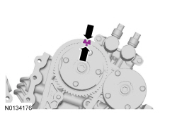
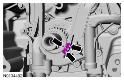
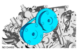
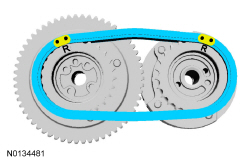
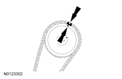
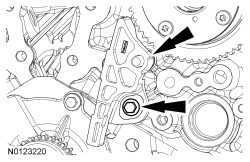
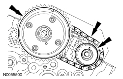
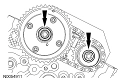
- Rotate the crankshaft clockwise and align the timing marks on the Variable Camshaft Timing (VCT) assemblies as shown.
- NOTE: The Camshaft Holding Tool will hold the camshafts in the
Top Dead Center (TDC) position.
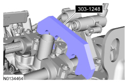
Install the Camshaft Holding Tool onto the flats of the LH camshafts.
- NOTE: The Camshaft Holding Tool will hold the camshafts in
the TDC position.
Install the Camshaft Holding Tool onto the flats of the RH camshafts.
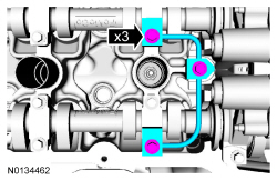
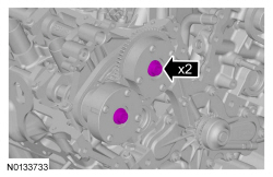
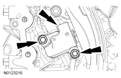
- Remove the 3 bolts and the RH VCT housing.
- Remove the 3 bolts and the LH VCT housing.
NOTE: The following 3 steps are for primary timing chains when the colored links are not visible.
- Mark the timing chain link that aligns with the timing mark on the RH intake VCT assembly as shown.
- Mark the timing chain link that aligns with the timing mark on the LH intake VCT assembly as shown.
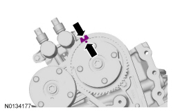
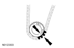
- NOTE: The crankshaft sprocket timing mark should be between the 2
colored links.
Mark the 2 timing chain links that align with the timing mark on the crankshaft sprocket as shown.
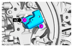
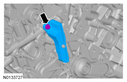
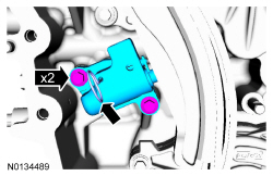
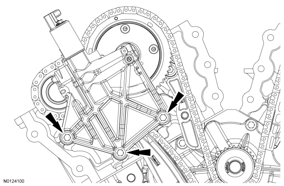
- Remove the 2 bolts and the primary timing chain tensioner.
- Remove the primary timing chain tensioner arm.
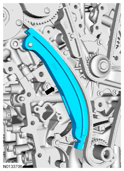
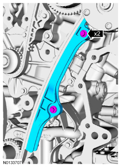
- Remove the 2 bolts and the lower LH primary timing chain guide.
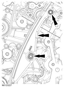
- Remove the primary timing chain.
- Remove the bolt and the upper LH primary timing chain guide.
- Compress the RH secondary timing chain tensioner and install a suitable lockpin to retain the tensioner in the collapsed position.
- NOTE: The VCT bolt and the exhaust camshaft bolt must be
discarded and new ones installed. However, the exhaust camshaft washer is
reusable.
Remove and discard the RH VCT assembly bolt and the RH exhaust camshaft sprocket bolt.
- Remove the RH VCT assembly, secondary timing chain and the RH exhaust camshaft sprocket as an assembly.
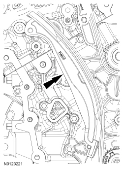
- Remove the bolt and the RH primary timing chain guide.
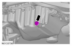
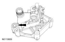
- Place clean lint-free shop towels in the oil pan opening to prevent coolant from entering the oil pan during coolant pump removal.
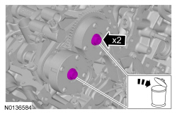
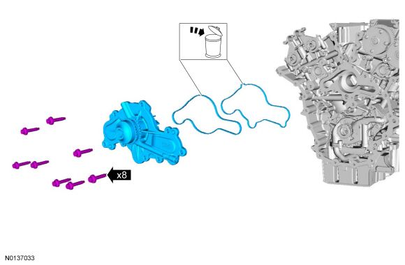
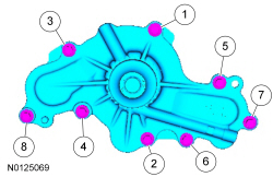
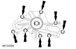
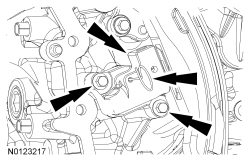
- Remove the 8 bolts and the coolant pump.
- Remove and discard the gasket.
Installation
- NOTE: Clean and inspect all sealing surfaces.
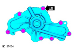
Install a new gasket, the coolant pump and the 8 bolts. Tighten in the sequence shown in 2 stages:
- Stage 1: Tighten to 10 Nm (89 lb-in).
- Stage 2: Tighten an additional 45 degrees.
- Remove all of the shop towels from the oil pan opening.
- NOTICE: Any coolant that has accumulated in the oil pan must
be drained from the pan and any residual coolant cleaned from the front of
the engine and oil pan. Failure to remove all traces of the coolant can
result in oil contamination and severe engine damage.
Remove the oil pan drain plug and allow any accumulated coolant to drain.
- Remove any residual coolant from the front of the engine and the oil pan using regulated, compressed air and clean, lint-free shop towels.
- Install the oil pan drain plug and tighten to 27 Nm (20 lb-ft).
- Install the RH primary timing chain guide and the bolt.
- Tighten to 10 Nm (89 lb-in).

- Assemble the LH VCT assembly, the LH exhaust camshaft sprocket and the
LH secondary timing chain.
- Align the colored links with the timing marks.
- Position the LH secondary timing assembly onto the camshafts.
- Install the new VCT bolt and new exhaust camshaft bolt and the original
washer. Tighten in 4 stages.
- Stage 1: Tighten to 40 Nm (30 lb-ft).
- Stage 2: Loosen one full turn.
- Stage 3: Tighten to 10 Nm (89 lb-in).
- Stage 4: Tighten 90 degrees.
- Remove the lockpin from the LH secondary timing chain tensioner.
- Install the upper LH primary timing chain guide and the bolt.
- Tighten to 10 Nm (89 lb-in).

- NOTE: The crankshaft sprocket timing mark should be between the 2
colored links.
Install the primary timing chain with the colored links aligned with the timing marks on the VCT assemblies and the crankshaft sprocket.
- Install the lower LH primary timing chain guide and the 2 bolts.
- Tighten to 10 Nm (89 lb-in).

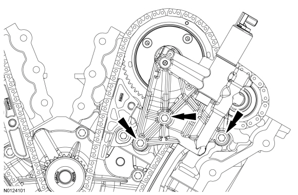
- Install the primary timing chain tensioner arm.

- Reset the primary timing chain tensioner.
- Release the ratchet detent.
- Using a soft-jawed vise, compress the ratchet plunger.
- Align the hole in the ratchet plunger with the hole in the tensioner housing and install a suitable lockpin.
- NOTE: It may be necessary to rotate the crankshaft slightly to
remove slack from the timing chain and install the tensioner.
Install the primary tensioner and the 2 bolts.
- Tighten to 10 Nm (89 lb-in).
- Remove the lockpin.
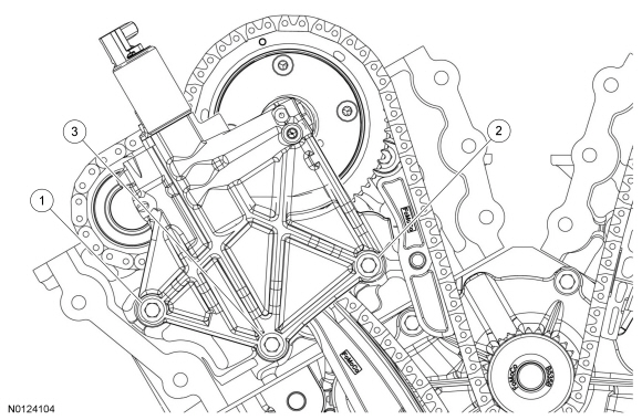
- As a post-check, verify correct alignment of all timing marks.
- There are 48 links between the RH intake VCT assembly colored link (1) and the LH intake VCT assembly colored link (2).
- There are 35 links between the LH intake VCT assembly colored link (2) and the 2 crankshaft sprockets colored links (3).
- Inspect the VCT housing seals for damage and replace if necessary.
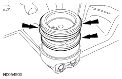
- NOTE: RH shown, LH similar.
NOTE: During removal, the O-ring seal may remain on the cylinder head. If so, remove the O-ring seal from the cylinder head, inspect the seal (replace as necessary) and install the O-ring seal on the VCT housing.
Inspect the VCT housing-to-cylinder head O-ring seals for damage and replace as necessary.
- NOTE: Make sure the dowels on the VCT housing are fully engaged
in the cylinder head prior to tightening the bolts.
Install the LH VCT housing and the 3 bolts.
- Tighten in the sequence shown to 10 Nm (89 lb-in).
- NOTE: Make sure the dowels on the VCT housing are fully engaged
in the cylinder head prior to tightening the bolts.
Install the RH VCT housing and the 3 bolts.
- Tighten in the sequence shown to 10 Nm (89 lb-in).
- NOTE: Lubricate the engine oil filter gasket with clean engine
oil prior to installing the oil filter.
Install a new engine oil filter.
- Tighten to 5 Nm (44 lb-in) and then rotate an additional 180 degrees.

- Install the engine front cover. Refer to Section 303-01B.
- Fill and bleed the cooling system. Refer to Cooling System Draining, Filling and Bleeding.
Radiator - 2.0L GTDI
Removal
NOTICE: Whenever turbocharger air intake system components are removed, always cover open ports to protect from debris. It is important that no foreign material enter the system. The turbocharger compressor vanes are susceptible to damage from even small particles. All components should be inspected and cleaned, if necessary, prior to installation or reassembly.
NOTE: Removal steps in this procedure may contain installation details.
- Drain the cooling system. Refer to Cooling System Draining, Filling and Bleeding in this section.
- Remove the cooling fan motor and shroud. Refer to Cooling Fan Motor and Shroud - 2.0L GTDI in this section.
-
- Tighten to 5 Nm (44 lb-in).
- Remove the grille shutter assembly. Refer to Section 501-02.
-
- To install, tighten to 6 Nm (53 lb-in).
-
- To install, tighten to 5 Nm (44 lb-in).
-
- To install, tighten to 6 Nm (53 lb-in).
Installation
- To install, reverse the removal procedure.
- Fill and bleed the cooling system. Refer to Cooling System Draining, Filling and Bleeding in this section.
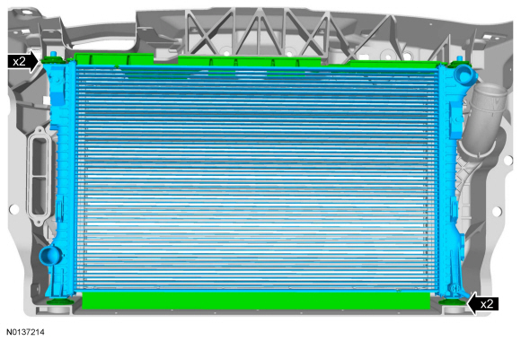
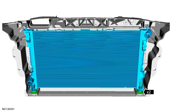
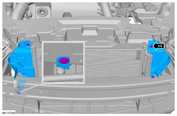
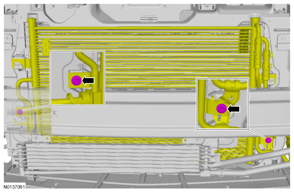
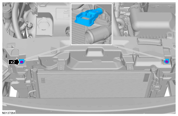
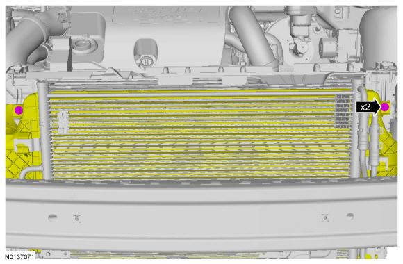
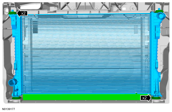
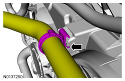
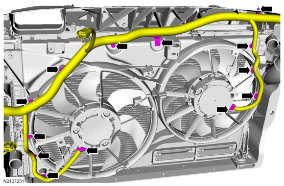
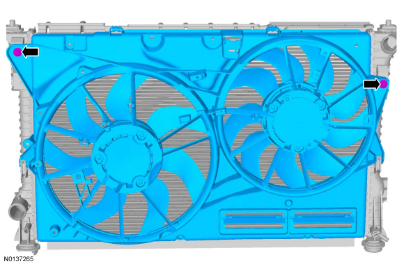
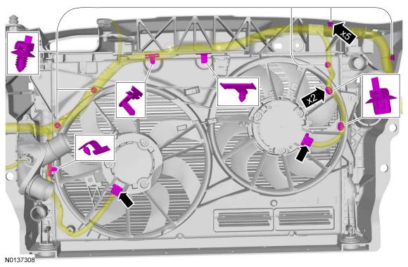
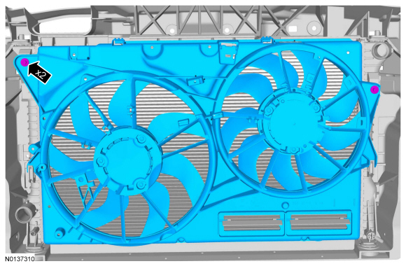
Radiator - 3.5L Ti-VCT, 3.7L Ti-VCT
Removal
NOTE: Removal steps in this procedure may contain installation details.
- Drain the cooling system. Refer to Cooling System Draining, Filling and Bleeding.
- Remove the cooling fan motor and shroud. Refer to Cooling Fan Motor and Shroud - 3.5L Ti-VCT, 3.7L Ti-VCT.
- Remove the front bumper cover. Refer to Section 501-19.
- If equipped, remove the grille shutter assembly. refer to Section 501-02.
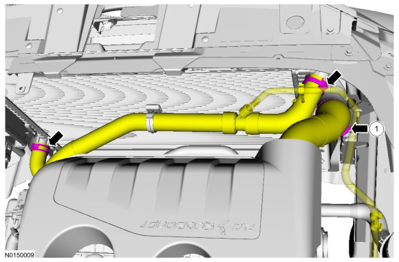
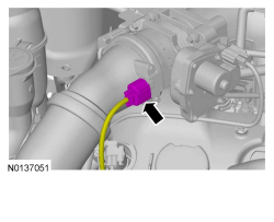
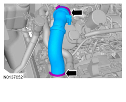
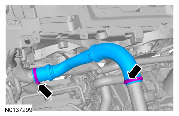
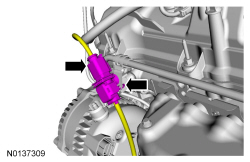
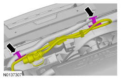
-
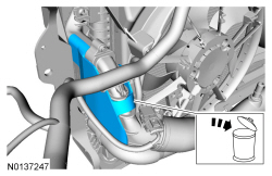
- Upper radiator hose
- Lower radiator hose
- PTU cooler hose (if equipped).
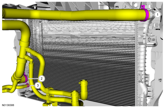
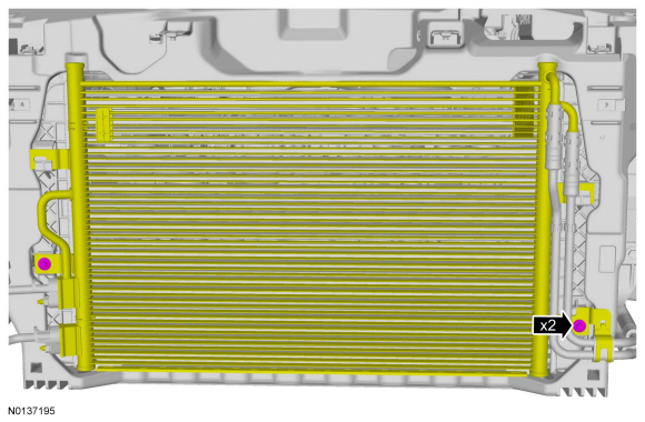
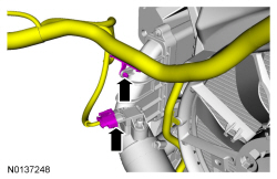
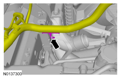
-
- To install, tighten to 5 Nm (44 lb-in).
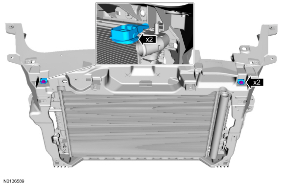
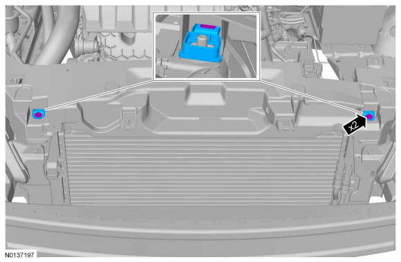
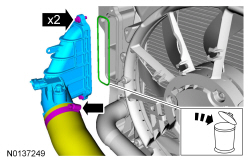
-
- To install, tighten to 6 Nm (53 lb-in).
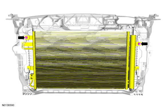
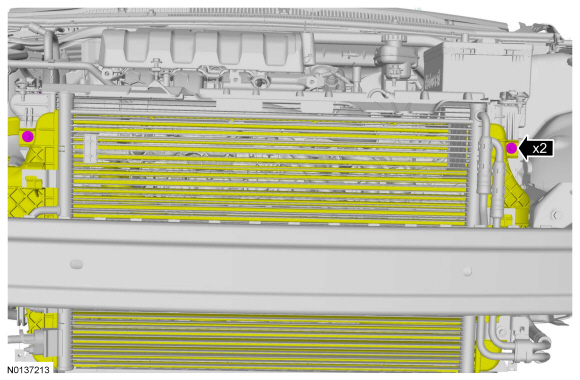
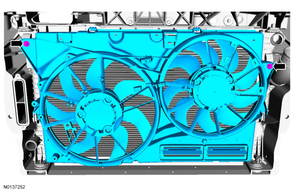
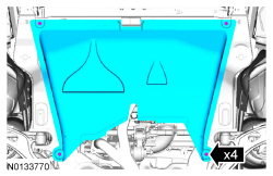
- NOTE: Make sure the bottom radiator insulators are in place when installing the radiator.
Installation
- To install, reverse the removal procedure.
- Fill and bleed the cooling system. For additional information, refer to Cooling System Draining, Filling and Bleeding.
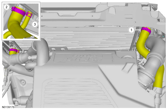
Radiator - 3.5L GTDI
Removal
NOTICE: Whenever turbocharger air intake system components are removed, always cover open ports to protect from debris. It is important that no foreign material enter the system. The turbocharger compressor vanes are susceptible to damage from even small particles. All components should be inspected and cleaned, if necessary, prior to installation or reassembly.
NOTE: Removal steps in this procedure may contain installation details.
- Drain the cooling system. Refer to Cooling System Draining, Filling and Bleeding.
- Remove the cooling fan motor and shroud. Refer to Cooling Fan Motor and Shroud - 3.5L GTDI.
- Remove the front bumper cover. Refer to Section 501-19.
- If equipped, remove the noise generator. Refer to Section 303-12.
-
- To install, tighten to 5 Nm (44 lb-in).
-
- Upper radiator hose
- Lower radiator hose
- PTU cooler hose (if equipped)
-
- To install, tighten to 6 Nm (53 lb-in).
-
- To install, tighten to 5 Nm (44 lb-in).
-
- To install, tighten to 6 Nm (53 lb-in).
- NOTE: Make sure the bottom radiator insulators are in place when installing the radiator.
Installation
- To install, reverse the removal procedure.
- Fill and bleed the cooling system. Refer to Cooling System Draining, Filling and Bleeding.
Cooling Fan Motor and Shroud - 2.0L GTDI
Removal
NOTE: Removal steps in this procedure may include installation details.
- Remove the air cleaner. For additional information, refer to Section 303-12.
- To install, tighten the hose clamp to 5 Nm (44 lb-in).
- To install, tighten the bolts to 8 Nm (71 lb-in).

-
- To install, tighten to 6 Nm (53 lb-in).
Installation
- To install, reverse the removal procedure.
- Install a new CAC adapter gasket and a new CAC adapter heat shield.
Cooling Fan Motor and Shroud - 3.5L Ti-VCT, 3.7L Ti-VCT
Removal
NOTE: Removal steps in this procedure may contain installation details.
- With the vehicle in NEUTRAL, position it on a hoist. Refer to Section 100-02.
- Remove the ACL. Refer to Section 303-12.
- If equipped.
-
- To install, tighten to 6 Nm (53 lb-in).
Installation
- To install, reverse the removal procedure.
Cooling Fan Motor and Shroud - 3.5L GTDI
Removal
NOTICE: Whenever turbocharger air intake system components are removed, always cover open ports to protect from debris. It is important that no foreign material enter the system. The turbocharger compressor vanes are susceptible to damage from even small particles. Inspect and if necessary clean all components prior to installation or reassembly.
- With the vehicle in NEUTRAL, position it on a hoist. Refer to Section 100-02.
- Remove the Air Cleaner (ACL) assembly and ACL outlet pipe. Refer to Section 303-12.

- If equipped.
- If equipped.


- If equipped.


Installation
-
- Tighten to 6 Nm (53 lb-in).

- If equipped.

- Install a new gasket.
- Finger tighten.

-
- Tighten to 8 Nm (71 lb-in).

-
- Tighten to 5 Nm (44 lb-in).

- If equipped.
- Tighten to 70 Nm (52 lb-ft).

- If equipped.

-
- Tighten to 8 Nm (71 lb-in).
-
- Tighten to 5 Nm (44 lb-in).

- Install the ACL outlet pipe and ACL assembly. For additional information, refer to Section 303-12.
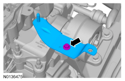
Temperature Control Valve - Transmission Fluid Warmer
Removal
NOTE: Removal steps in this procedure may contain installation details.
- Drain the cooling system. Refer to Cooling System Draining, Filling and Bleeding in this section.
-
- To install, tighten to 9 Nm (80 lb-in).
Installation
- To install, reverse the removal procedure.
- Fill and bleed the cooling system. Refer to Cooling System Draining, Filling and Bleeding in this section.
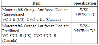
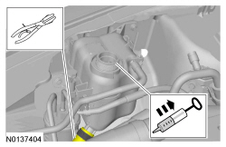
Degas Bottle
Material
Removal
NOTE: Removal steps in this procedure may contain installation details.
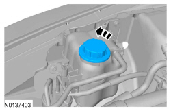
- WARNING:
Always allow the engine to cool before opening the cooling system. Do not
unscrew the coolant pressure relief cap when the engine is operating or the
cooling system is hot. The cooling system is under pressure; steam and hot
liquid can come out forcefully when the cap is loosened slightly. Failure to
follow these instructions may result in serious personal injury.
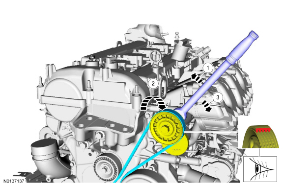
Release the pressure in the cooling system by slowly turning the pressure relief cap one-half turn counterclockwise. When the pressure is released, remove the pressure relief cap.
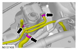
-
- To install, tighten to 9 Nm (80 lb-in).
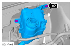
Installation
- To install, reverse the removal procedure.
- Fill the degas bottle to the top of the COLD FILL LEVEL with Motorcraft Orange Antifreeze/Coolant Prediluted.
 General Procedures
Cooling System Draining, Filling and Bleeding
Special Tool(s)
Material
Draining
With the vehicle in NEUTRAL, position it on a hoist. Refer to Section
100-02.
WARNING:
Always allo ...
 Fuel Charging and Controls - 3.5L Ti-VCT
SPECIFICATIONS
Material
Torque Specifications
DESCRIPTION AND OPERATION
Fuel Charging and Controls
Component Locations
WARNING: Do
not smoke, carry lighted tobacco or have an open flame of any type ...
Other materials:
Memory function
The memory control, located on the side seat panel, allows positioning
recall of the:
• Driver seat.
• Power mirrors.
• Adjustable pedals (if equipped).
• Power tilt/telescopic steering column (if equipped).
A. Type 1
B. Type 2
Programming a memory position
Note: You can pro ...
Parking brake
WARNING: If the parking brake is fully released, but the brake
warning lamp remains illuminated, then driving your vehicle
could result in reduced braking ability, increased stopping distances and
potential loss of brakes. See your authorized dealer as soon as possible.
WARNING: Always set the p ...
Heated and ventilated seats
Heated Seats
WARNING: Persons who are unable to feel pain to the skin
because of advanced age, chronic illness, diabetes, spinal cord
injury, medication, alcohol use, exhaustion, or other physical conditions,
must exercise care when using the seat heater. The seat heater may
cause burns even at ...
