DESCRIPTION AND OPERATION
Module Configuration
System Operation
Programmable Module Installation (PMI)
Programmable Module Installation (PMI) is a scan tool process which configures settings in a new module. Data used for the PMI process is automatically downloaded from the original module and stored when a scan tool session is started. If this data cannot be retrieved from the module being replaced, the scan tool may prompt for As-Built data entry or display a list of parameter values that need to be manually selected. Some modules are reprogrammed during PMI when a strategy/calibration update is available.
It is important that the scan tool identifies the vehicle and obtains configuration data prior to removing any modules. The new module must be able to communicate with the scan tool in order to carry out PMI.
Module Programming
Module reprogramming (also referred to as "flashing") is a scan tool process which updates the strategy/calibration in a module. Reprogramming a module with the same level of software does not improve module operation or repair a hardware failure. Module reprogramming is automatically carried out during PMI when a later strategy/calibration is available.
Limit module reprogramming to circumstances where a published TSB procedure recommends doing so. (Some modules limit the number of times it can be reprogrammed.)
A module cannot communicate with other modules on the communication network while being reprogrammed. After the reprogramming process, clear any network communication DTCs which may have been set in other modules.
Some modules are reprogrammed in coordination with other modules. Follow the IDS key cycling instructions carefully to avoid reprogramming errors, including failure of programming one or more of the modules.
Programmable Parameters
Programmable parameters are customer preference items that may be modified by the dealer via the scan tool or in some cases, modified by the customer following a procedure listed in the Owner's Literature. While many configuration options may exist for a module, only a few of these options are programmable parameters. (Some parameters must be changed in multiple modules at the same time.)
Adaptive Learning and Calibration
Some modules require a separate learning procedure be carried out if replaced as part of a repair procedure. For adaptive learning and calibration instructions, refer to the specific module removal and installation procedures.
Vehicle Identification (VID) Block
Vehicle identification block commonly stores powertrain configuration items such as VIN, tire size, axle ratio, and whether or not the vehicle is equipped with cruise control.
Transmission Identification
NOTICE: If the solenoid body identification and strategy does not match the solenoid body information in the PCM, transaxle damage or driveability concerns can occur.
The solenoid body has a unique strategy data file that must be downloaded to the PCM. There is a 7-digit solenoid body identification and a 13-digit solenoid body strategy for each solenoid body. Any time a new solenoid body is installed or the transaxle is installed, the scan tool must be used to get the solenoid body strategy data file and download it into the PCM.
If the PCM is replaced and the PCM data cannot be inhaled or exhaled, the solenoid body identification and solenoid body strategy must be downloaded into the PCM.
As-Built Data
As-Built data is a VIN -specific module configuration record. During vehicle build, the configuration from all modules is downloaded and stored in the As-Built database. As-Built data does not reflect customer preference items that have been changed from the default state. These items need to be changed using programmable parameters after the module is configured.
It is not necessary to obtain As-Built data unless directed to do so by the scan tool. This data may be accessed from the technician service publication web site.
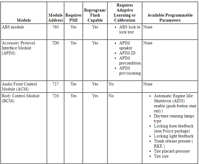
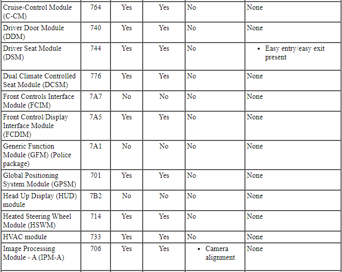
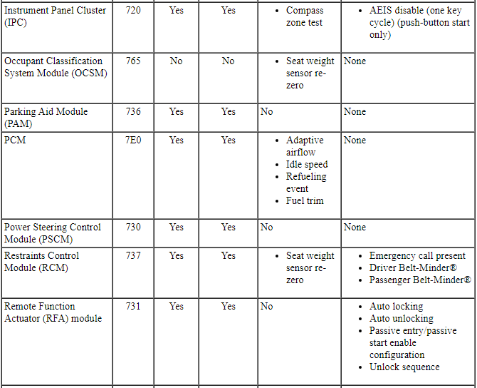
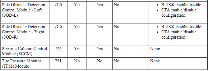
Module Configuration and Parameter Chart
The chart describes specific module configuration information:
Module Configuration and Parameter Chart
GENERAL PROCEDURES
Programmable Module Installation (PMI)
Special Tool(s)
Programmable Module Installation (PMI) Using the Integrated Diagnostic System (IDS) When the Original Module is Available
NOTE: Following module installation, some modules require a separate learning procedure be carried out. For adaptive learning and calibration instructions, refer to the specific module removal and installation procedures.
- Connect the Integrated Diagnostic System (IDS) and identify the vehicle as normal.
- From the Toolbox icon, select Module Programming and press the check mark.
- Select Programmable Module Installation.
- Select the module that is being replaced.
- Follow the on-screen instructions, turn the ignition key to the OFF position, and press the check mark.
- Install the new module and press the check mark.
- Follow the on-screen instructions, turn the ignition key to the ON position, and press the check mark.
- The IDS downloads the data into the new module and displays Module Configuration Complete.
- Test module for correct operation.
Programmable Module Installation (PMI) Using the Integrated Diagnostic System (IDS) When the Original Module is NOT Available
NOTE: Following module installation, some modules require a separate learning procedure be carried out. For adaptive learning and calibration instructions, refer to the specific module removal and installation procedures.
- Install the new module.
- Connect the IDS and identify the vehicle as normal.
- From the Toolbox icon, select Module Programming and press the check mark.
- Select Programmable Module Installation.
- Select the module that was replaced.
- Follow the on-screen instructions, turn the ignition key to the OFF position, and press the check mark.
- Follow the on-screen instructions, turn the ignition key to the ON position, and press the check mark.
- If the data is not available, the IDS displays a screen stating to contact the As-Built Data Center. Retrieve the data from the technician service publication website at this time and press the check mark.
- Enter the module data and press the check mark.
- The IDS downloads the data into the new module and displays Module Configuration Complete.
- Test module for correct operation.
 Module Communications Network
DESCRIPTION AND OPERATION
Communications Network
Overview
Multiplexing is a method of sending 2 or more signals simultaneously on the
same network circuits. Multiplexing is used to allow 2 or more el ...

Other materials:
Removal
Engine
Special Tool(s)
WARNING: Do not smoke, carry lighted tobacco or have an open flame of any
type when working on or near any fuel-related component. Highly flammable
mixtures are always present and may be ignited. Failure to follow these
instructions may result in serious personal injury.
...
Fuel quality
Note: Use of any fuel other than those recommended may cause
powertrain damage and a loss of vehicle performance; repairs may not be
covered under warranty.
Choosing the Right Fuel (Gasoline Engines)
Use only UNLEADED gasoline or UNLEADED gasoline blended with a
maximum of 15% ethanol in your g ...
Hazard warning flashers
The hazard flasher control is
located on the instrument panel
by the radio. Use it when your vehicle is disabled and is
creating a safety hazard for other motorists.
• Press the flasher control and all front and rear direction signals will
flash.
• Press the flasher control again to ...
