GENERAL PROCEDURES
Belt-Minder Deactivating/Activating
NOTE: If you are using MyKey, the Belt-Minder cannot be disabled. If the Belt-Minder has been previously disabled, it is re-enabled during the use of MyKey.
- Apply the parking brake before deactivating/activating the Belt-Minder.
- Place the gear selector lever in PARK (P).
- Place the ignition in OFF.
- Unbuckle the driver and passenger safety belts.
- Place the ignition in the ON state (do not start the engine).
- Wait until the safety belt warning indicator turns off (approximately 1 minute).
- NOTE: Step 7 and 8 must be completed within 30 seconds after
safety belt warning indictor turns off or the procedure must be repeated.
For the seating position to be disabled/enabled, buckle then unbuckle the safety belt 3 times, ending with the safety belt unbuckled. After this step, the safety belt warning indicator illuminates for 3 seconds and turns off.
- When the safety belt warning indicator turns off, buckle then unbuckle
the safety belt.
- This disables the Belt-Minder feature for that seating position, if it is currently enabled. As confirmation, the safety belt warning indicator flashes 4 times per second for 3 seconds.
- This enables the safety Belt-Minder feature for that seating position, if it is currently disabled. As confirmation, the safety belt warning indicator flashes 4 times per second for 3 seconds, followed by 3 seconds with the safety belt warning indicator off, then the safety belt warning indicator flashes 4 times per second for 3 seconds again.
- After confirmation, the deactivation/activation procedure is complete.
REMOVAL AND INSTALLATION
Instrument Panel Cluster (IPC)
NOTE: Steering column shown removed for clarity.
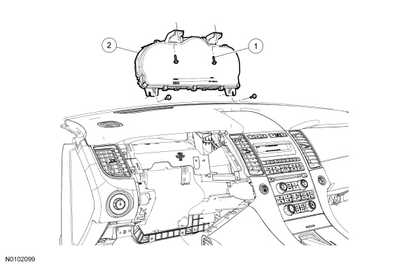
Removal
NOTE: It is critical that the correct Instrument Panel Cluster (IPC) be installed when installing a new IPC. The IPC differs between Passive Anti-Theft System (PATS) vehicles equipped with Intelligent Access (IA) and vehicles not equipped with IA. If the incorrect IPC is installed, the vehicle may exhibit a PATS no-start condition.
NOTE: If installing a new IPC, all vehicle keys are erased during the parameter reset procedure. Verify at least 2 of the vehicle keys are available prior to carrying out this procedure.
- If installing a new IPC, upload the module configuration information to the scan tool. For additional information, refer to Section 418-01.
- Remove the IPC finish panel. For additional information, refer to Section 501-12.
- Remove the 4 screws and the IPC.
- Disconnect the electrical connector.
Installation
- Position the IPC in the instrument panel, connect the electrical connector and install the 4 screws.
- Install the IPC finish panel. For additional information, refer to Section 501-12.
- If installing a new IPC, download the IPC configuration information from the scan tool into the new IPC. For additional information, refer to Programmable Module Installation (PMI) in Section 418-01.
- NOTE: If installing a new IPC on vehicles that are not equipped
with IA, the IPC and the PCM require a parameter reset to allow the IPC and
the PCM to recognize each other. Failure to carry out the parameter reset to
the IPC and the PCM may result in a no start condition.
If installing a new IPC on vehicles that are not equipped with IA, carry out the parameter reset procedure. For additional information, Refer to the appropriate section in Group 419 for the procedure..
- NOTE: If equipped, the vehicle's Integrated Keyhead
Transmitter (IKT) keys must be programmed to the new IPC.
If installing a new IPC, carry out the PATS key programming. For additional information, Refer to the appropriate section in Group 419 for the procedure..
Instrument Panel Cluster (IPC) Lens
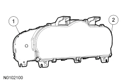
Removal and Installation
- Remove the IPC. For additional information, refer to Instrument Panel Cluster (IPC) in this section.
- Release the 6 retaining tabs and remove the IPC lens.
- To install, reverse the removal procedure.
 Diagnosis and Testing
Instrumentation, Message Center and Warning Chimes
Special Tool(s)
DTC Chart(s)
Diagnostics in this manual assume a certain skill level and knowledge of
Ford-specific diagnostic practices. REFER to& ...
 Horn
Horn
SPECIFICATIONS
Torque Specifications
DESCRIPTION AND OPERATION
Horn
Component Location
Overview
The horn emits an audible tone when the driver air bag module is pressed. The
horn output is control ...
Other materials:
Diagnosis and Testing
Airbag and Safety Belt Pretensioner Supplemental Restraint System (SRS)
DTC Charts
The DTCs can be retrieved from the RCM and the OCSM with a scan tool via
the DLC.
Restraints Control Module (RCM) DTC ChartNOTE: Always make sure the correct SRS component is b ...
Opening and closing the hood
1. Inside the vehicle, pull the hood
release handle located under the
bottom of the instrument panel near
the steering column.
2. Go to the front of the vehicle and
release the auxiliary latch that is
located under the front center of
the hood.
3. Lift the hood. ...
Removal and Installation
Hood Latch
Removal and Installation
Remove the upper radiator sight shield.
Remove the 8 screws.
Remove the 4 bolts.
Remove the 2 pin-type retainers.
NOTE: Mark the position of the hood latch prior to removing the
hood latch bolts.Remove the 2 bolts and position t ...
