
SPECIFICATIONS
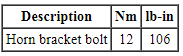
Torque Specifications
DESCRIPTION AND OPERATION
Horn
Component Location
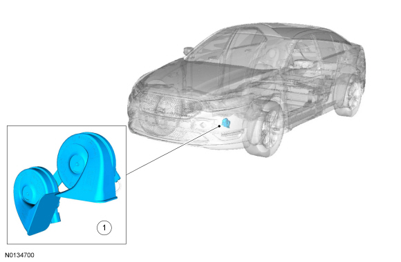

Overview
The horn emits an audible tone when the driver air bag module is pressed. The horn output is controlled by a relay, which is integral to the BCM.
System Operation
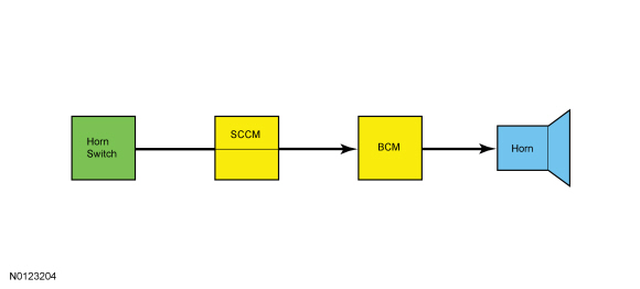
System Diagram
Horn Operation
The horn switch consists of 2 sets of contacts separated by springs. The lower set is connected to ground and the upper set is connected to the horn signal circuit.
When the driver air bag module is pressed, it pushes down on the upper set of contacts, collapsing the springs and allowing the contacts to touch. When the contacts touch, it completes the circuit and provides the ground signal which is routed through the clockspring, the SCCM and then to the horn relay, which is integral to the BCM.
The BCM supplies the control and switched (load) voltage to the horn relay. When energized, the horn relay provides voltage to the horn, enabling the horn to sound.
DIAGNOSIS AND TESTING
Horn
Symptom Chart
Diagnostics in this manual assume a certain skill level and knowledge of Ford-specific diagnostic practices. Refer to Diagnostic Methods in Section 100-00 for information about these practices.

Pinpoint Tests
Pinpoint Test A: The Horn Is Inoperative
Diagnostic Overview
Diagnostics in this manual assume a certain skill level and knowledge of Ford-specific diagnostic practices. Refer to Diagnostic Methods in Section 100-00 for information about these practices.
Normal Operation and Fault Conditions
REFER to Horn.
-
Possible Sources
- Fuse
- Wiring, terminals or connectors
- Steering wheel harness
- Horn
- Clockspring
- Horn switch (part of the steering wheel)
- BCM
- SCCM
Visual Inspection and Diagnostic Pre-checks
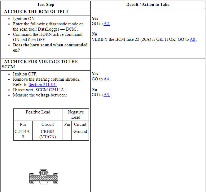
Inspect the BCM fuse 22 (20A).
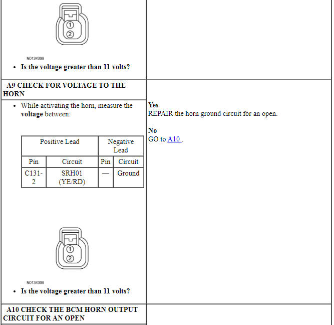
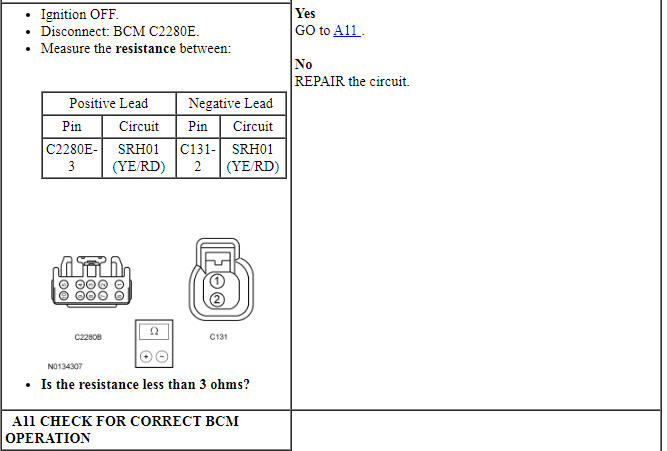
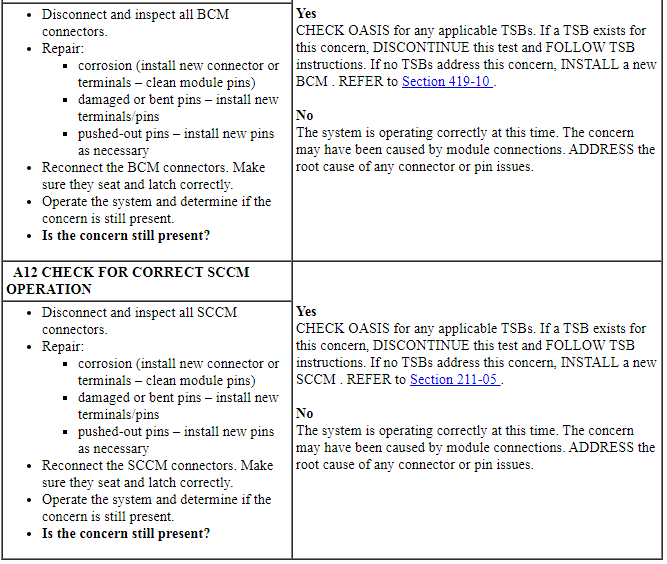
PINPOINT TEST A: THE HORN IS INOPERATIVE
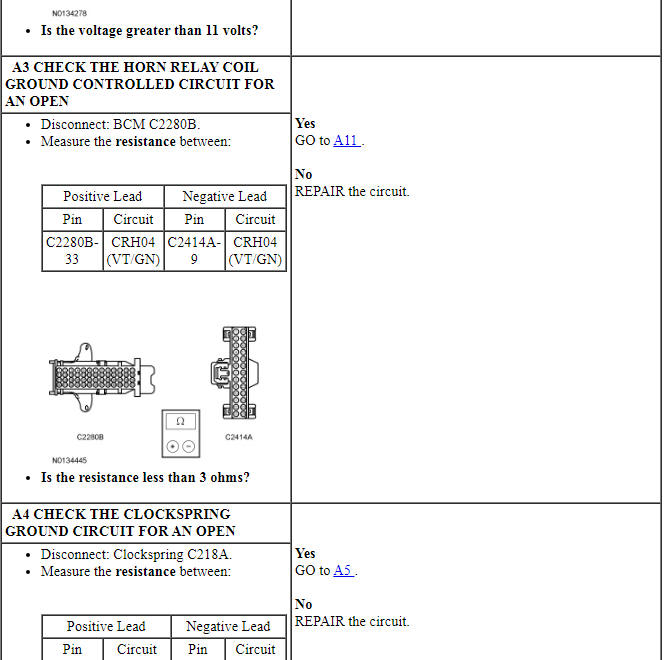
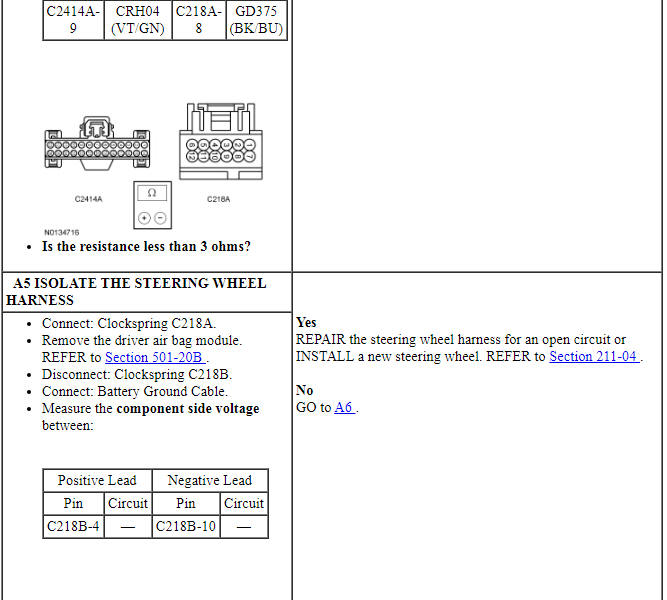
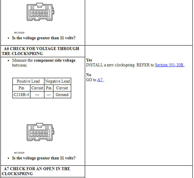
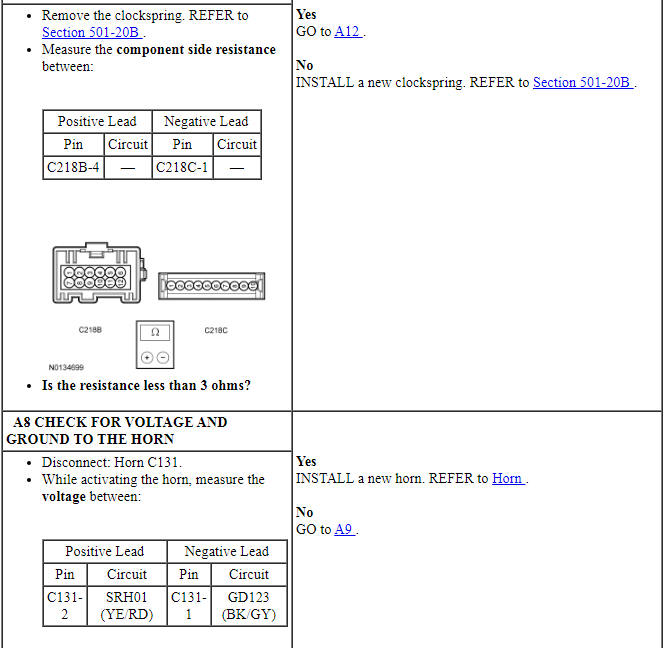
Pinpoint Test B: The Horn Is Always On
Diagnostic Overview
Diagnostics in this manual assume a certain skill level and knowledge of Ford-specific diagnostic practices. Refer to Diagnostic Methods in Section 100-00 for information about these practices.
Normal Operation and Fault Conditions
REFER to Horn.
-
Possible Sources
- Wiring, terminals or connectors
- Steering wheel harness
- Clockspring
- Horn switch (part of the steering wheel)
- BCM
- SCCM
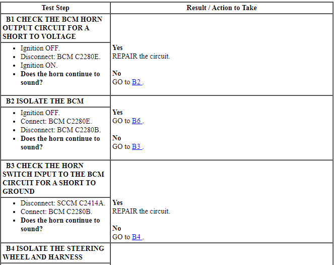
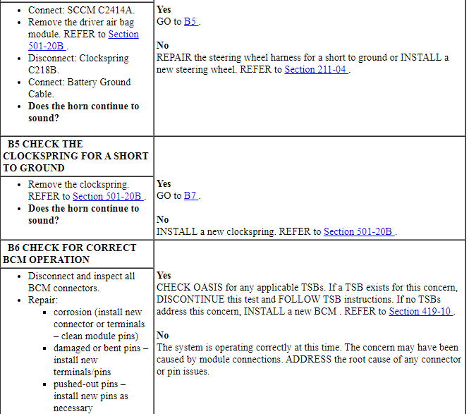
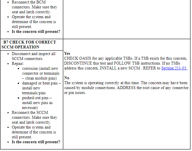
PINPOINT TEST B: THE HORN IS ALWAYS ON
REMOVAL AND INSTALLATION
Horn
Removal and Installation
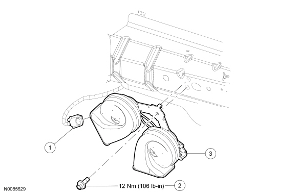
- With the vehicle in NEUTRAL, position it on a hoist. For additional information, refer to Section 100-02.
- NOTE: The horn and bracket are installed as an assembly.
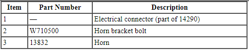
Remove the bolt and the horn.
- Disconnect the electrical connector.
- To install, tighten to 12 Nm (106 lb-in).
- To install, reverse the removal procedure.
 General Procedures, Removal and Installation
GENERAL PROCEDURES
Belt-Minder Deactivating/Activating
NOTE: If you are using MyKey, the Belt-Minder cannot be disabled. If
the Belt-Minder has been previously disabled, it is re-enabled during ...
 Parking Aid - Audible
SPECIFICATIONS
General Specifications
DESCRIPTION AND OPERATION
Parking Aid
Component Location
Parking aid speaker
PAM
Parking aid sensors
Overview
The parking aid system sounds a warning to al ...
Other materials:
Parking brake
WARNING: If the parking brake is fully released, but the brake
warning lamp remains illuminated, then driving your vehicle
could result in reduced braking ability, increased stopping distances and
potential loss of brakes. See your authorized dealer as soon as possible.
WARNING: Always set the p ...
Moonroof
WARNING: Do not let children play with the moonroof or leave
children unattended in the vehicle. They may seriously hurt
themselves.
WARNING: When closing the moonroof, you should verify that it
is free of obstructions and ensure that children and/or pets are
not in the proximity of the moonroo ...
Pedals
Adjustable pedals
WARNING: Never adjust the accelerator and brake pedal with
feet on the pedals while the vehicle is moving.
The control is located on the left side of the steering column. Press and
hold the appropriate control to move the pedals.
A. Farther
B. Closer
The pedal positions ar ...
