Upper Intake Manifold
Removal
NOTICE: If the engine is repaired or replaced because of upper engine failure, typically including valve or piston damage, check the intake manifold for metal debris. If metal debris is found, install a new intake manifold. Failure to follow these instructions can result in engine damage.
- Remove theAir Cleaner (ACL) outlet pipe. For additional information, refer to Section 303-12.
- Disconnect the Evaporative Emission (EVAP) canister vent solenoid and
throttle body electrical connectors.
- Detach the wiring harness pin-type retainer from the upper intake manifold.

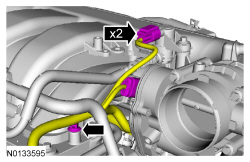
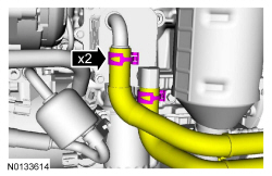
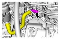
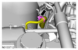
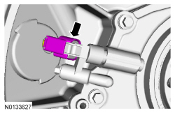
- Disconnect the EVAP vapor tube from the EVAP canister vent solenoid. For
additional information, refer to Section 310-00.
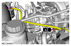
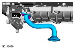
- Detach the EVAP vapor tube from the 2 retainers.

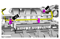
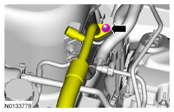
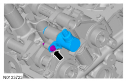
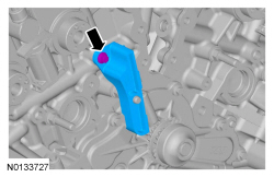
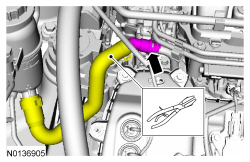
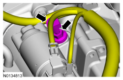
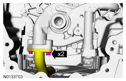
- Release the clamps and disconnect the power brake booster vacuum supply hose and crankcase ventilation hose from the upper intake manifold.
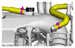
- Detach the 2 coolant tube retainers from the upper intake manifold.
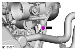
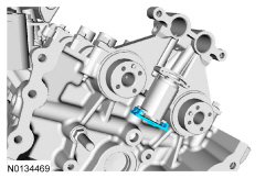
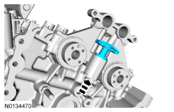
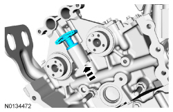
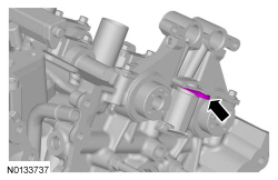
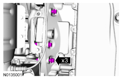
- Remove the upper intake manifold support bracket bolt.
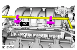
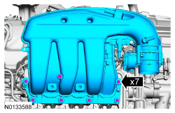
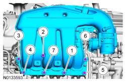
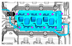
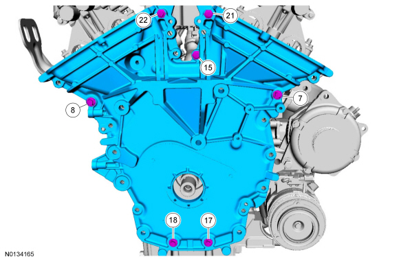
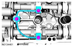
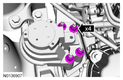
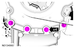
- Remove the 7 bolts and the upper intake manifold.
- Remove and discard the gasket.
- Clean and inspect all of the sealing surfaces of the upper and lower intake manifold.
Installation
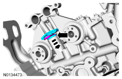
- Using a new gasket, install the upper intake manifold and the 7 bolts.
- Tighten in the sequence shown in 2 stages.
- Stage 1: Tighten to 10 Nm (89 lb-in).
- Stage 2: Tighten an additional 45 degrees.
- Tighten in the sequence shown in 2 stages.
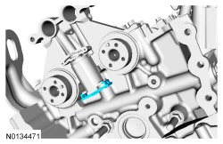
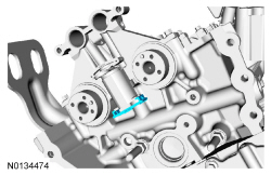
- Install the upper intake manifold support bracket bolt.
- Tighten to 10 Nm (89 lb-in).

- Attach the 2 coolant tube retainers to the upper intake manifold.

- Connect the power brake booster vacuum supply hose and crankcase ventilation hose to the upper intake manifold.

- Connect the EVAP vapor tube to the EVAP canister vent solenoid. For
additional information, refer to Section 310-00.
- Attach the EVAP vapor tube to the 2 retainers.
- Connect the EVAP canister vent solenoid and throttle body electrical
connectors.
- Attach the wiring harness pin-type retainer to the upper intake manifold.
- Install the ACL outlet pipe. For additional information, refer to Section 303-12.
Lower Intake Manifold
Removal
NOTICE: During engine repair procedures, cleanliness is extremely important. Any foreign material, including any material created while cleaning gasket surfaces that enters the oil passages, coolant passages or the oil pan, can cause engine failure.
NOTE: It is not necessary to remove the fuel rail from the intake manifold assembly.
- With the vehicle in NEUTRAL, position it on a hoist. For additional information, refer to Section 100-02.
- Release the fuel system pressure. For additional information, refer to Section 310-00.
- Disconnect the battery ground cable. For additional information, refer to Section 414-01.
- Drain the cooling system. For additional information, refer to Section 303-03.
- Remove the upper intake manifold. For additional information, refer to Upper Intake Manifold in this section.
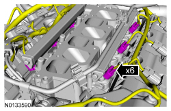
- Disconnect the 6 fuel injector electrical connectors.
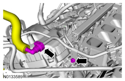
- Disconnect the fuel supply tube-to-fuel rail quick connect coupling. For
additional information, refer to the quick connect coupling procedure
in Section 310-00.
- Remove the fuel supply tube-to-engine front cover bolt.

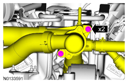
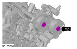
- Remove the 2 thermostat housing-to-lower intake manifold bolts.

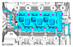
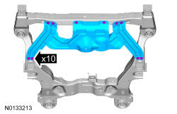
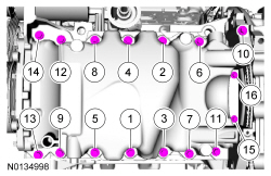
- Remove the 10 bolts and the lower intake manifold.
- Remove and discard the intake manifold and thermostat housing gaskets.
- Clean and inspect all sealing surfaces.
Installation
- NOTICE: If the engine is repaired or replaced because of upper
engine failure, typically including valve or piston damage, check the intake
manifold for metal debris. If metal debris is found, install a new intake
manifold. Failure to follow these instructions can result in engine damage.
Using new lower intake manifold and thermostat housing gaskets, install the lower intake manifold and the 10 bolts.
- Tighten in the sequence shown to 10 Nm (89 lb-in).
- Install the 2 thermostat housing-to-lower intake manifold bolts.
- Tighten to 10 Nm (89 lb-in).
- Connect the fuel supply tube-to-fuel rail quick connect coupling. For
additional information, refer to the quick connect coupling procedure
in Section 310-00.
- Install the fuel supply tube-to-engine front cover bolt and tighten to 10 Nm (89 lb-in).
- Connect the 6 fuel injector electrical connectors.

- Install the upper intake manifold. For additional information, refer to Upper Intake Manifold in this section.
- Connect the battery ground cable. For additional information, refer to Section 414-01.
- Fill and bleed the cooling system. For additional information, refer to Section 303-03.
Valve Cover - LH
Material
Removal
NOTICE: During engine repair procedures, cleanliness is extremely important. Any foreign material, including any material created while cleaning gasket surfaces that enters the oil passages, coolant passages or the oil pan, can cause engine failure.
NOTE: Installation of new spark plug seals or Variable Camshaft Timing (VCT) seals is only required if seals are damaged.
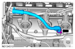
- Remove the crankcase vent tube. For additional information, refer to the quick connect coupling in Section 310-00.
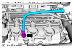
- NOTE: When removing the ignition coil-on-plugs, a slight twisting
motion will break the seal and ease removal.
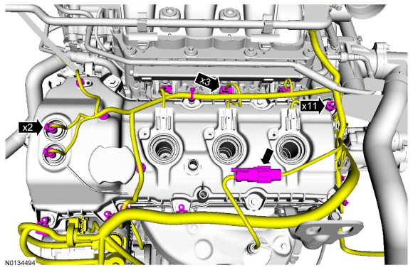
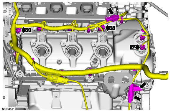
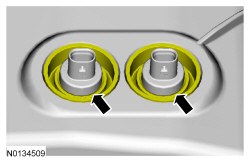
Disconnect the 3 LH coil-on-plug electrical connectors and remove the 3 bolts and the 3 LH-coil-on-plugs.
- Inspect the coil seals for rips, nicks or tears. Remove and discard any damaged coil seals.
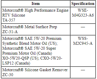
- Remove the oil level indicator.
- Remove the 2 ground wire bolts from the engine front cover and the RH strut tower.
- Remove the engine wiring harness from the LH valve cover.
- Disconnect the 2 Variable Camshaft Timing (VCT) oil control solenoid electrical connectors.
- Detach and disconnect the LH Heated Oxygen Sensor (HO2S) electrical connector.
- Disconnect the 3 fuel injector electrical connectors.
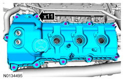
- Detach the 11 wiring harness retainers from the LH valve cover and stud bolts and position the harness aside.

- NOTICE: While removing the valve cover do not apply excessive
force to the Variable Camshaft Timing (VCT) oil control solenoid or damage
may occur.
NOTICE: If the Variable Camshaft Timing (VCT) oil control solenoid sticks to the VCT seal, carefully wiggle the valve cover until the bond breaks free or damage to the VCT seal and VCT oil control solenoid may occur.
Loosen the 4 bolts and 7 stud bolts.- Remove the valve cover.
- Discard the gasket.
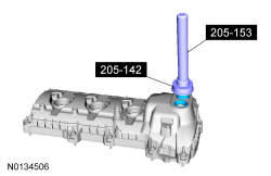
- Inspect the VCT solenoid seals. Remove any damaged seals.
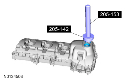
- Using the Differential Bearing Cone Installer and Handle, remove and discard the seal(s).
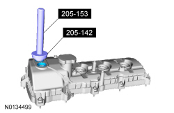
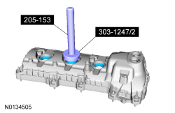
- Inspect the spark plug tube seals. Remove any damaged seals.
- Using the Spark Plug Tube Seal Remover and Handle, remove and discard the seal(s).
- Clean the valve cover, cylinder head and engine front cover sealing surfaces with metal surface prep.
Installation
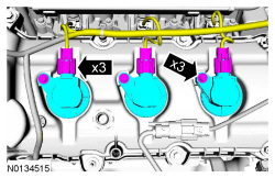
- NOTE: Installation of new seals is only required if damaged seals
were removed.
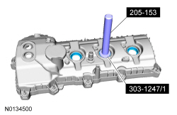
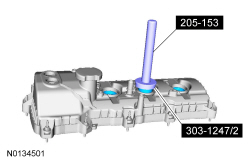
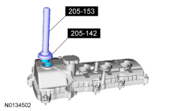
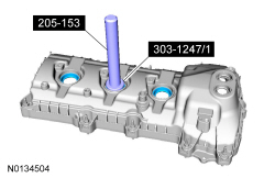
Using the VCT Spark Plug Tube Seal Installer and Handle, install new spark plug tube seals.
- NOTE: Installation of new seals is only required if damaged seals
were removed.
Using the Differential Bearing Cone Installer and Handle, install new VCT solenoid seal(s).
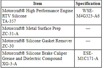
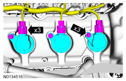
- NOTICE: Failure to use Motorcraft High Performance Engine RTV
Silicone may cause the engine oil to foam excessively and result in serious
engine damage.
NOTE: If the valve cover is not installed and the fasteners tightened within 4 minutes, the sealant must be removed and the sealing area cleaned. To clean the sealing area, use silicone gasket remover and metal surface prep. Failure to follow this procedure can cause future oil leakage.
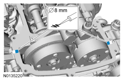
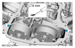
Apply an 8 mm (0.31 in) bead of Motorcraft High Performance Engine RTV Silicone to the engine front cover-to-LH cylinder head joints.
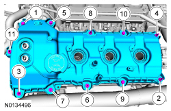
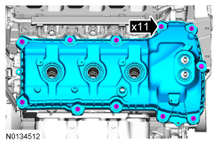
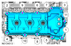
- Using a new gasket, install the LH valve cover and tighten the 4 bolts
and 7 stud bolts.
- Tighten in the sequence shown to 10 Nm (89 lb-in).
- Make sure the VCT seals in the valve cover are below the top of the VCT oil control solenoid electrical connector or the VCT seal may leak oil.

- Install the engine wiring harness to the LH valve cover.
- Position the wiring harness and attach the 11 wiring harness retainers to the LH valve cover and stud bolts.
- Connect the 3 fuel injector electrical connectors.
- Connect and attach the LH HO2S electrical connector.
- Connect the 2 VCT oil control solenoid electrical connectors.
- Position the ground wires to the engine front cover and the RH strut
tower and install the 2 bolts.
- Tighten to 10 Nm (89 lb-in).

- Install the oil level indicator.

- NOTE: Apply a small amount of dielectric grease to the inside of
the ignition coil-on-plug boots before attaching to the spark plugs.
Install the 3 LH -coil-on-plugs and the 3 bolts.
- Tighten to 7 Nm (62 lb-in.
- Connect the 3 coil-on-plug electrical connectors.

- Install the crankcase vent tube. For additional information, refer to the quick connect coupling in Section 310-00.

Valve Cover - RH
Material
Removal
NOTICE: During engine repair procedures, cleanliness is extremely important. Any foreign material, including any material created while cleaning gasket surfaces that enters the oil passages, coolant passages or the oil pan, can cause engine failure.
NOTE: Installation of new spark plug seals or Variable Camshaft Timing (VCT) seals is only required if seals are damaged.
- Remove the upper intake manifold. For additional information, refer to Upper Intake Manifold.
- NOTE: When removing the ignition coil-on-plugs, a slight twisting
motion will break the seal and ease removal.
Disconnect the 3 RH coil-on-plug electrical connectors and remove the 3 bolts and the 3 RH coil-on-plugs.
- Inspect the coil seals for rips, nicks or tears. Remove and discard any damaged coil seals.
- Remove the PCV crankcase vent tube.
- Remove the engine wiring harness from the RH valve cover.
- Disconnect the 2 Variable Camshaft Timing (VCT) oil control solenoid electrical connectors.
- Detach and disconnect the RH Catalyst Monitor Sensor (CMS) electrical connector.
- Disconnect the 3 fuel injector electrical connectors.
- Disconnect the Cylinder Head Temperature (CHT) sensor wiring harness jumper electrical connector.
- Detach the 9 wiring harness retainers from the RH valve cover and stud bolts and position the harness aside.
- NOTICE: While removing the valve cover do not apply excessive
force to the Variable Camshaft Timing (VCT) oil control solenoid or damage
may occur.
NOTICE: If the Variable Camshaft Timing (VCT) oil control solenoid sticks to the VCT seal, carefully wiggle the valve cover until the bond breaks free or damage to the VCT seal and VCT oil control solenoid may occur.
Loosen the 2 bolts and 9 stud bolts.- Remove the valve cover.
- Discard the gasket.
- Inspect the 2 VCT solenoid seals. Remove any damaged seals.
- Using the Differential Bearing Cone Installer and Handle, remove the seal(s).
- Inspect the spark plug tube seals. Remove any damaged seals.
- Using the VCT Spark Plug Tube Seal Remover and Handle, remove the seal(s).
- Clean the valve cover, cylinder head and engine front cover sealing surfaces with metal surface prep.
Installation
- NOTE: Installation of new seals is only required if damaged seals
were removed.
Using the VCT Spark Plug Tube Seal Installer and Handle, install new spark plug tube seals.
- NOTE: Installation of new seals is only required if damaged seals
were removed.
Using the Differential Bearing Cone Installer and Handle, install new VCT solenoid seal(s).
- NOTICE: Failure to use the correct Motorcraft High
Performance Engine RTV Silicone may cause the engine oil to foam excessively
and result in serious engine damage.
NOTE: If the valve cover is not installed and the fasteners tightened within 4 minutes, the sealant must be removed and the sealing area cleaned. To clean the sealing area, use silicone gasket remover and metal surface prep. Failure to follow this procedure can cause future oil leakage.
Apply an 8 mm (0.31 in) bead of Motorcraft High Performance Engine RTV Silicone to the engine front cover-to-RH cylinder head joints.
- Using a new gasket, install the RH valve cover and tighten the 2 bolts
and 9 stud bolts.
- Tighten in the sequence shown to 10 Nm (89 lb-in).
- Make sure the VCT seals in the valve cover are below the top of the VCT oil control solenoid electrical connector or the VCT seal may leak oil.
- Install the engine wiring harness to the RH valve cover.
- Position the wiring harness and attach the 9 wiring harness retainers to the RH valve cover and stud bolts.
- Connect the CHT sensor wiring harness jumper electrical connector.
- Connect the 3 fuel injector electrical connectors.
- Connect and attach the RH CMS electrical connector.
- Connect the 2 VCT oil control solenoid electrical connectors.

- Install the PCV crankcase vent tube.

- NOTE: Apply a small amount of dielectric grease to the inside of
the ignition coil-on-plug boots before attaching to the spark plugs.
Install the 3 RH coil-on-plugs and the 3 bolts.
- Tighten to 7 Nm (62 lb-in).
- Connect the 3 coil-on-plug electrical connectors.

- Install the upper intake manifold. For additional information, refer to Upper Intake Manifold.
Crankshaft Pulley
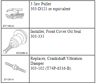
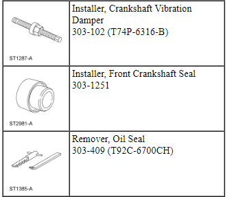
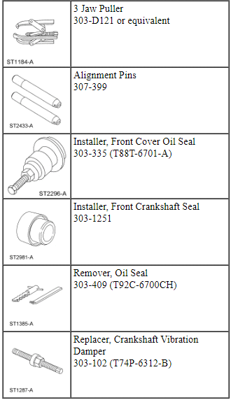
Special Tool(s)
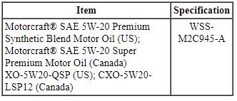
Material
Removal
- With the vehicle in NEUTRAL, position it on a hoist. For additional information, refer to Section 100-02.
- Remove the accessory drive belt. For additional information, refer to Section 303-05.
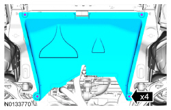
- If equipped, release the 4 retainers and remove the underbody shield.

- If equipped, remove the 10 retainers and the skid plate.

- Remove the 4 accessory drive shield scrivets.
- Remove the fender splash shield. For additional information, refer to Section 501-02.
- Remove the crankshaft pulley bolt and washer.
- Discard the bolt.
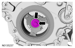
- Using the 3 Jaw Puller, remove the crankshaft pulley.
Installation
- Lubricate the crankshaft front seal inner lip with clean engine oil.
- NOTE: Lubricate the outside diameter sealing surfaces with clean
engine oil.
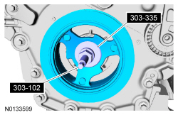
Using the Front Cover Oil Seal Installer and Crankshaft Vibration Damper Replacer, install the crankshaft pulley.

- Using the strap wrench, install the crankshaft pulley washer and new
bolt and tighten in 4 stages.
- Stage 1: Tighten to 120 Nm (89 lb-ft).
- Stage 2: Loosen one full turn.
- Stage 3: Tighten to 50 Nm (37 lb-ft).
- Stage 4: Tighten an additional 90 degrees.

- Install the fender splash shield. For additional information, refer to Section 501-02.
- Install the 4 accessory drive shield scrivets.

- Install the accessory drive belt. For additional information, refer to Section 303-05.
- If equipped, install the skid plate and the 10 retainers.
- Tighten to 70 Nm (52 lb-ft).

- If equipped, install the underbody shield and attach the 4 retainers.

- After completing the repairs, use the scan tool to perform the Misfire Monitor Neutral Profile Correction procedure following the on-screen instructions.
Crankshaft Front Seal
Special Tool(s)

Material
Removal
- With the vehicle in NEUTRAL, position it on a hoist. For additional information, refer to Section 100-02.
- Remove the crankshaft pulley. For additional information, refer to Crankshaft Pulley in this section.
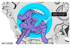
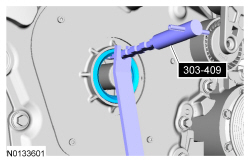
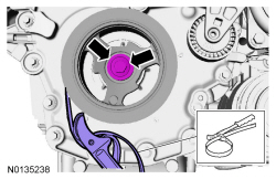
- Using the Oil Seal Remover, remove and discard the crankshaft front
seal.
- Clean all sealing surfaces with metal surface prep.

Installation
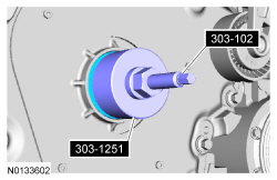
- NOTE: Apply clean engine oil to the crankshaft front seal bore in
the engine front cover.
Using the Front Crankshaft Seal Installer and Crankshaft Vibration Damper Installer, install a new crankshaft front seal.
- Install the crankshaft pulley. For additional information, refer to Crankshaft Pulley in this section.
Flexplate
Removal
- With the vehicle in NEUTRAL, position it on a hoist. For additional information, refer to Section 100-02.
- Remove the transaxle. For additional information, refer to Section 307-01A.
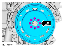
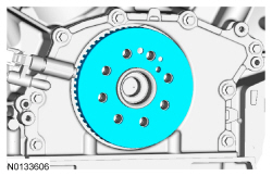
- Remove the 8 bolts and the flexplate.
Installation
- NOTE: One of the 8 flexplate holes are offset so the flexplate
can only be installed in one position.
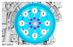
Install the flexplate and the 8 bolts.
- Tighten in the sequence shown to 80 Nm (59 lb-ft).
- Install the transaxle. For additional information, refer to Section 307-01A.
- After completing the repairs, use the scan tool to perform the Misfire Monitor Neutral Profile Correction procedure following the on-screen instructions.
Engine Front Cover
Special Tool(s)
Material
Removal
NOTICE: During engine repair procedures, cleanliness is extremely important. Place clean, lint-free shop towels over exposed engine cavities. Carefully remove the towels so foreign material is not dropped into the engine. Any foreign material (including any material created while cleaning gasket surfaces) that enters the oil passages or the oil pan, may cause engine failure.
- With the vehicle in NEUTRAL, position it on a hoist. For additional information, refer to Section 100-02.
- Recover the A/C system. For additional information, refer to Section 412-00.
- Release the fuel system pressure. For additional information, refer to Section 310-00.
- Disconnect the battery ground cable. For additional information, refer to Section 414-01.
- Remove the accessory drive belt and the tensioner. For additional information, refer to Section 303-05.
- If equipped, release the 4 retainers and remove the underbody shield.

- If equipped, remove the 10 retainers and the skid plate.

- Drain the cooling system. For additional information, refer to Section 303-03.
- Using hose clamp pliers, pinch the lower degas bottle hose and remove the hose from the coolant inlet pipe.

- Remove the degas bottle. For additional information, refer to Section 303-03.
- Remove the nut and disconnect the A/C tube.
- Discard the O-ring seal and gasket seal.
- Disconnect the fuel supply tube from the fuel rail supply tube. For
additional information, refer to Section 310-00.
- Remove the fuel tube-to-engine front cover bolt.

- Remove the LH and RH valve covers. For additional information, refer to Valve Cover - LH and Valve Cover - RH in this section.
- Remove the generator nut and stud.
- Loosen the bolt and position the generator aside.

- Remove the RH front wheel and tire. For additional information, refer to Section 204-04.
- Remove the 3 lower rubber shield scrivets from the subframe.

- Remove the RH inner fender splash shield. For additional information, refer to Section 501-02.
- Remove the crankshaft pulley bolt and washer.
- Discard the bolt.

- Using the 3 Jaw Puller, remove the crankshaft pulley.

- Using the Oil Seal Remover, remove and discard the crankshaft front seal.
- Remove the drain plug and drain the engine oil.
- Install the drain plug and tighten to 27 Nm (20 lb-ft).

- NOTICE: Failure to position the wood block and floor jack as
illustrated can result in damage to the oil pan.
Position a floor jack with a block of wood under the front of the oil pan.

- Remove the 4 engine mount nuts.

- Remove the 3 bolts and the engine mount.
- NOTICE: Do not allow the A/C compressor to contact the
subframe. Failure to follow this direction may result in damage to the A/C
compressor.
Using the floor jack, lower the engine to access the lower engine front cover bolt.
- Remove the lower M10 engine front cover bolt.

- Using the floor jack, raise the engine.
- Remove the 2 M10 engine front cover bolts.

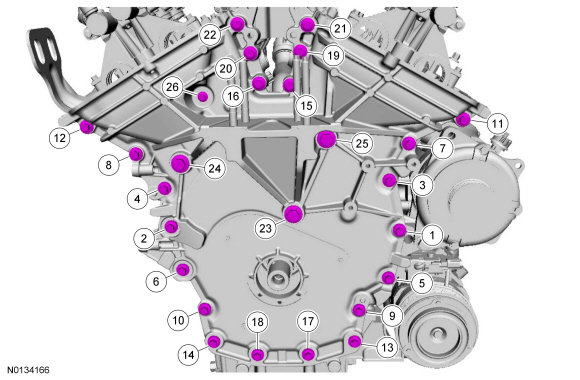
- Remove the 22 M8 engine front cover bolts.
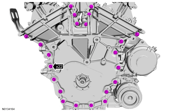
- Remove the M6 engine front cover bolt.
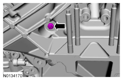
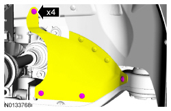
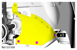
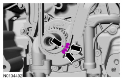
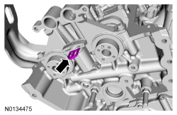
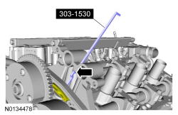
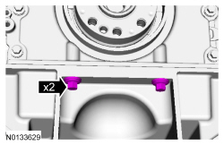
- Using a suitable pry tool, locate the 5 pry pads shown and pry the engine front cover loose and remove.
Installation
- NOTICE: Only use a 3M Roloc Bristle Disk (2-in white, part
number 07528) to clean the engine front cover. Do not use metal scrapers,
wire brushes or any other power abrasive disk to clean front cover.
Clean the engine front cover using a 3M Roloc Bristle Disk (2-in white, part number 07528) in a suitable tool turning at the recommended speed of 15,000 rpm.
- Thoroughly wash the engine front cover to remove any foreign material, including any abrasive particles created during the cleaning process.
- NOTICE: Place clean, lint-free shop towels over exposed engine
cavities. Carefully remove the towels so foreign material is not dropped
into the engine. Any foreign material (including any material created while
cleaning gasket surfaces) that enters the oil passages or the oil pan, may
cause engine failure.
NOTICE: Do not use wire brushes, power abrasive discs or 3M Roloc Bristle Disk (2-in white part number 07528) to clean the sealing surfaces of engine block, cylinder heads, and oil pan. These tools can cause contamination that will cause premature engine failure. Remove all traces of the gasket.
Clean the sealing surfaces of the cylinder heads, the cylinder block and the oil pan in the following sequence.- Remove any large deposits of silicone or gasket material.
- Apply silicone gasket remover and allow to set for several minutes.
- Remove the silicone gasket remover. A second application of silicone gasket remover may be required if residual traces of silicone or gasket material remain.
- Apply metal surface prep to remove any remaining traces of oil or coolant and to prepare the surfaces to bond. Do not attempt to make the metal shiny. Some staining of the metal surfaces is normal.
- Make sure the 2 locating dowel pins are seated correctly in the cylinder block.
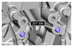
- Install the Alignment Pins.
- NOTICE: Failure to use Motorcraft High Performance Engine RTV
Silicone may cause the engine oil to foam excessively and result in serious
engine damage.
NOTE: The engine front cover and bolts 7, 8, 15, 17, 18, 21 and 22 must be installed within 4 minutes of the initial sealant application. The remainder of the engine front cover bolts must be installed and tightened within 35 minutes of the initial sealant application. If the time limits are exceeded, the sealant must be removed, the sealing area cleaned and sealant reapplied. To clean the sealing area, use silicone gasket remover and metal surface prep. Failure to follow this procedure can cause future oil leakage.
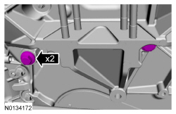
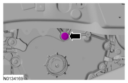
Apply a 3.0 mm (0.11 in) bead of Motorcraft High Performance Engine RTV Silicone to the engine front cover sealing surfaces including the 4 inner bolt bosses.- Apply a 5.5 mm (0.21 in) bead of Motorcraft High Performance Engine RTV Silicone to the oil pan-to-cylinder block joint and the cylinder head-to-cylinder block joint areas of the engine front cover in 5 places as indicated.
- NOTE: Make sure the 2 locating dowel pins are seated correctly in
the cylinder block.
Install the engine front cover and bolts 7, 8, 15, 17, 18, 21 and 22.
- Tighten in sequence to 3 Nm (27 lb-in).
- Remove the Alignment Pins.
- NOTE: Do not tighten the bolt at this time.
Install the M6 engine front cover bolt.

- NOTE: Do not tighten the bolts at this time.
Install the 2 upper M10 engine front cover bolts.
- NOTICE: Do not allow the A/C compressor to contact the
subframe. Failure to follow this direction may result in damage to the A/C
compressor.
NOTE: Do not tighten the bolt at this time.
Using the floor jack, lower the engine to allow installation of the lower M10 engine front cover bolt.- Install the lower M10 engine front cover bolt.
- NOTICE: Do not expose the Motorcraft High Performance Engine
RTV Silicone to engine oil for at least 90 minutes after installing the
engine front cover. Failure to follow this instruction may cause oil
leakage.
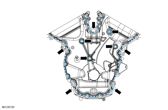
Install the remaining engine front cover bolts. Tighten all of the engine front cover bolts in the sequence shown in 7 stages:
- Stage 1: Tighten bolts 1 thru 22 to 10 Nm (89 lb-in).
- Stage 2: Tighten bolts 23, 24 and 25 to 15 Nm (133 lb-in).
- Stage 3: Tighten bolt 26 to 10 Nm (89 lb-in).
- Stage 4: Loosen bolt 26 one full turn.
- Stage 5: Tighten bolts 23, 24 and 25 to 30 Nm (22 lb-ft) plus an additional 90 degrees.
- Stage 6: Tighten bolts 1 thru 22 to 20 Nm (177 lb-in) plus an additional 45 degrees.
- Stage 7: Tighten bolt 26 to 10 Nm (89 lb-in) plus an additional 45 degrees.
- Use the floor jack to raise the engine to the installed position and
install the engine mount and the 3 bolts.
- Tighten to 90 Nm (66 lb-ft).

- Install the 4 engine mount nuts.
- Tighten to 63 Nm (46 lb-ft).

- NOTE: Apply clean engine oil to the crankshaft front seal bore in
the engine front cover.
Using the Front Crankshaft Seal Installer and Crankshaft Vibration Damper Installer, install a new crankshaft front seal.

- NOTE: Lubricate the outside diameter sealing surfaces and
crankshaft front seal inner lip with clean engine oil.
Using the Front Cover Oil Seal Installer and Crankshaft Vibration Damper Replacer, install the crankshaft pulley.
- Using the strap wrench, install the crankshaft pulley washer and new
bolt and tighten in 4 stages.
- Stage 1: Tighten to 120 Nm (89 lb-ft).
- Stage 2: Loosen one full turn.
- Stage 3: Tighten to 50 Nm (37 lb-ft).
- Stage 4: Tighten an additional 90 degrees.
- Install the RH inner fender splash shield. For additional information, refer to Section 501-02.
- Install the 3 accessory drive shield scrivets to the subframe.
- Install the RH front wheel and tire. For additional information, refer to Section 204-04.
- Position the generator and install the stud and nut.
- Tighten the stud to 8 Nm (71 lb-in).
- Tighten the nut to 47 Nm (35 lb-ft).
- Tighten the bolt to 47 Nm (35 lb-ft).
- Install the LH and RH valve covers. For additional information, refer to Valve Cover - LH and Valve Cover - RH in this section.
- Install the fuel tube-to-engine front cover bolt.
- Tighten the bolt to 10 Nm (89 lb-in).
- Connect the fuel supply tube to the fuel rail supply tube. For additional information, refer to Section 310-00.
- Using a new O-ring seal, connect the A/C pressure tube fitting and
install the nut.
- Tighten to 8 Nm (71 lb-in).

- Install the degas bottle. For additional information, refer to Section 303-03.
- Connect the coolant hose to the coolant inlet pipe.
- Remove the hose clamp pliers.

- Install the accessory drive belt and the tensioner. For additional information, refer to Section 303-05.
- NOTICE: Do not expose the Motorcraft High Performance Engine
RTV Silicone to engine oil for at least 90 minutes after installing the
engine front cover. Failure to follow this instruction may cause oil
leakage.
Fill the engine with clean engine oil.
- Connect the battery ground cable. For additional information, refer to Section 414-01.
- Fill the cooling system. For additional information, refer to Section 303-03.
- If equipped, install the skid plate and the 10 retainers.
- Tighten to 70 Nm (52 lb-ft).

- If equipped, install the underbody shield and attach the 4 retainers.

- Evacuate and recharge the A/C system. For additional information, refer to Section 412-00.
- After completing the repairs, use the scan tool to perform the Misfire Monitor Neutral Profile Correction procedure following the on-screen instructions.
Timing Drive Components
Special Tool(s)
Removal
NOTICE: During engine repair procedures, cleanliness is extremely important. Any foreign material, including any material created while cleaning gasket surfaces, that enters the oil passages, coolant passages or the oil pan may cause engine failure.
All engines
- Remove the engine front cover. For additional information, refer to Engine Front Cover in this section.
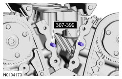
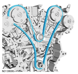
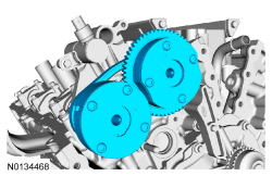
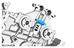
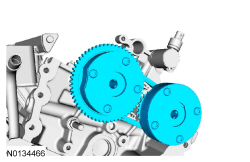
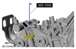
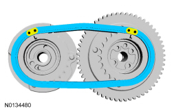
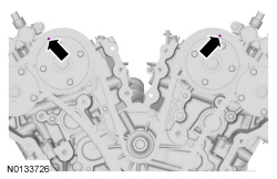
- Rotate the crankshaft clockwise and align the timing marks on the intake Variable Camshaft Timing (VCT) assemblies as shown.

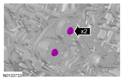
- Remove the 3 bolts and the LH valve train oil tube.

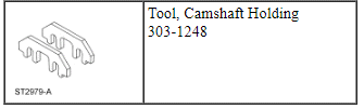
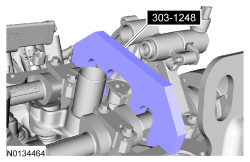
- NOTE: The Camshaft Holding Tool will hold the camshafts in the
Top Dead Center (TDC) position.
Install the Camshaft Holding Tool onto the flats of the LH camshafts.

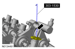
- Remove the 3 bolts and the RH valve train oil tube.
- NOTE: The Camshaft Holding Tool will hold the camshafts in
the TDC position.
Install the Camshaft Holding Tool onto the flats of the RH camshafts.

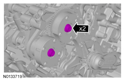
NOTE: The following 3 steps are for primary timing chains that the colored links are not visible.
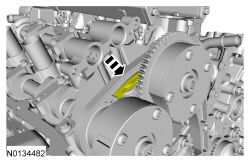
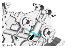
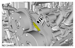
- Mark the timing chain link that aligns with the timing mark on the LH intake VCT assembly as shown.
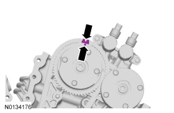
- Mark the timing chain link that aligns with the timing mark on the RH intake VCT assembly as shown.
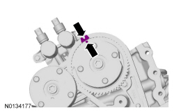
- NOTE: The crankshaft sprocket timing mark should be between the 2
colored links.
Mark the 2 timing chain links that align with the timing mark on the crankshaft sprocket as shown.
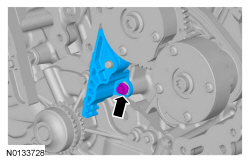
- Remove the 2 bolts and the primary timing chain tensioner.

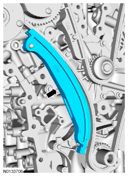
- Remove the primary timing chain tensioner arm.
- Remove the 2 bolts and the lower LH primary timing chain guide.

- NOTE: Removal of the VCT oil control solenoid will aid in the
removal of the primary timing chain.
NOTE: A slight twisting motion will aid in the removal of the VCT oil control solenoid.
NOTE: Keep the VCT oil control solenoid clean of dirt and debris.
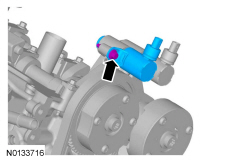
Remove the bolt and the LH intake VCT oil control solenoid.

- NOTE: Removal of the VCT oil control solenoid will aid in the
removal of the primary timing chain.
NOTE: A slight twisting motion will aid in the removal of the VCT oil control solenoid.
NOTE: Keep the VCT oil control solenoid clean of dirt and debris.
Remove the bolt and the RH intake VCT oil control solenoid.
- Remove the primary timing chain.
- Remove the crankshaft timing chain sprocket.

- NOTICE: Do not use power tools to remove the bolt or damage to
the LH primary timing chain guide may occur.
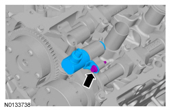
Remove the bolt and the upper LH primary timing chain guide.

- NOTE: The 2 VCT oil control solenoids are removed for clarity.
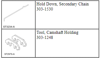
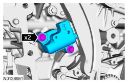
NOTE: The Secondary Chain Hold Down is inserted through a hole in the top of the mega cap.
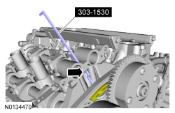
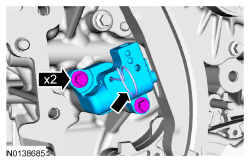
Compress the LH secondary timing chain tensioner and install the Secondary Chain Hold Down in the hole on the rear of the secondary timing chain tensioner guide and let it hold against the mega cap to retain the tensioner in the collapsed position.

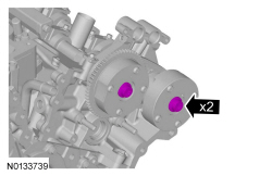
- Remove and discard the 2 LH VCT assembly bolts.

- Remove the 2 LH VCT assemblies and secondary timing chain.

- NOTE: The 2 VCT oil control solenoids are removed for clarity.
NOTE: The Secondary Chain Hold Down is inserted through a hole in the top of the mega cap.
Compress the RH secondary timing chain tensioner and install the Secondary Chain Hold Down in the hole on the rear of the secondary timing chain tensioner guide and let it hold against the mega cap to retain the tensioner in the collapsed position.
- Remove and discard the 2 RH VCT assembly bolts.

- Remove the 2 RH VCT assemblies and secondary timing chain.

- NOTICE: Do not use power tools to remove the bolt or damage to
the RH primary timing chain guide may occur.
Remove the bolt and the RH primary timing chain guide.

Engines with secondary timing chain tensioner removed
NOTICE: The following steps are only for the replacement of the secondary timing chain tensioners. Do not reuse the secondary timing chain tensioners if removed, or damage to the engine may occur.
- NOTE: A slight twisting motion will aid in the removal of
the VCT oil control solenoid.
NOTE: Keep the VCT oil control solenoid clean of dirt and debris.
Remove the LH exhaust VCT oil control solenoid.
- Remove the LH secondary timing chain tensioner shoe.
- Remove the LH secondary timing chain tensioner by pushing up from the bottom and remove.
- NOTE: A slight twisting motion will aid in the removal of
the VCT oil control solenoid.
NOTE: Keep the VCT oil control solenoid clean of dirt and debris.
Remove the RH exhaust VCT oil control solenoid.
- Remove the RH secondary timing chain tensioner shoe.
- Remove the RH secondary timing chain tensioner by pushing up from the bottom and remove.
Installation
All engines
- Install the RH primary timing chain guide and the bolt.
- Tighten to 10 Nm (89 lb-in).
Engines with secondary timing chain tensioner removed
NOTICE: The following steps are only for the replacement of the secondary timing chain tensioners. Do not reuse the secondary timing chain tensioners if removed or damage to the engine may occur.
- NOTE: Apply clean engine oil to the secondary timing chain
tensioner O-ring seals and mega cap bore.
NOTE: Do not remove the secondary timing chain tensioner shipping clip, until instructed to do so.
Install the RH secondary timing chain tensioner by pushing it down all the way until a snap is heard and the tensioner is seated all the way down the mega cap bore.
- Install the RH secondary timing chain tensioner shoe.
- Remove and discard the RH secondary timing chain tensioner shipping clip.
- Assemble the RH Variable Camshaft Timing (VCT) assembly, the RH exhaust
camshaft sprocket and the RH secondary timing chain.
- Align the colored links with the timing marks.

- NOTE: It may be necessary to rotate the camshafts slightly, to
install the RH secondary timing assembly.
Position the 2 RH VCT assemblies and secondary timing chain onto the camshafts by aligning the holes in the VCT assemblies with the dowel pins in the camshafts.
- Install the 2 new RH VCT bolts and tighten in 4 stages.
- Stage 1: Tighten to 40 Nm (30 lb-ft).
- Stage 2: Loosen one full turn.
- Stage 3: Tighten to 25 Nm (18 lb-ft).
- Stage 4: Tighten an additional 180 degrees.
- Activate the RH secondary timing chain tensioner by pressing down on the secondary tensioner top shoe until it bottoms out, let go of the tensioner and it will spring up putting tension on the chain.
- NOTICE: Do not use excessive force when installing the
Variable Camshaft Timing (VCT) oil control solenoid. Damage to the mega cap
could cause the cylinder head to be inoperable. If difficult to install
the VCT oil control solenoid, inspect the bore and VCT oil control solenoid
to ensure there are no burrs, sharp edges or contaminants present on the
mating surface. Only clean the external surfaces as necessary.
NOTE: A slight twisting motion will aid in the installation of the VCT oil control solenoid.
NOTE: Keep the VCT oil control solenoid clean of dirt and debris.
Install the RH exhaust VCT oil control solenoid.- Tighten to 8 Nm (71 lb-in) then an additional 20 degrees.
- NOTE: Apply clean engine oil to the secondary timing chain
tensioner O-ring seals and mega cap bore.
NOTE: Do not remove the secondary timing chain tensioner shipping clip, until instructed to do so.
Install the LH secondary timing chain tensioner by pushing it down all the way until a snap is heard and the tensioner is seated all the way down the mega cap bore.
- Install the LH secondary timing chain tensioner shoe.
- Remove and discard the LH secondary timing chain tensioner shipping clip.
- Assemble the 2 LH VCT assemblies and the LH secondary timing chain.
- Align the colored links with the timing marks.

- NOTE: It may be necessary to rotate the camshafts slightly, to
install the LH secondary timing assembly.
Position the 2 LH VCT assemblies and secondary timing chain onto the camshafts by aligning the holes in the VCT assemblies with the dowel pins in the camshafts.
- Install the 2 new LH VCT bolts and tighten in 4 stages.
- Stage 1: Tighten to 40 Nm (30 lb-ft).
- Stage 2: Loosen one full turn.
- Stage 3: Tighten to 25 Nm (18 lb-ft).
- Stage 4: Tighten an additional 180 degrees.
- Activate the LH secondary timing chain tensioner by pressing down on the secondary tensioner top shoe until it bottoms out, let go of the tensioner and it will spring up putting tension on the chain.
- NOTICE: Do not use excessive force when installing the
Variable Camshaft Timing (VCT) oil control solenoid. Damage to the mega cap
could cause the cylinder head to be inoperable. If difficult to install
the VCT oil control solenoid, inspect the bore and VCT oil control solenoid
to ensure there are no burrs, sharp edges or contaminants present on the
mating surface. Only clean the external surfaces as necessary.
NOTE: A slight twisting motion will aid in the installation of the VCT oil control solenoid.
NOTE: Keep the VCT oil control solenoid clean of dirt and debris.
Install the LH exhaust VCT oil control solenoid.- Tighten to 8 Nm (71 lb-in) then an additional 20 degrees.
Engines with secondary timing chain tensioner not removed
- Compress the RH secondary timing chain tensioner and install the Secondary Chain Hold Down to retain the tensioner in the collapsed position.
- Assemble the RH VCT assembly, the RH exhaust camshaft sprocket and the
RH secondary timing chain.
- Align the colored links with the timing marks.
- NOTE: It may be necessary to rotate the camshafts slightly, to
install the RH secondary timing assembly.
Position the 2 RH VCT assemblies and secondary timing chain onto the camshafts by aligning the holes in the VCT assemblies with the dowel pins in the camshafts.

- Install the 2 new RH VCT bolts and tighten in 4 stages.
- Stage 1: Tighten to 40 Nm (30 lb-ft).
- Stage 2: Loosen one full turn.
- Stage 3: Tighten to 25 Nm (18 lb-ft).
- Stage 4: Tighten an additional 180 degrees.
- NOTE: The 2 VCT oil control solenoids are removed for clarity.
Compress the RH secondary timing chain tensioner and remove the Secondary Chain Hold Down.
- Make sure the secondary timing chain is centered on the timing chain tensioner guides.

- Compress the LH secondary timing chain tensioner and install the Secondary Chain Hold Down to retain the tensioner in the collapsed position.
- Assemble the 2 LH VCT assemblies and the LH secondary timing chain.
- Align the colored links with the timing marks.
- NOTE: It may be necessary to rotate the camshafts slightly, to
install the LH secondary timing assembly.
Position the 2 LH VCT assemblies and secondary timing chain onto the camshafts by aligning the holes in the VCT assemblies with the dowel pins in the camshafts.

- Install the 2 new LH VCT bolts and tighten in 4 stages.
- Stage 1: Tighten to 40 Nm (30 lb-ft).
- Stage 2: Loosen one full turn.
- Stage 3: Tighten to 25 Nm (18 lb-ft).
- Stage 4: Tighten an additional 180 degrees.
- NOTE: The 2 VCT oil control solenoids are removed for clarity.
Compress the LH secondary timing chain tensioner and remove the Secondary Chain Hold Down.
- Make sure the secondary timing chain is centered on the timing chain tensioner guides.
All engines
- Install the upper LH primary timing chain guide and the bolt.
- Tighten to 10 Nm (89 lb-in).
- Install the crankshaft timing chain sprocket with timing dot mark out.

- NOTE: It may be necessary to rotate the camshafts slightly, to
align the timing marks.
Install the primary timing chain with the colored links aligned with the timing marks on the VCT assemblies and the crankshaft sprocket.

- Install the lower LH primary timing chain guide and the 2 bolts.
- Tighten to 10 Nm (89 lb-in).
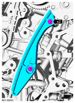
- Install the primary timing chain tensioner arm.

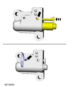
- Reset the primary timing chain tensioner.
- Release the ratchet detent.
- Using a soft-jawed vise, compress the ratchet plunger.
- Align the hole in the ratchet plunger with the hole in the tensioner housing.
- Install a suitable lockpin.

- NOTE: It may be necessary to rotate the camshafts slightly to
remove slack from the timing chain to install the tensioner.
Install the primary tensioner and the 2 bolts.
- Tighten to 10 Nm (89 lb-in).
- Remove the lockpin.
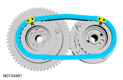
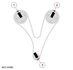
- As a post-check, verify correct alignment of all timing marks.
- There are 48 links in between the RH intake VCT assembly colored link (1) and the LH intake VCT assembly colored link (2).
- There are 35 links in between LH intake VCT assembly colored link (2) and the 2 crankshaft sprocket links (3).
- NOTICE: Do not use excessive force when installing the
Variable Camshaft Timing (VCT) oil control solenoid. Damage to the mega cap
could cause the cylinder head to be inoperable. If difficult to install
the VCT oil control solenoid, inspect the bore and VCT oil control solenoid
to ensure there are no burrs, sharp edges or contaminants present on the
mating surface. Only clean the external surfaces as necessary.
NOTE: A slight twisting motion will aid in the installation of the VCT oil control solenoid.
NOTE: Keep the VCT oil control solenoid clean of dirt and debris.
Install the LH intake VCT oil control solenoid and the bolt.- Tighten to 8 Nm (71 lb-in) then an additional 20 degrees.
- NOTICE: Do not use excessive force when installing the
Variable Camshaft Timing (VCT) oil control solenoid. Damage to the mega cap
could cause the cylinder head to be inoperable. If difficult to install
the VCT oil control solenoid, inspect the bore and VCT oil control solenoid
to ensure there are no burrs, sharp edges or contaminants present on the
mating surface. Only clean the external surfaces as necessary.
NOTE: A slight twisting motion will aid in the installation of the VCT oil control solenoid.
NOTE: Keep the VCT oil control solenoid clean of dirt and debris.
Install the RH intake VCT oil control solenoid and the bolt.- Tighten to 8 Nm (71 lb-in) then an additional 20 degrees.

- Remove the RH Camshaft Holding Tool.

- Install the RH valve train oil tube and the 3 bolts and tighten in 2
stages.
- Stage 1: Tighten to 8 Nm (71 lb-in).
- Stage 2: Tighten an additional 45 degrees.

- Remove the LH Camshaft Holding Tool.

- Install the LH valve train oil tube and the 3 bolts and tighten in 2
stages.
- Stage 1: Tighten to 8 Nm (71 lb-in).
- Stage 2: Tighten an additional 45 degrees.
- Install the engine front cover. For additional information, refer to Engine Front Cover in this section.
Oil Filter Adapter
Removal
All engines
- With the vehicle in NEUTRAL, position it on a hoist. For additional information, refer to Section 100-02.
- If equipped, release the 4 retainers and remove the underbody shield.
- If equipped, remove the 10 retainers and the skid plate.

Engines with oil cooler
- Remove the engine oil cooler. For additional information, refer to Oil Cooler in this section.
All engines
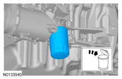
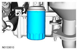
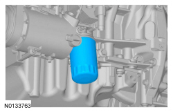
- Remove and discard the engine oil filter.
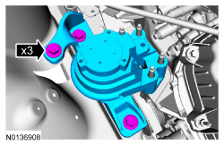
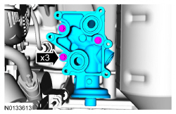
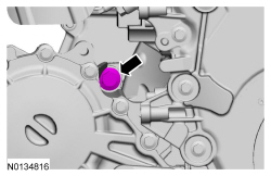
- NOTE: Oil filter adapter with oil cooler shown, oil filter
adapter without oil cooler similar.
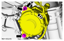
Remove the 3 bolts and the oil filter adapter.
- Discard the gasket.
- Clean and inspect all sealing surfaces.

Installation
All engines
- Using a new gasket, install the oil filter adapter and the 3 bolts.
- Tighten to 10 Nm (89 lb-in) plus an additional 45 degrees.
- NOTE: Do not lubricate the engine oil filter seal.
Install a new the engine oil filter.
- Tighten to 5 Nm (44 lb-in) and then rotate an additional 180 degrees.
Engines with oil cooler
- Install the engine oil cooler. For additional information, refer to Oil Cooler in this section.
All engines
- If equipped, install the skid plate and the 10 retainers.
- Tighten to 70 Nm (52 lb-ft).

- If equipped, install the underbody shield and attach the 4 retainers.

Oil Cooler
Removal
- With the vehicle in NEUTRAL, position it on a hoist. For additional information, refer to Section 100-02.
- If equipped, release the 4 retainers and remove the underbody shield.

- If equipped, remove the 10 retainers and the skid plate.

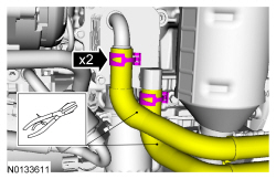
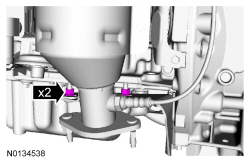
- Using hose clamp pliers, clamp the 2 oil cooler coolant hoses and remove the 2 coolant hoses from the oil cooler.
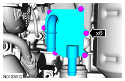
- NOTICE: If metal or aluminum material is present
in the oil cooler, mechanical concerns exist. Failure to correct these
concerns may cause engine failure. To diagnose mechanical concerns, refer
to Section 303-00.
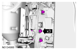
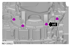
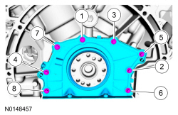
Remove the 6 bolts and the oil cooler.
- Discard the gaskets.
- Clean and inspect all sealing surfaces.
Installation
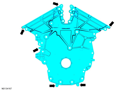
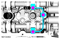
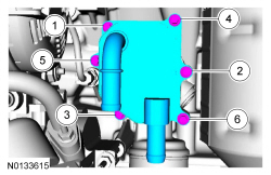
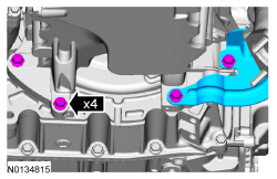
- Using a new gaskets, install the oil cooler and the 6 bolts.
- Tighten in the sequence shown to 10 Nm (89 lb-in).
- Install the 2 coolant hoses to the oil cooler.
- Remove the 2 hose clamp pliers.
- If equipped, install the skid plate and the 10 retainers.
- Tighten to 70 Nm (52 lb-ft).
- If equipped, install the underbody shield and attach the 4 retainers.

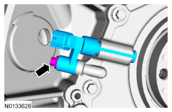
Engine Oil Pressure (EOP) Switch
Material
Removal and Installation
- With the vehicle in NEUTRAL, position it on a hoist. For additional information, refer to Section 100-02.
- If equipped, release the 4 retainers and remove the underbody shield.

- If equipped, remove the 10 retainers and the skid plate.
- To install, tighten to 70 Nm (52 lb-ft).

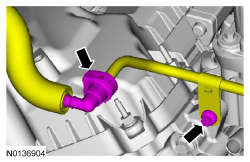
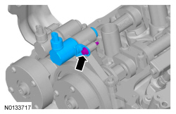
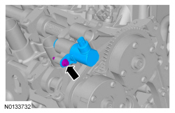
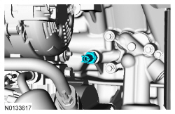
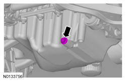
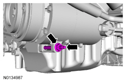
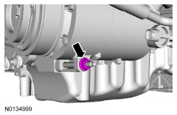
- Disconnect the Engine Oil Pressure (EOP) switch electrical connector.

- Remove the EOP switch.
- To install, tighten to 14 Nm (124 lb-in) plus an additional 180 degrees.
- To install, reverse the removal procedure.
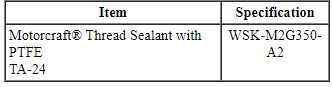
- Apply thread sealant with PTFE to the EOP switch threads prior to installation.
Engine Mount
Removal
- With the vehicle in NEUTRAL, position it on a hoist. For additional information, refer to Section 100-02.
- If equipped, release the 4 retainers and remove the underbody shield.

- If equipped, remove the 10 retainers and the skid plate.

- NOTICE: Failure to position the wood block and floor jack as
illustrated can result in damage to the oil pan.
Position a floor jack with a block of wood under the front of the oil pan.
- Detach the A/C line retainer from the shock tower bracket.

- Using hose clamp pliers, pinch the lower degas bottle hose and remove the hose from the coolant inlet pipe.
- Remove the degas bottle. For additional information, refer to Section 303-03.
- Remove the 4 engine mount nuts.
- Remove the 3 bolts and the engine mount.

Installation
- Install the engine mount and the 3 bolts.
- Tighten to 90 Nm (66 lb-ft).

- Install the 4 engine mount nuts.
- Tighten to 63 Nm (46 lb-ft).

- Install the degas bottle. For additional information, refer to Section 303-03.
- Connect the coolant hose to the coolant inlet pipe.
- Remove the hose clamp pliers.
- Attach the A/C line retainer to the shock tower bracket.
- If equipped, install the skid plate and the 10 retainers.
- Tighten to 70 Nm (52 lb-ft).

- If equipped, install the underbody shield and attach the 4 retainers.

Oil Pan
Material
Removal
NOTICE: During engine repair procedures, cleanliness is extremely important. Any foreign material, including any material created while cleaning gasket surfaces, that enters the oil passages, coolant passages or the oil pan, may cause engine failure.
All vehicles
- With the vehicle in NEUTRAL, position it on a hoist. For additional information, refer to Section 100-02.
- Remove the Air Cleaner (ACL) outlet pipe. For additional information, refer to Section 303-12.
- Remove the battery tray. For additional information, refer to Section 414-01.
- Remove the oil level indicator.
- Detach the wiring harness retainer from the starter stud bolt.
- Remove the starter stud bolt.

- Loosen the 3 upper bellhousing-to-engine bolts 5 mm (0.19 in).

- If equipped, release the 4 retainers and remove the underbody shield.

- If equipped, remove the 10 retainers and the skid plate.

- Remove the drain plug and drain the engine oil.
- Install the drain plug and tighten to 27 Nm (20 lb-ft).
- Remove and discard the engine oil filter.

- Remove the exhaust Y-pipe. For additional information, refer to Section 309-00.
- Remove the transaxle support insulator - anti-roll. For additional information, refer to Section 307-01A.
All-Wheel Drive (AWD) vehicles
- Remove the catalytic converter - RH manifold. For additional information, refer to Section 309-00.
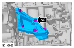
- Remove the 5 Power Transfer Unit (PTU) support bracket bolts and the PTU support bracket.

All vehicles
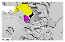
- Remove the A/C compressor nut.
- Remove the stud from the oil pan boss (stud will remain in compressor housing).
- Loosen the 3 LH bellhousing-to-engine bolts 5 mm (0.19 in).
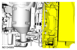
- NOTE: All-Wheel Drive (AWD) vehicle shown, Front Wheel Drive
(FWD) similar. Parts removed from graphic for clarity.
Loosen the RH engine-to-bellhousing bolt 5 mm (0.19 in).
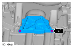
- Remove the 2 fasteners and the inspection cover.
- Remove the 2 LH catalytic converter bracket nuts.
- Remove the 4 oil pan-to-bellhousing bolts and the LH catalytic converter bracket.
- Separate the engine and transaxle 5 mm (0.19 in).
- Remove the 4 lower engine front cover bolts.

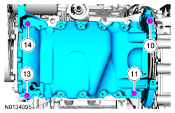
- Remove the 16 oil pan bolts.
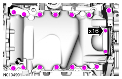
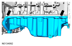
- Using a suitable pry tool, locate the pry pads and pry the oil pan loose and remove.
- NOTICE: Only use a 3M Roloc Bristle Disk (2-in white, part
number 07528) to clean the oil pan. Do not use metal scrapers, wire brushes
or any other power abrasive disk to clean. These tools cause scratches and
gouges that make leak paths.
Clean the engine oil pan using a 3M Roloc Bristle Disk (2-in white, part number 07528) in a suitable tool turning at the recommended speed of 15,000 rpm.
- Thoroughly wash the oil pan to remove any foreign material, including any abrasive particles created during the cleaning process.
- NOTICE: Do not use wire brushes, power abrasive discs or 3M
Roloc Bristle Disk (2-in white, part number 07528) to clean the sealing
surfaces. These tools cause scratches and gouges that make leak paths. They
also cause contamination that causes premature engine failure. Remove all
traces of the gasket.
Clean the sealing surfaces of the cylinder block and engine front cover in the following sequence.
- Remove any large deposits of silicone or gasket material.
- Apply silicone gasket remover and allow to set for several minutes.
- Remove the silicone gasket remover. A second application of silicone gasket remover may be required if residual traces of silicone or gasket material remain.
- Apply metal surface prep to remove any remaining traces of oil and to prepare the surfaces to bond. Do not attempt to make the metal shiny. Some staining of the metal surfaces is normal.
Installation
All vehicles
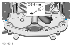
- Apply a 5.5 mm (0.21 in) bead of Motorcraft High Performance Engine RTV Silicone to the 2 engine front cover-to-cylinder block joint areas on the sealing surface of the oil pan.
- NOTICE: Failure to use Motorcraft High Performance Engine RTV
Silicone may cause the engine oil to foam excessively and result in serious
engine damage.
NOTE: The oil pan and the 4 specified bolts must be installed and the oil pan aligned to the cylinder block within 4 minutes of sealant application. Final tightening of the oil pan bolts must be carried out within 60 minutes of sealant application.
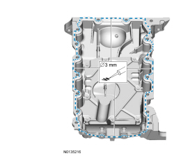
Apply a 3 mm (0.11 in) bead of Motorcraft High Performance Engine RTV Silicone to the sealing surface of the oil pan-to-engine block and to the oil pan-to-engine front cover mating surface.
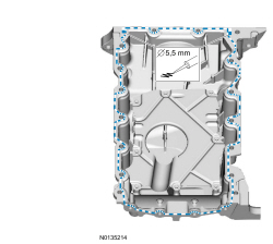
- Apply a 5.5 mm (0.21 in) bead of Motorcraft High Performance Engine RTV Silicone to the 2 crankshaft seal retainer plate-to-cylinder block joint areas on the sealing surface of the oil pan.
- NOTE: The oil pan and the 4 specified bolts must be installed
within 4 minutes of the start of sealant application.
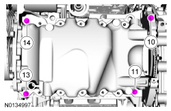
NOTE: Keep the oil pan as close as possible to the transmission while installing, then slide forward towards the engine front cover to prevent wiping off of the sealant.
Install the oil pan and bolts 10, 11, 13 and 14 finger tight.
- Draw the bellhousing up to the engine by tightening the LH
bellhousing-to-engine bolt.
- Do not torque at this time.
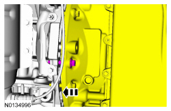
- NOTE: All-Wheel Drive (AWD) vehicle shown, Front Wheel Drive
(FWD) similar. Parts removed from graphic for clarity.
Draw the bellhousing up to the engine by tightening the RH engine-to-bellhousing bolt.
- Do not torque at this time.
- Install the LH catalytic converter bracket and the 4 oil
pan-to-bellhousing bolts.
- Do not torque at this time.

- Install the 2 LH catalytic converter bracket nuts.
- Tighten to 30 Nm (22 lb-ft).

- Install the A/C compressor stud and nut.
- Tighten the stud to 9 Nm (80 lb-in).
- Hand tighten the nut.

- Tighten bolts 10, 11, 13 and 14 in the sequence shown to 3 Nm (27 lb-in).
- Install the 4 lower engine front cover bolts.
- Do not torque at this time.
- Install the remaining oil pan bolts and tighten in the sequence shown.
- Tighten bolts 1 through 9 and 11 through 14 to 20 Nm (177 lb-in), then rotate an additional 45 degrees.
- Tighten bolts 15 and 16 to 10 Nm (89 lb-in), then rotate an additional 45 degrees.
- Tighten bolt 10 to 20 Nm (177 lb-in), then rotate an additional 90 degrees.
- Tighten the 4 lower engine front cover bolts to 24 Nm (18 lb-ft).

- Tighten the A/C compressor nut to 25 Nm (18 lb-ft).
- Tighten the 4 oil pan-to-bellhousing bolts to 48 Nm (35 lb-ft).
- NOTE: All-Wheel Drive (AWD) vehicle shown, Front Wheel Drive
(FWD) similar. Parts removed from graphic for clarity.
Tighten the RH engine-to-bellhousing bolt to 48 Nm (35 lb-ft).

- Tighten the 3 LH bellhousing-to-engine bolts to 48 Nm (35 lb-ft).
- Install the inspection cover and the 2 fasteners.

All-Wheel Drive (AWD) vehicles
- Install the Power Transfer Unit (PTU) support bracket and the 5 bolts.
- Tighten to 70 Nm (52 lb-ft).
- Install the catalytic converter - RH manifold. For additional information, refer to Section 309-00.
All vehicles
- Tighten the 3 upper bellhousing-to-engine bolts to 48 Nm (35 lb-ft).
- NOTE: Do not lubricate the engine oil filter gasket.
Install a new engine oil filter.
- Tighten to 5 Nm (44 lb-in) and then rotate an additional 180 degrees.
- Install the transaxle support insulator - anti-roll. For additional information, refer to Section 307-01A.
- Install the exhaust Y-pipe. For additional information, refer to Section 309-00.
- If equipped, install the skid plate and the 10 retainers.
- Tighten to 70 Nm (52 lb-ft).

- If equipped, install the underbody shield and attach the 4 retainers.

- Install the starter stud bolt.
- Tighten to 27 Nm (20 lb-in).
- Attach the wiring harness retainer to the starter stud bolt.
- Install the oil level indicator.

- Install the battery tray. For additional information, refer to Section 414-01.
- Install the Air Cleaner (ACL) outlet pipe. For additional information, refer to Section 303-12.
- NOTICE: Do not expose the Motorcraft High Performance Engine
RTV Silicone to engine oil for at least 90 minutes after installing the oil
pan. Failure to follow these instructions may cause engine oil leakage.
Fill the engine with clean engine oil.
Oil Pump Screen and Pickup Tube
Removal
NOTICE: During engine repair procedures, cleanliness is extremely important. Any foreign material, including any material created while cleaning gasket surfaces, that enters the oil passages, coolant passages or the oil pan may cause engine failure.
- Remove the oil pan. For additional information, refer to Oil Pan in this section.
- Remove the 2 bolts and the oil pump screen and pickup tube.
- Discard the O-ring seal.

Installation
- Using a new O-ring seal, install the oil pump screen and pickup tube and
the 2 bolts.
- Tighten to 10 Nm (89 lb-in).
- Install the oil pan. For additional information, refer to Oil Pan in this section.
Crankshaft Rear Seal with Retainer Plate
Material
Removal
NOTICE: During engine repair procedures, cleanliness is extremely important. Any foreign material, including any material created while cleaning gasket surfaces that enters the oil passages, coolant passages or the oil pan, may cause engine failure.
- With the vehicle in NEUTRAL, position it on a hoist. For additional information, refer to Section 100-02.
- Remove the flexplate. For additional information, refer to Flexplate in this section.
- Remove the crankshaft sensor ring.

- Disconnect the Crankshaft Position (CKP) sensor electrical connector.
- Remove the bolt and the CKP sensor.

- Remove the 2 oil pan-to-crankshaft rear seal retainer bolts.

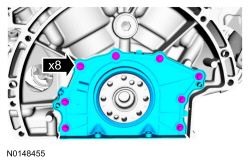
- Remove the 8 bolts and the crankshaft rear seal retainer plate.
- Discard the plate and seal assembly.
- NOTICE: Place clean, lint-free shop towels over exposed engine
cavities. Carefully remove the towels so foreign material is not dropped
into the engine. Any foreign material (including any material created while
cleaning gasket surfaces) that enters the oil passages or the oil pan, may
cause engine failure.
NOTICE: Do not use wire brushes, power abrasive discs or 3M Roloc Bristle Disk (2-in white, part number 07528) to clean the sealing surfaces. These tools cause scratches and gouges that make leak paths. They also cause contamination that will cause premature engine failure. Remove all traces of the gasket.
Clean the sealing surfaces of the cylinder block and oil pan flange in the following sequence.- Remove any large deposits of silicone or gasket material.
- Apply silicone gasket remover and allow to set for several minutes.
- Remove the silicone gasket remover. A second application of silicone gasket remover may be required if residual traces of silicone or gasket material remain.
- Apply metal surface prep to remove any remaining traces of oil or coolant and to prepare the surfaces to bond. Do not attempt to make the metal shiny. Some staining of the metal surfaces is normal.
Installation
- NOTICE: Failure to use Motorcraft High Performance Engine RTV
Silicone may cause the engine oil to foam excessively and result in serious
engine damage.
NOTE: The crankshaft rear seal retainer must be installed and the bolts tightened within 10 minutes of sealant application.
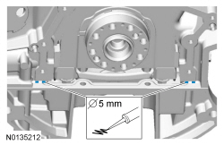
Apply 5 mm (0.196 in) beads of Motorcraft High Performance Engine RTV Silicone to the 2 cylinder block/oil pan joints.
- NOTICE: Failure to use Motorcraft High Performance Engine RTV
Silicone may cause the engine oil to foam excessively and result in serious
engine damage.
NOTE: The crankshaft rear seal retainer must be installed and the bolts tightened within 10 minutes of sealant application.
NOTE: The stamped steel crankshaft rear seal retainer plate comes with the crankshaft rear seal.
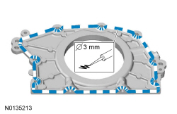
Apply a 3 mm (0.11 in) bead of Motorcraft High Performance Engine RTV Silicone to the sealing surface of the crankshaft rear seal retainer.
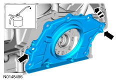
- NOTE: Use the 2 handles during installation to avoid touching the
sealant.
NOTE: Lubricate the crankshaft rear seal with clean engine oil.
Install the crankshaft rear seal retainer at an angle above the oil pan flange to avoid scraping off the sealer. Tilt the seal retainer up and onto the rear of the cylinder block.
- Install the 8 bolts and tighten in the sequence shown to 10 Nm (89 lb-in).
- Install the 2 oil pan to crankshaft rear seal retainer bolts.
- Tighten to 10 Nm (89 lb-in) plus an additional 45 degrees.
- Install the Crankshaft Position (CKP) sensor and install the bolt.
- Tighten to 10 Nm (89 lb-in).
- Connect the CKP sensor electrical connector.

- Install the crankshaft sensor ring.
- Install the flexplate. For additional information, refer to Flexplate in this section.
Oil Pump
Special Tool(s)
Removal
NOTICE: During engine repair procedures, cleanliness is extremely important. Any foreign material, including any material created while cleaning gasket surfaces, that enters the oil passages, coolant passages or the oil pan may cause engine failure.
- Remove the engine front cover. For additional information, refer to Engine Front Cover in this section.
- Rotate the crankshaft clockwise and align the timing marks on the intake Variable Camshaft Timing (VCT) assemblies as shown.
- Remove the 3 bolts and the LH valve train oil tube.

- NOTE: The Camshaft Holding Tool will hold the camshafts in the
Top Dead Center (TDC) position.
Install the Camshaft Holding Tool onto the flats of the LH camshafts.

- Remove the 3 bolts and the RH valve train oil tube.

- NOTE: The Camshaft Holding Tool will hold the camshafts in
the TDC position.
Install the Camshaft Holding Tool onto the flats of the RH camshafts.
NOTE: The following 3 steps are for primary timing chains that the colored links are not visible.
- Mark the timing chain link that aligns with the timing mark on the LH intake VCT assembly as shown.

- Mark the timing chain link that aligns with the timing mark on the RH intake VCT assembly as shown.

- NOTE: The crankshaft sprocket timing mark should be between the 2
colored links.
Mark the 2 timing chain links that align with the timing mark on the crankshaft sprocket as shown.

- Remove the 2 bolts and the primary timing chain tensioner.
- Remove the primary timing chain tensioner arm.

- Remove the 2 bolts and the lower LH primary timing chain guide.
- Position the timing chain aside.

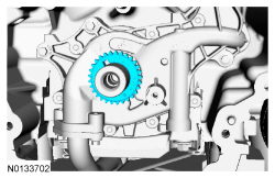
- Position the primary timing chain aside and remove the crankshaft timing chain sprocket.

- Remove the 2 bolts and the oil pump screen and pickup tube.
- Discard the O-ring seal.
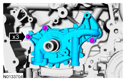
- Remove the 3 bolts and the oil pump.
Installation
- Install the oil pump and the 3 bolts.
- Tighten to 10 Nm (89 lb-in).

- Using a new O-ring seal, install the oil pump screen and pickup tube and
the 2 bolts.
- Tighten to 10 Nm (89 lb-in).

- Install the crankshaft timing chain sprocket with timing dot mark out.
- NOTE: It may be necessary to rotate the camshafts slightly, to
align the timing marks.
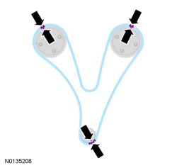
Position the primary timing chain with the colored links aligned with the timing marks on the VCT assemblies and the crankshaft sprocket.
- Install the lower LH primary timing chain guide and the 2 bolts.
- Tighten to 10 Nm (89 lb-in).

- Install the primary timing chain tensioner arm.

- Reset the primary timing chain tensioner.
- Release the ratchet detent.
- Using a soft-jawed vise, compress the ratchet plunger.
- Align the hole in the ratchet plunger with the hole in the tensioner housing.
- Install a suitable lockpin.
- NOTE: It may be necessary to rotate the camshafts slightly to
remove slack from the timing chain to install the tensioner.
Install the primary tensioner and the 2 bolts.
- Tighten to 10 Nm (89 lb-in).
- Remove the lockpin.

- As a post-check, verify correct alignment of all timing marks.
- There are 48 links in between the RH intake VCT assembly colored link (1) and the LH intake VCT assembly colored link (2).
- There are 35 links in between LH intake VCT assembly colored link (2) and the 2 crankshaft sprocket links (3).

- Remove the RH Camshaft Holding Tool.

- Install the RH valve train oil tube and the 3 bolts and tighten in 2
stages.
- Stage 1: Tighten to 8 Nm (71 lb-in).
- Stage 2: Tighten an additional 45 degrees.

- Remove the LH Camshaft Holding Tool.
- Install the LH valve train oil tube and the 3 bolts and tighten in 2
stages.
- Stage 1: Tighten to 8 Nm (71 lb-in).
- Stage 2: Tighten an additional 45 degrees.

- Install the engine front cover. For additional information, refer to Engine Front Cover in this section.
 Specifications, Description and Operation, General Procedures
SPECIFICATIONS
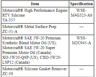
Material
General Specifications
Torque Specifications
a Tighten to 10 Nm (89 lb-in) plus an additional 720 degrees.
b Tighten to 16 Nm (142 lb-in) plus an additional ...
 Removal
Engine
Special Tool(s)
WARNING: Do not smoke, carry lighted tobacco or have an open flame of any
type when working on or near any fuel-related component. Highly flammable
mixtures are always ...
Other materials:
Vehicle storage
If you plan on storing your vehicle for an extended period of time
(30 days or more), read the following maintenance recommendations to
make sure your vehicle stays in good operating condition.
All motor vehicles and their components were engineered and tested for
reliable, regular driving. Lo ...
Windshield wipers
Note: Fully defrost the windshield before switching on the windshield
wipers.
Note: Make sure you switch off the windshield wipers before entering a
car wash.
Note: Clean the windshield and wiper blades if they begin to leave
streaks
or smears. If that does not resolve the issue, install ...
Removal and Installation
Exterior Mirror
Removal and Installation
NOTE: Do not remove the exterior mirror assembly when repairing an
individual part. Individual components can be installed without removing the
exterior mirror.
Remove the sail panel.
Pull outward on the sail panel to release the retaining clips.
...
