SPECIFICATIONS
Material
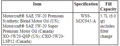
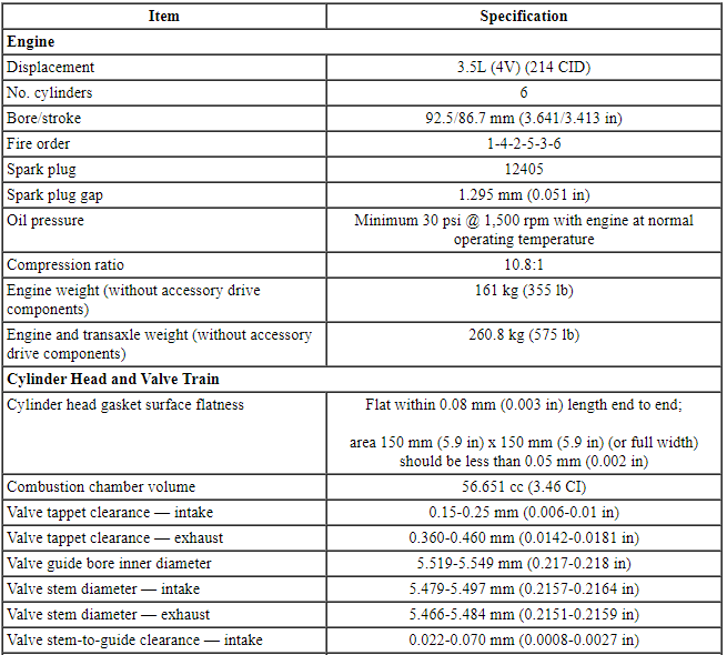
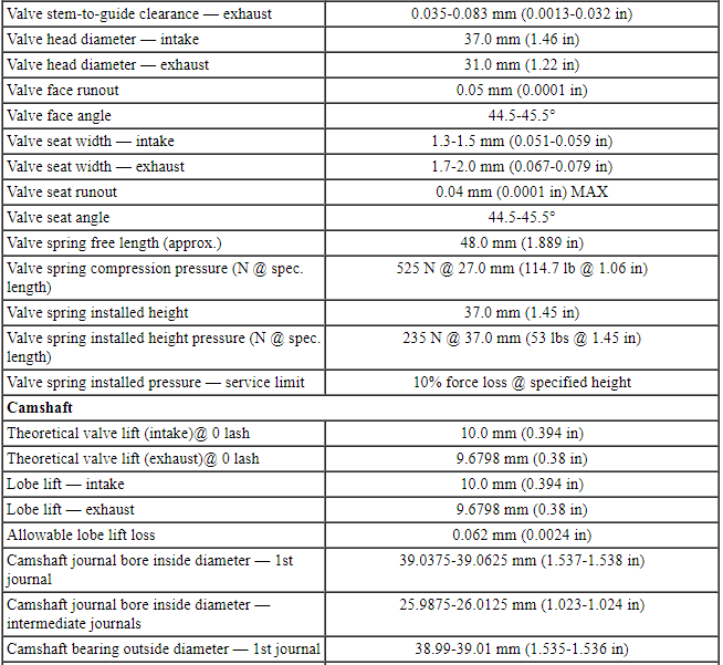
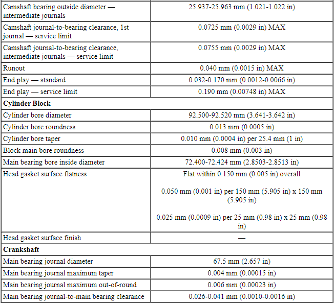
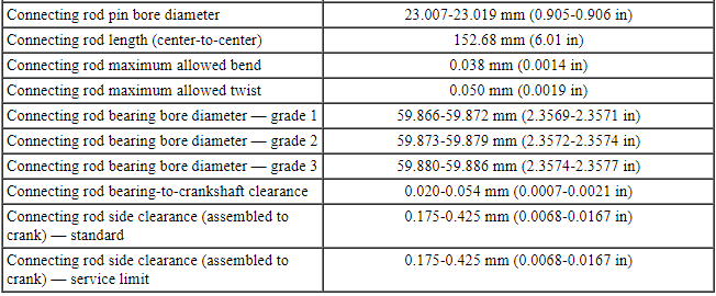
General Specifications
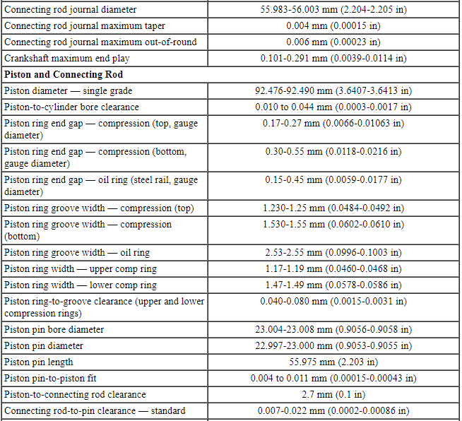
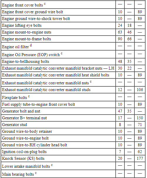
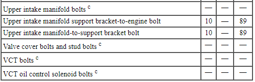
Torque Specifications
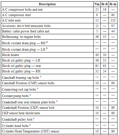
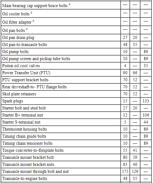
a Tighten to 10 Nm (89 lb-in) plus an additional 720 degrees.
b Tighten to 16 Nm (142 lb-in) plus an additional 180 degrees.
c Refer to the procedure in this section.
d Tighten to 5 Nm (44 lb-in) plus an additional 180 degrees.
DESCRIPTION AND OPERATION
Engine
Overview
The 3.5L (4V) is a V-6 engine with the following features:
- Dual overhead camshafts
- Four valves per cylinder
- Sequential Multi-Port Fuel Injection (SFI)
- Composite upper and lower intake manifolds
- Aluminum cylinder heads
- An aluminum, 60-degree V-cylinder block
- Timing chain driven coolant pump
- Twin independent Variable Camshaft Timing (VCT) system
- An electronic ignition system with 6 ignition coils
Engine Identification
For quick identification, refer to the safety certification decal.
The decal is located on the LH front door lock face panel.
Engine Code Information Label
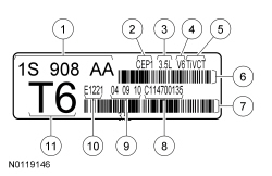
- Engine part number
- Engine plant (Cleveland)
- Engine displacement
- Engine configuration
- Twin independent VCT
- Bar code
- Bar code
- Running number
- Engine build date (DDMMYY)
- Plant shift line
- Derivative code
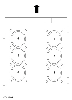
Engine Cylinder Identification
System Operation
Engine Oil Flow Illustration
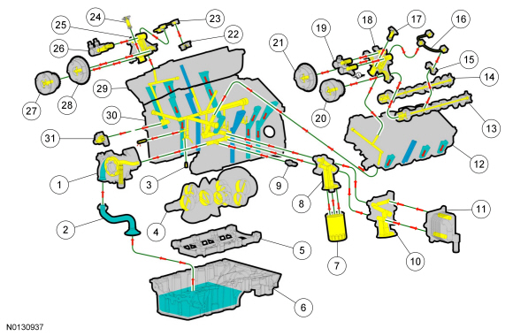
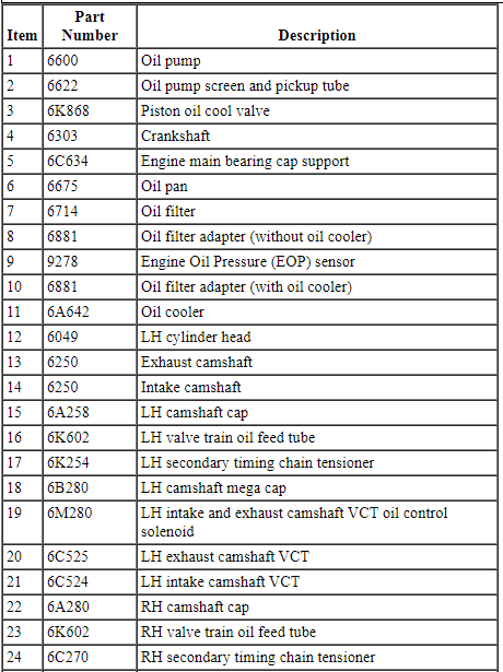
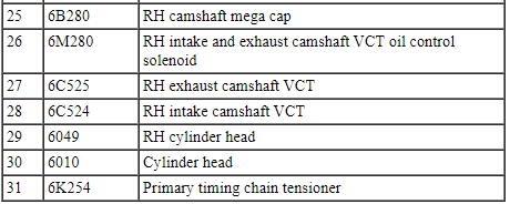
Lubrication System
The engine lubrication system is of the force-feed type in which oil is supplied under full pressure to the crankshaft, connecting rod bearings, timing chain tensioners, piston oil cooling jets and VCT solenoids. The flow of oil to the valve tappets and valve train is controlled by a restricting orifice located in the cylinder head, front camshaft cap.
Oil Pump
The lubrication system is designed to provide optimum oil flow to critical components of the engine through its entire operating range.
The heart of the system is a positive displacement internal gear oil pump.
Generically, this design is known as a gerotor pump, which operates as follows:
- The oil pump is mounted on the front face of the cylinder block.
- The inner rotor is piloted on the crankshaft post and is driven through flats on the crankshaft.
- System pressure is limited by an integral, internally-vented relief valve which directs the bypassed oil back to the inlet side of the oil pump.
- Oil pump displacement has been selected to provide adequate volume to make sure of correct oil pressure both at hot idle and maximum speed.
- The relief valve calibration protects the system from excessive pressure during high-viscosity conditions.
- The relief valve is designed to provide adequate connecting rod bearing lubrication under high temperature and high-speed conditions.
Valve Train
The valve train uses Direct Acting Mechanical Buckets (DAMB). The camshaft lobes are positioned directly above mechanical buckets which are positioned on top of the valves.
Twin Independent VCT System
The twin independent VCT system allows variable control of intake valve closing which optimizes combustion at full load providing improved power and low speed torque (broadening the torque curve) which enables variable valve overlap which provides better fuel economy and emissions and provides optimized cold start operation with improved exhaust emissions.
DIAGNOSIS AND TESTING
Engine
For basic engine mechanical concerns, refer to Section 303-00. For driveability concerns, refer to the Powertrain Control/Emissions Diagnosis (PC/ED) manual.
GENERAL PROCEDURES
Valve Clearance Check
- Remove the valve covers. For additional information, refer to Valve Cover - LH and Valve Cover - RH in this section.
- NOTE: Engine must be at room temperature before measuring. The
valve clearance must be measured with the camshaft at base circle. The
engine will have to be rotated with the crankshaft pulley bolt to bring each
valve to base circle.
Use a feeler gauge to measure the clearance of each valve and record its location. A midrange clearance is the most desirable:
- Intake: 0.15-0.25 mm (0.006-0.01 in)
- Exhaust: 0.360-0.460 mm (0.0142-0.0181 in)
- NOTE: The number on the valve tappet reflects the thickness of
the valve tappet. For example, a tappet with the number 3.310 has the
thickness of 3.31 mm (0.13 in).
If any of the valve clearances are out of specification, select new tappets using this formula: tappet thickness = measured clearance + the base tappet thickness - most desirable thickness.
Select the tappets and mark the installation location.
- If required, install the new selected valve tappets in the marked locations. For additional information, refer to Valve Tappets in this section.

 In-Vehicle Repair
Upper Intake Manifold
Removal
NOTICE: If the engine is repaired or replaced because of upper
engine failure, typically including valve or piston damage, check the intake
manifold for metal debr ...
Other materials:
Diagnosis and Testing
Rear View Mirrors - Exterior
DTC Chart(s)
Diagnostics in this manual assume a certain skill level and knowledge of
Ford-specific diagnostic practices. REFER to Section 100-00 for information
regarding these diagnostic practices.
DDM DTC Chart
DSM DTC Chart
Symptom Chart(s)
Di ...
In-Vehicle Repair
Upper Intake Manifold
Removal
NOTICE: If the engine is repaired or replaced because of upper
engine failure, typically including valve or piston damage, check the intake
manifold for metal debris. If metal debris is found, install a new intake
manifold. Failure to follow these instructions c ...
Active Park Assist
SPECIFICATIONS
General Specifications
DESCRIPTION AND OPERATION
Active Park Assist
Component Location
Active park assist sensor
Active park assist switch
Parking aid module
Overview
The active park assist system is a supplementary parking aid that assists the
operator in detecting an availab ...
