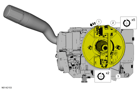
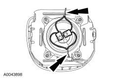
Clockspring Adjustment
WARNING: If the clockspring is not correctly centralized, it may fail prematurely. If in doubt, repeat the centralizing procedure. Failure to follow these instructions may increase the risk of serious personal injury or death in a crash.
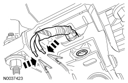
NOTE: Typical SCCM and clockspring shown, others similar.
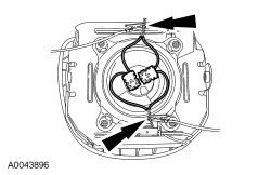
- NOTICE: Do not over-rotate the clockspring inner rotor. The
internal ribbon wire is connected to the clockspring rotor. The internal
ribbon wire acts as a stop and can be broken from its internal connection.
Failure to follow this instruction may result in component damage and/or
system failure.
NOTE: After final positioning, do not allow the clockspring rotor to rotate from this position.
- Turn until resistance is felt, then turn clockwise so the electrical connector is in the 12 o'clock position.
- -
- -
Supplemental Restraint System (SRS) Depowering and Repowering
Depowering
WARNING: Wear eye and ear protection when servicing a vehicle. Failure to follow this instruction may result in serious personal injury.
WARNING: Never probe the electrical connectors on airbag, Safety Canopy or side air curtain assemblies. Failure to follow this instruction may result in the accidental deployment of these assemblies, which increases the risk of serious personal injury or death.
WARNING: Do not handle, move or change the original horizontal mounting position of the restraints control module (RCM) while the RCM is connected and the ignition switch is ON. Failure to follow this instruction may result in the accidental deployment of the Safety Canopy and cause serious personal injury or death.
WARNING: To reduce the risk of accidental deployment, do not use any memory saver devices. Failure to follow this instruction may result in serious personal injury or death.
NOTE: The air bag warning indicator illuminates when the correct RCM fuse is removed and the ignition is ON.
NOTE: The SRS must be fully operational and free of faults before releasing the vehicle to the customer.
- Turn all vehicle accessories OFF.
- Turn the ignition OFF.
- At the BCM, located below the LH side of the instrument panel, remove the cover and the RCM fuse 41 (7.5A) from the BCM. For additional information, refer to the Wiring Diagrams manual.
- Turn the ignition ON and monitor the air bag warning indicator for at least 30 seconds. The air bag warning indicator remains lit continuously (no flashing) if the correct RCM fuse is removed. If the air bag warning indicator is not lit continuously, remove the correct RCM fuse before proceeding.
- Turn the ignition OFF.
- WARNING:
Always deplete the backup power supply before repairing or installing any
new front or side air bag supplemental restraint system (SRS) component and
before servicing, removing, installing, adjusting or striking components
near the front or side impact sensors or the restraints control module
(RCM). Nearby components include doors, instrument panel, console, door
latches, strikers, seats and hood latches. Refer to the Description and
Operation portion of Section 501-20B for location of the RCM and impact
sensor(s). To deplete the backup power supply energy, disconnect the battery
ground cable and wait at least 1 minute. Be sure to disconnect auxiliary
batteries and power supplies (if equipped). Failure to follow these
instructions may result in serious personal injury or death in the event of
an accidental deployment.
Disconnect the battery ground cable and wait at least one minute. Refer to Section 414-01.
Repowering Procedure
Vehicles With Ignition Switch
- Turn the ignition from OFF to ON.
- Install RCM fuse 41 (7.5A) to the BCM and close the cover.
- WARNING:
Make sure no one is in the vehicle and there is nothing blocking or placed
in front of any airbag when the battery is connected. Failure to follow
these instructions may result in serious personal injury in the event of an
accidental deployment.
Connect the battery ground cable.
- Prove out the SRS as follows:
With the ignition OFF, wait 10 seconds, then turn the ignition ON and monitor the air bag warning indicator with the air bag modules installed. The air bag warning indicator illuminates continuously for approximately 6 seconds and then turns off. If a SRS fault is present, the air bag warning indicator will:
- fail to light.
- remain lit continuously.
- flash.
The flashing might not occur until approximately 30 seconds after the ignition has been turned from OFF to ON. This is the time required to complete testing of the SRS. If the air bag warning indicator is inoperative and a SRS fault exists, a chime sounds in a pattern of 5 sets of 5 beeps. If this occurs, diagnose and repair the air bag warning indicator and any SRS faults.
Vehicles With Push-Button Start System
- Install RCM fuse 41 (7.5A) to the BCM and install the cover.
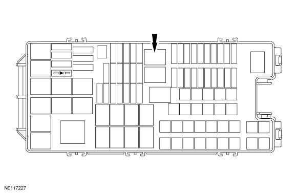
- Remove BJB relay 88 (run/start relay).
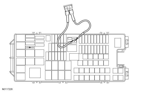
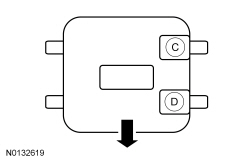
- Install a 30A fused jumper wire in BJB relay 88 (run/start relay) cavities 3 and 5, as shown.
- WARNING:
Make sure no one is in the vehicle and there is nothing blocking or placed
in front of any airbag when the battery is connected. Failure to follow
these instructions may result in serious personal injury in the event of an
accidental deployment.
Connect the battery ground cable.
- Wait at least 30 seconds, then remove the fused jumper wire from the BJB.
- Install BJB relay 88 (run/start relay) and cover.
- Prove out the SRS as follows:
With the ignition OFF, wait 10 seconds, then turn the ignition ON and monitor the air bag warning indicator with the air bag modules installed. The air bag warning indicator illuminates continuously for approximately 6 seconds and then turns off. If a SRS fault is present, the air bag warning indicator will:
- fail to light.
- remain lit continuously.
- flash.
The flashing might not occur until approximately 30 seconds after the ignition has been turned from OFF to ON. This is the time required to complete testing of the SRS. If the air bag warning indicator is inoperative and a SRS fault exists, a chime sounds in a pattern of 5 sets of 5 beeps. If this occurs, diagnose and repair the air bag warning indicator and any SRS faults.
- Clear all CMDTCs from the RCM and OCSM.
Inspection and Repair After a Supplemental Restraint System (SRS) Deployment
WARNING: Remove restraint system diagnostic tools from the vehicle prior to road testing. If tools are not removed, the supplemental restraint system (SRS) device may not deploy in a crash. Failure to follow this instruction may result in serious personal injury or death in a crash and possibly violate vehicle safety standards.
NOTE: After diagnosing or repairing a SRS, the restraint system diagnostic tools (if required) must be removed before operating the vehicle over the road.
NOTE: Deployable devices (such as air bag modules, pretensioners) may deploy alone or in various combinations depending on the impact event.
NOTE: Always refer to the appropriate workshop manual procedures prior to carrying out vehicle repairs affecting the SRS and safety belt system.
NOTE: The SRS must be fully operational and free of faults before releasing the vehicle to the customer.
All vehicles
- NOTE: Refer to the correct removal and installation procedure for
all SRS components being installed.
When any deployable device or combination of devices have deployed and/or the RCM has DTC B1231/B1193:00 (Event Threshold Exceeded) in memory, the repair of the vehicle SRS is to include the removal of all deployed devices and the installation of new deployable devices, the removal and installation of new impact sensors and the removal and installation of a new RCM. DTCs must be cleared from all required modules after repairs are carried out.
Vehicles with an OCS
- NOTE: After installation of new OCS components, carry out
the OCS Reset procedure as instructed in the workshop manual. Refer to the
appropriate workshop manual for OCS removal and installation procedure.
When a vehicle has been involved in a collision and the OCSM has DTC B1231/B1193:00 stored in memory, the repair of the OCS is to include the following procedures for the specified system:
- For rail-type OCS, inspect the passenger side floorpan for damage and repair as necessary. Install new OCS rails. Do not install a new OCSM unless DTC B1231 cannot be cleared.
- For weight sensor bolt-type OCS, inspect the passenger side floorpan for damage and repair as necessary. Install a new seat track with OCS weight sensor bolts. DTC must be cleared from the OCSM before carrying out OCS Reset. Do not install a new OCSM unless DTC B1231/B1193:00 cannot be cleared.
- For bladder-type OCS, inspect for damage and repair as necessary. If installation of an OCS component is required, an OCS service kit must be installed.
All vehicles
- When any damage to the impact sensor mounting points or mounting hardware has occurred, repair or install new mounting points and mounting hardware as needed.
- When the driver air bag module has deployed, a new clockspring must be installed.
- New driver and/or front passenger safety belt systems (including retractors, buckles, anchors and height adjusters) must be installed if the vehicle is involved in a collision that results in deployment of the driver and/or front passenger safety belt pretensioners. For additional information, refer to Section 501-20A.
- Inspect the entire vehicle for damage, including the following
components:
- Steering column (deployable column if equipped)
- Instrument panel knee bolsters and mounting points
- Instrument panel braces and brackets
- Instrument panel and mounting points
- Seats and seat mounting points
- Safety belts, safety belt buckles, safety belt retractors and safety belt anchors. For additional information, refer to Section 501-20A.
- SRS wiring, wiring harnesses and connectors
- After carrying out the review and inspection of the entire vehicle for damage, repair or install new components as needed.
Occupant Classification Sensor (OCS) System Reset
System Reset - Bladder OCS
WARNING: Make sure the front passenger seat repair is complete, the seat and all attached components (head restraint, seat side shield, etc.) are correctly assembled, and the seat is correctly installed to the vehicle before using System Reset to rezero the seat weight. Failure to follow these instructions may result in incorrect operation of the occupant classification system (OCS) and increases the risk of serious personal injury or death in a crash.
NOTICE: To prevent system failure, it is necessary to carry out the OCS reset when a front passenger seat cushion is disassembled, a new cover installed or an OCS service kit is installed. A scan tool is used to carry out the OCS reset.
NOTICE: To prevent system failure, the following precautions must be taken before carrying out the OCS reset:
- Make sure the voltage to the OCSM is above 8 volts and less than 18 volts.
- Make sure the OCS is not at a temperature below 6ÂşC (42ÂşF) or above 36ÂşC (97ÂşF) when initiating the OCS reset. If the vehicle has been exposed to extreme cold or hot temperatures, the vehicle must be exposed to and kept at a temperature within the limits, 6ÂşC to 36ÂşC (42ÂşF to 97ÂşF) for a minimum of 30 minutes.
- Make sure nothing is present on the passenger seat before carrying out the OCS reset and nothing is placed on the seat during the process.
- Make sure a minimum 8-second time period has passed after cycling the ignition ON before carrying out the OCS reset.
NOTE: The SRS must be fully operational and free of faults before releasing the vehicle to the customer.
- Make sure no OCSM DTCs are present. If DTC U3000:54 is the only OCSM present, it will clear upon completion of a successful system reset. All other OCSM DTCs must be diagnosed and repaired before carrying out the OCS reset.
- Carry out the OCS reset.
- If the first system reset attempt was unsuccessful, carry out a thorough
inspection of the following and repair any concerns found.
- Check the OCS connector and wiring for damage.
- Inspect the pressure sensor hose for kinks and/or damage.
- Verify correct pressure sensor hose routing - refer to Occupant Classification Sensor.
- Inspect seat-related wiring harness and body wiring harness terminals and connectors for damage.
- Carry out a second OCS reset. If unsuccessful, install a new OCS service kit. Refer to Occupant Classification Sensor.
- Prove out the SRS as follows:
With the ignition OFF, wait 10 seconds, then turn the ignition ON and monitor the air bag warning indicator with the air bag modules installed. The air bag warning indicator illuminates continuously for approximately 6 seconds and then turns off. If a SRS fault is present, the air bag warning indicator will:
- fail to light.
- remain lit continuously.
- flash.
The flashing might not occur until approximately 30 seconds after the ignition has been turned from OFF to ON. This is the time required to complete testing of the SRS. If the air bag warning indicator is inoperative and a SRS fault exists, a chime sounds in a pattern of 5 sets of 5 beeps. If this occurs, diagnose and repair the air bag warning indicator and any SRS faults.
- Clear all RCM and OCSM CMDTCs.
System Reset - Weight Sensor Bolt OCS
WARNING: The following precautions must be taken before carrying out the following procedure on the front passenger seat:
- Park the vehicle on level ground.
- Make sure the occupant classification system (OCS) is stabilized at a temperature in the range of 5ÂşC to 48ÂşC (41ÂşF to 118ÂşF) and is not exposed to temperatures outside that range.
- Make sure the front passenger seat is empty and dry.
- Make sure the front passenger seat repair is complete and all attached components (head restraint, seat side shield) are correctly installed.
- Make sure nothing is placed in the map pockets (if equipped) of the front passenger seat.
- Make sure nothing is underneath the front passenger seat.
- Make sure no non-factory installed items (seat covers, DVD screens) are on or contacting the front passenger seat. If any non-factory items were installed to the seat, remove the item(s) and communicate to the customer that any alteration/modification to the front passenger seat may affect performance of the OCS. Refer to the Owner's Literature.
- Make sure the seat is correctly installed in the vehicle.
NOTE: After installation of new OCS component(s) and the completion of Inspection and Repair After a Supplemental Restraint System (SRS) Deployment, the OCSM will have DTC B1193:00 stored in memory. In the event of a crash, DTC B1193:00 must be cleared before carrying out the OCS Reset.
- If a SRS deployment has occurred, carry out the following steps:
- Verify that all steps have been carried out as outlined in the Inspection and Repair After a Supplemental Restraint System (SRS) Deployment procedure in this section.
- NOTE: If RCM DTC B1193:00 is present, a new RCM must be
installed before clearing OCSM DTC B1193:00. If a new RCM is not
installed first, the OCSM DTC B1193:00 will not clear.
Clear OCSM DTC B1193:00.
- Proceed to Step 4 to carry out the System Reset.
- If SRS deployment has NOT occurred, if the front passenger seat has been removed and/or serviced or new OCS components have been installed, proceed to Step 3 to carry out the System Reset.
NOTE: After installation of new OCS component(s), (seat track assembly or OCSM ), the OCSM will have DTC U3000:54 stored in memory. This DTC will clear after a successful System Reset.
- Carry out the RCM self-test. If DTC B00A0:09 or B00A0:68 is retrieved
on-demand, retrieve OCSM DTCs.
- If OCSM DTCs are retrieved on-demand and NO new components have been installed, refer to the OCSM DTC Chart for diagnostic direction.
- If no OCSM DTCs are retrieved on-demand, CLEAR the DTC from the RCM and proceed to step 4 to carry out the System Reset.
- Turn the ignition to the OFF position.
- Prepare the passenger seat for a System Reset and make sure:
- the OCS weight sensor bolt harness connections are correct for each sensor at the correct locations. Refer to Wiring Diagrams cell 46 for schematic and connector information. Refer to the illustration for correct sensor location on the seat.
- the seat wiring harnesses are routed and secured correctly and are not twisted, pinched, pulling down or pushing up on any seat component. Refer to Seat Wire Harness Routing in Section 501-10.
- all seat fasteners have been tightened to specification as identified in the Workshop Manual. Refer to Section 501-10.
- the seat track is correctly aligned (manual seat track) - check the seat track fastener hole alignment, lift the seat adjust bar to align the holes in the track bracket to the holes in the floor.
- the seat is correctly installed in the vehicle.
- the passenger safety belt buckle is unbuckled.
- the front passenger seat is empty and there is nothing underneath the seat. Remove any items that are not factory installed components.
- the seat backrest is in an upright (vertical) position.
- the seat is at the mid-point of seat track travel.
- the seat height is in the middle position (power seat only).
- the hysteresis has been removed from the front passenger seat by firmly hitting the seat backrest 3 times.
- the vehicle electrical system voltage is below 18 volts and above 11.5 volts before continuing with the OCS Reset.
- Turn the ignition ON, wait 8 seconds.
- Carry out the OCSM System Reset.
- If the System Reset was successful, carry out the OCS Zero Seat Weight Test. Refer to Occupant Classification Sensor (OCS) System Zero Seat Weight Test.
- If the System Reset was unsuccessful, proceed to step 8.
- NOTE: Do not install any new OCS components at this
time. OCS components should only be installed when directed to do so.
Retrieve OCSM DTCs.
- If DTC B00A0:54 is retrieved on-demand, refer to the OCSM DTC Chart for diagnostic direction for this DTC.
- If any other DTCs are retrieved on-demand from the OCSM, proceed to Step 9.
- Inspect all the items listed in Step 5 for causes of a unsuccessful system reset and repair as necessary. Carry out the System Reset again.
- If the System Reset was successful, carry out the Occupant
Classification Sensor (OCS) System Zero Seat Weight Test.
If the System Reset was unsuccessful, install a new passenger seat track assembly, refer to Section 501-10.
Occupant Classification Sensor (OCS) System Zero Seat Weight Test
WARNING: The following precautions must be taken before carrying out the following procedure on the front passenger seat:
- Park the vehicle on level ground.
- Make sure the occupant classification system (OCS) is stabilized at a temperature in the range of 5ÂşC to 48ÂşC (41ÂşF to 118ÂşF) and is not exposed to temperatures outside that range.
- Make sure the front passenger seat is empty and dry.
- Make sure the front passenger seat repair is complete and all attached components (head restraint, seat side shield) are correctly installed.
- Make sure nothing is placed in the map pockets (if equipped) of the front passenger seat.
- Make sure nothing is underneath the front passenger seat.
- Make sure no non-factory installed items (seat covers, DVD screens) are on or contacting the front passenger seat. If any non-factory items were installed to the seat, remove the item(s) and communicate to the customer that any alteration/modification to the front passenger seat may affect performance of the OCS. Refer to the Owner's Literature.
- Make sure the seat is correctly installed in the vehicle.
NOTE: The SRS must be fully operational and free of faults before releasing the vehicle to the customer.
NOTE: The Zero Seat Weight Test is done with the passenger seat positioned in 2 different positions to make sure that there is nothing to affect the performance and operation of the OCS.
NOTE: The Zero Seat Weight Test verifies the OCS measures zero weight for an empty seat. It is necessary to carry out the Zero Seat Weight Test procedure after a successful System Reset or as directed to do so in the workshop manual procedures.
NOTE: If the OCSM has any on-demand DTC except B00A0:67 present, the fault condition(s) must be repaired and the DTCs cleared before carrying out the Zero Seat Weight Test. Failure to follow this instruction will result in an unsuccessful Zero Seat Weight Test and the incorrect operation of the OCS.
NOTE: This procedure applies to weight bolt sensor systems only.
- WARNING:
The following precautions must be taken before carrying out the following
procedure on the front passenger seat:
- Park the vehicle on level ground.
- Make sure the occupant classification system (OCS) is stabilized at a temperature in the range of 5ÂşC to 48ÂşC (41ÂşF to 118ÂşF) and is not exposed to temperatures outside that range.
- Make sure the front passenger seat is empty and dry.
- Make sure the front passenger seat repair is complete and all attached components (head restraint, seat side shield) are correctly installed.
- Make sure nothing is placed in the map pockets (if equipped) of the front passenger seat.
- Make sure nothing is underneath the front passenger seat.
- Make sure no non-factory installed items (seat covers, DVD screens) are on or contacting the front passenger seat. If any non-factory items were installed to the seat, remove the item(s) and communicate to the customer that any alteration/modification to the front passenger seat may affect performance of the OCS. Refer to the Owner's Literature.
- Make sure the seat is correctly installed in the vehicle.
Make sure the vehicle electrical system voltage is below 18 volts and above 11.5 volts before continuing.
- Position the front passenger seat in the first position.
- Position the seat backrest in a normal seating (vertical) position.
- Position the seat in the full forward position of seat track travel.
- Position the seat height to its highest position (power seat only).
- WARNING:
Remove binding or resistance between all components of the front passenger
seat as directed in the following procedure. Failure to follow this
instruction may result in incorrect operation of the occupant classification
system (OCS) and increases the risk of serious personal injury or death in a
crash.
Remove hysteresis from the front passenger seat by firmly hitting the back of the seat backrest 3 times.
- Turn the ignition OFF.
- WARNING:
Make sure nothing is placed on the front passenger seat during the following
procedure. Do not press, touch or lay anything on the front passenger seat
until the following procedure has been completed. Failure to follow these
instructions may result in incorrect operation of the occupant
classification system (OCS) and increase the risk of serious personal injury
or death in a crash.
Turn the ignition ON.
- NOTE: Make sure a minimum 8-second time period has passed after
cycling the ignition ON before carrying out the Zero Seat Weight Test.
Carry out the Zero Seat Weight Test.
- If the system passed, proceed to Step 7.
- If the system did not pass (DTC B00A0:67 Occupant Classification System: Signal Incorrect After Event retrieved on-demand), proceed to Step 9.
- Position the front passenger seat to the second position.
- Position the seat in the full rearward position of seat track travel.
- Position the seat height to its lowest position (power seat only).
- Carry out the Zero Seat Weight Test.
- If the system passed, repair is complete, Proceed to Step 10.
- If the system did not pass (DTC B00A0:67 Occupant Classification System: Signal Incorrect After Event retrieved on-demand), proceed to Step 9.
- NOTE: Check the repair history of the vehicle for any previous
repair that required the removal or service of the passenger seat. The
repair history may lead to an area of concern.
Inspect the following for causes of a unsuccessful Zero Seat Weight Test.
- Make sure the front passenger seat is empty and there is nothing underneath the seat. Remove any items from the seat that were not factory installed and make sure that the seat is correctly installed in the vehicle.
- Make sure the passenger safety belt is unbuckled and the vehicle is not moving.
- Make sure the seat wiring harnesses are routed and secured correctly and are not twisted, pinched, pulling down or pushing up on any seat component. Refer to Seat Wire Harness Routing in the General Procedures portion of Section 501-10.
- Make sure the seat track and backrest frame are not bent, twisted or damaged.
- Move the seat and backrest to all seating positions. Make sure the seat track does not bind or have any resistance when moved to all seating positions. Make sure that there are no obstructions contacting any seat component when the seat is moved to all seating positions.
- Make sure the vehicle electrical system voltage is below 18 volts and above 11.5 volts.
- Make sure the seat is assembled correctly and all fasteners are
tightened to specifications.
- If a concern was found, repair as necessary, proceed to Step 1.
- If no concern was found, install a new passenger seat track assembly with OCS weight sensor bolts. For additional information, refer to Section 501-10.
- Prove out the SRS as follows:
With the ignition OFF, wait 10 seconds, then turn the ignition ON and monitor the air bag warning indicator with the air bag modules installed. The air bag warning indicator illuminates continuously for approximately 6 seconds and then turns off. If a SRS fault is present, the air bag warning indicator will:
- fail to light.
- remain lit continuously.
- flash.
The flashing might not occur until approximately 30 seconds after the ignition has been turned from OFF to ON. This is the time required to complete testing of the SRS. If the air bag warning indicator is inoperative and a SRS fault exists, a chime sounds in a pattern of 5 sets of 5 beeps. If this occurs, diagnose and repair the air bag warning indicator and any SRS faults.
- Clear all CMDTCs from the RCM and OCSM.
Pyrotechnic Device Disposal
Disposal of Deployable Devices and Pyrotechnic Devices That are Undeployed/Inoperative
NOTE: All inoperative air bag modules and safety belt pretensioners have been placed on the Mandatory Return List. All discolored or damaged air bag modules must be treated the same as any inoperative live air bag being returned.
- Depower the SRS. Refer to Supplemental Restraint System (SRS) Depowering and Repowering in the General Procedures portion of this section.
- Remove the undeployed/inoperative device. Refer to the appropriate procedure in this section or Section 501-20A.
- NOTE: When installing a new air bag module or inflatable safety
belt inflator, a prepaid return postcard is provided with the replacement
air bag module. The serial number for the new part and the VIN must be
recorded and sent to Ford Motor Company.
If installing a new air bag module or inflatable safety belt inflator, record the necessary information and return the inoperative air bag module to Ford Motor Company.
Disposal of Deployable Devices and Pyrotechnic Devices That Are Deployed
- Depower the SRS. Refer to Supplemental Restraint System (SRS) Depowering and Repowering in the General Procedures portion of this section.
- Remove the deployed device. Refer to the appropriate procedure in this section or Section 501-20A.
- NOTE: If a dual stage driver or passenger air bag module has
deployed due to a crash event, the air bag module requires manual deployment
to make sure both stages and the active canister vent have deployed before
scrapping the vehicle or disposing of the air bag module. To determine if a
vehicle is equipped with dual stage driver or passenger air bag modules,
refer to the Description and Operation portion of this section.
Dispose of the deployed device in the same manner as any other part to be scrapped.
Disposal of Deployable Devices and Pyrotechnic Devices That Require Manual Deployment
- Safety and environmental concerns require consideration and treatment of
restraints system deployable and pyrotechnic devices when disposing of
vehicles, deployable devices or pyrotechnic devices. Deploying deployable
and pyrotechnic devices before scrapping a vehicle or the device eliminates
the potential for hazardous exposures or reactions during processing. If
special handling procedures are followed, deployable and pyrotechnic devices
can be deployed safely and recycled with the vehicle, shipped separately to
a recycling facility or disposed of safely.
NOTE: To determine the deployable devices a vehicle is equipped with, refer to the Description and Operation portion of this section.
A vehicle equipped with any of the following deployable devices requires manual deployment of the devices before scrapping the vehicle or component. Refer to the appropriate portion of this procedure.- Driver air bag module
- Inflatable safety belt inflators
- Knee air bag module
- Passenger air bag module
- Seat side air bag modules
- Safety Canopy modules
- Side air curtain modules
- NOTE: To determine the pyrotechnic devices a vehicle is equipped
with, refer to the Description and Operation portion of this section.
A vehicle equipped with any of the following pyrotechnic devices requires manual deployment of the devices before scrapping the vehicle or component. Refer to the appropriate portion of this procedure.
- Safety belt buckle pretensioners
- Safety belt retractor pretensioners
- Safety belt anchor pretensioners
- Adaptive load-limiting retractors
- Deployable steering column
- NOTE: To determine if a vehicle is equipped with dual stage
driver or passenger air bag modules, refer to the Description and Operation
portion of this section.
If a dual stage driver or passenger air bag module has deployed due to a crash event, the air bag module requires manual deployment to make sure both stages and the active canister vent have deployed before scrapping the vehicle or disposing of the air bag module. Refer to Driver Air Bag Module, Passenger Air Bag Module, Knee Air Bag Module and Seat Side Air Bag Module - Remote Deployment in this procedure.
Driver Air Bag Module, Passenger Air Bag Module, Knee Air Bag Module and Seat Side Air Bag Module - Remote Deployment
WARNING: Never probe the electrical connectors on airbag, Safety Canopy or side air curtain assemblies. Failure to follow this instruction may result in the accidental deployment of these assemblies, which increases the risk of serious personal injury or death.
WARNING: Always carry a live airbag with the deployment door, trim cover or tear seam pointed away from the body. Do not place a live airbag down with the deployment door, trim cover or tear seam facing down. Failure to follow these instructions may result in serious personal injury in the event of an accidental deployment.
WARNING: Always carry a live Safety Canopy or side air curtain assembly with the tear seam pointed away from your body. Failure to follow this instruction may result in serious personal injury or death in the event of an accidental deployment.
WARNING: Deploy all supplemental restraint system (SRS) devices (airbags, pretensioners, load limiters, etc.) outdoors with all personnel at least 9 meters (30 feet) away to make sure of personal safety. Due to the loud report which occurs when an SRS device is deployed, hearing protection is required. Failure to follow these instructions may result in serious personal injury.
NOTE: For air bag modules with multiple loops, deploy all of the loops on the air bag module.
NOTE: Some driver and passenger front air bags have 2 deployment stages and an active canister vent. After a collision it is possible that Stage 1 has deployed and Stage 2 and the active canister vent have not.
If a front air bag module has deployed, it is mandatory that the front air bag module be remotely deployed using the appropriate air bag disposal procedure.
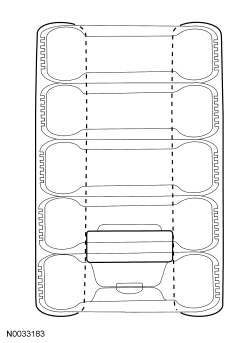
NOTE: A typical air bag disposal is shown that is similar for all vehicles.
All driver, passenger, knee and seat side air bag modules
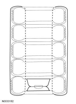
- Make a container to house the air bag module for deployment.
- NOTE: The tires must be of sufficient size to accommodate the
air bag module.
Obtain a tire and wheel assembly and an additional 4 tires (without wheels) of the same size.
- With the tire and wheel assembly on the bottom, stack the tires.
- Securely tie all of the tires together.
- NOTE: The tires must be of sufficient size to accommodate the
air bag module.

- Depower the SRS. Refer to Supplemental Restraint System (SRS) Depowering and Repowering in the General Procedures portion of this section.
- Remove the air bag module. Refer to the appropriate procedure in this section.
- NOTE: If the air bag module does not have a hard-wired pigtail,
cut the wires and connector(s) from the vehicle wire harness and reconnect
to the air bag module.
Cut each of the air bag module wires near the electrical connector that connects to the vehicle wire harness.
- Remove any sheathing (if present) and strip the insulation from the ends of the cut wires.
- NOTE: Typical driver air bag module with 2 loops shown, other air
bag modules with multiple loops or multiple features (canister vent, active
tether) similar.
For air bag modules with multiple loops, twist together a wire from each loop then repeat for the remaining wires from each loop.
- Make a jumper harness to deploy the air bag module.
- Obtain 2 wires (20 gauge minimum) at least 9.14 m (30 ft) long and strip both ends of each wire.
- At one end of the jumper harness, connect the wires together.
- Using the end of the jumper harness where the wires are not connected together, attach each wire of the jumper harness to each wire of the air bag module or to the twisted-together wires if multiple loops. Use tape or other insulating material to make sure that the leads do not make contact with each other.
Driver air bag modules
- NOTE: Make sure the air bag connections are maintained.
For driver air bag modules, with the stack of tires upright and the wheel on the bottom, carefully place the driver air bag module, with the trim cover facing up, on the wheel.
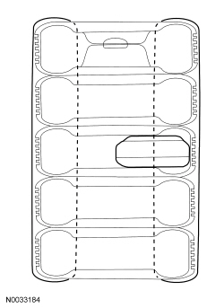
Passenger, knee and seat side air bag modules
- NOTE: Make sure the air bag connections are maintained.
Tip the stack of tires on its side and place the air bag module inside the center tire, making sure that there are 2 tires beneath the tire containing the air bag module and 2 tires (including the tire and wheel assembly) above the tire containing the air bag module.
- Place the tire stack upright, with the wheel on top.
All driver, passenger, knee and seat side air bag modules
- Remain at least 9.14 m (30 ft) away from the air bag module.
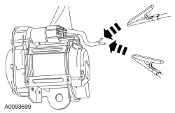
- From the end of the jumper harness that is not connected to the air bag module, disconnect the 2 wires of the jumper harness from each other.
- Deploy the air bag module by touching the ends of the 2 wires of the jumper harness to the terminals of a 12-volt battery.
- To allow for cooling, wait at least 10 minutes before approaching the deployed air bag module.
- Dispose of the deployed air bag module in the same manner as any other part to be scrapped.
Safety Belt Anchor Pretensioners, Safety Belt Buckle Pretensioners, Safety Belt Retractor Pretensioners, Adaptive Load Limiting Safety Belt Retractors and Safety Belt Inflators - Remote Deployment
WARNING: Never disassemble or tamper with seat belt deployable components, including pretensioners, load limiters and inflators. Never back probe deployable device electrical connectors. Tampering or back probing may cause an accidental deployment and result in personal injury or death.
WARNING: Deploy all supplemental restraint system (SRS) devices (airbags, pretensioners, load limiters, etc.) outdoors with all personnel at least 9 meters (30 feet) away to make sure of personal safety. Due to the loud report which occurs when an SRS device is deployed, hearing protection is required. Failure to follow these instructions may result in serious personal injury.
NOTE: A typical safety belt buckle, retractor and inflator disposal is shown that is similar for all vehicles.
- Make a container to house the safety belt buckle or retractor for
deployment.
- NOTE: The tires must be of sufficient size to accommodate the
safety belt buckle, retractor or inflator.
Obtain a tire and wheel assembly and 4 additional tires (without wheels) of the same size.
- With the tire and wheel assembly on the bottom, stack the tires.
- Securely tie all of the tires together.
- NOTE: The tires must be of sufficient size to accommodate the
safety belt buckle, retractor or inflator.
- Depower the SRS. Refer to Supplemental Restraint System (SRS) Depowering and Repowering in the General Procedures portion of this section.
- Remove the safety belt buckle, retractor or inflator. Refer to the
appropriate procedure in Section 501-20A.
- When deploying a safety belt buckle pretensioner, install a nut and bolt of sufficient length and of the same diameter as was used to retain it to the seat.
- NOTE: If the safety belt anchor, buckle, retractor or inflator
does not have a hard-wired pigtail, it will be necessary to cut the wires
and connector(s) from the vehicle wire harness and reconnect to the safety
belt buckle, retractor or inflator.
Cut each of the safety belt anchor, buckle, retractor or inflator wires near the electrical connector that connects to the vehicle wire harness.
- Remove any sheathing (if present) and strip the insulation from the ends of the cut wires.
- Make a jumper harness to deploy the safety belt buckle, retractor or
inflator.
- Obtain 2 wires (20 gauge minimum) at least 9.14 m (30 ft) long and strip both ends of each wire.
- At one end of the jumper harness, connect the wires together.
- NOTE: Typical safety belt retractor pretensioner shown, other
safety belt anchor pretensioners, buckle pretensioners, load-limiting
retractors and safety belt inflators similar.
Using the end of the jumper harness that the wires are not connected together, attach each wire of the jumper harness to each wire of the safety belt anchor, buckle, retractor or inflator. Use tape or other insulating material to make sure that the leads do not make contact with each other.
- NOTE: Make sure the safety belt anchor, buckle, retractor or
inflator connections are maintained.
Tip the stack of tires on its side and place the safety belt anchor, buckle, retractor or inflator inside the center tire, making sure that there are 2 tires beneath the tire containing the safety belt anchor, buckle, retractor or inflator and 2 tires (including the tire and wheel assembly) above the tire containing the safety belt anchor, buckle, retractor or inflator.
- Place the tire stack upright, with the wheel on top.

- Remain at least 9.14 m (30 ft) away from the safety belt anchor, buckle, retractor or inflator.
- From the end of the jumper harness that is not connected to the safety belt anchor, buckle, retractor or inflator, disconnect the 2 wires of the jumper harness from each other.
- Deploy the safety belt anchor pretensioner, buckle pretensioner, retractor pretensioner or inflator by touching the ends of the 2 wires of the jumper harness to the terminals of a 12-volt battery.
- To allow for cooling, wait at least 10 minutes before approaching the deployed safety belt anchor pretensioner, buckle pretensioner, retractor pretensioner or inflator.
- Dispose of the deployed safety belt anchor, buckle, retractor or inflator in the same manner as any other part to be scrapped.
Safety Belt Anchor Pretensioners, Safety Belt Buckle Pretensioners, Safety Belt Retractor Pretensioners and Load Limiting Safety Belt Retractors - In-Vehicle Deployment
WARNING: Never disassemble or tamper with seat belt deployable components, including pretensioners, load limiters and inflators. Never back probe deployable device electrical connectors. Tampering or back probing may cause an accidental deployment and result in personal injury or death.
WARNING: Deploy all supplemental restraint system (SRS) devices (airbags, pretensioners, load limiters, etc.) outdoors with all personnel at least 9 meters (30 feet) away to make sure of personal safety. Due to the loud report which occurs when an SRS device is deployed, hearing protection is required. Failure to follow these instructions may result in serious personal injury.
NOTE: A typical safety belt buckle and retractor disposal is shown that is similar for all vehicles.
- Depower the SRS. Refer to Supplemental Restraint System (SRS) Depowering and Repowering in the General Procedures portion of this section.
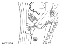
- Access the safety belt anchor, buckle or retractor electrical connectors. For additional information, refer to Section 501-20A.
- Cut each of the safety belt anchor, buckle or retractor wires, leaving at least 101.6 mm (4 in) to work with.
- Remove any sheathing (if present) and strip the insulation from the ends of the cut wires.
- Make a jumper harness to deploy the safety belt anchor, buckle or
retractor.
- Obtain 2 wires (20 gauge minimum) at least 9.14 m (30 ft) long and strip both ends of each wire.
- At one end of the jumper harness, connect the wires together.
- NOTE: Typical safety belt retractor pretensioner shown, other
safety belt anchor pretensioners, buckle pretensioners and load-limiting
retractors are similar.
Using the end of the jumper harness that the wires are not connected together, attach each wire of the jumper harness to each wire of the safety belt anchor, buckle or retractor. Use tape or other insulating material to make sure that the leads do not make contact with each other.

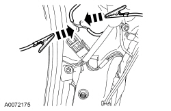
- Remain at least 9.14 m (30 ft) away from the safety belt anchor, buckle or retractor.
- From the end of the jumper harness that is not connected to the safety belt anchor, buckle or retractor, disconnect the 2 wires of the jumper harness from each other.
- Deploy the safety belt anchor pretensioner, buckle pretensioner or retractor pretensioner by touching the ends of the 2 wires of the jumper harness to the terminals of a 12-volt battery.
- To allow for cooling, wait at least 10 minutes before approaching the deployed safety belt anchor pretensioner, buckle pretensioner or retractor pretensioner.
- Dispose of the deployed safety belt anchor, buckle or retractor in the same manner as any other part to be scrapped.
Safety Canopy Modules and Side Air Curtain Modules - In-Vehicle Deployment
WARNING: Deploy all supplemental restraint system (SRS) devices (airbags, pretensioners, load limiters, etc.) outdoors with all personnel at least 9 meters (30 feet) away to make sure of personal safety. Due to the loud report which occurs when an SRS device is deployed, hearing protection is required. Failure to follow these instructions may result in serious personal injury.
NOTE: The Safety Canopy module deployment for a scrapped vehicle will occur in its installed position in the vehicle.
NOTE: A typical Safety Canopy module disposal is shown that is similar for all vehicles.
- Depower the SRS. Refer to Supplemental Restraint System (SRS) Depowering and Repowering in the General Procedures portion of this section.
- Access the Safety Canopy/side air curtain module electrical connectors. For additional information, refer to the appropriate procedure in this section.
- Cut each of the Safety Canopy/side air curtain module wires leaving at least 101.6 mm (4 in) to work with.
- Remove any sheathing (if present) and strip the insulation from the ends of the cut wires.
- NOTE: Typical Safety Canopy/side air curtain module with 2 loops
shown, other Safety Canopy/side air curtain modules with 2 loops are
similar.
For Safety Canopy/side air curtain modules with multiple loops, twist together a wire from each loop then repeat for the remaining wires from each loop.
- Make a jumper harness to deploy the Safety Canopy/side air curtain
module.
- Obtain 2 wires (20 gauge minimum) at least 9.14 m (30 ft) long and strip both ends of each wire.
- At one end of the jumper harness, connect the wires together.
- Using the end of the jumper harness where the wires are not connected together, attach each wire of the jumper harness to each wire of the Safety Canopy/side air curtain module or to the twisted-together wires if multiple loops. Use tape or other insulating material to make sure that the leads do not make contact with each other.
- From the end of the jumper harness that is not connected to the Safety Canopy/side air curtain module, disconnect the 2 wires of the jumper harness from each other.
- Deploy the Safety Canopy/side air curtain module by touching the ends of the 2 wires of the jumper harness to the terminals of a 12-volt battery.
- To allow for cooling, wait at least 10 minutes before approaching the deployed Safety Canopy/side air curtain module.
- Dispose of the deployed Safety Canopy/side air curtain module in the same manner as any other part to be scrapped.
Deployable Steering Column - In-Vehicle Deployment
WARNING: Deploy all supplemental restraint system (SRS) devices (airbags, pretensioners, load limiters, etc.) outdoors with all personnel at least 9 meters (30 feet) away to make sure of personal safety. Due to the loud report which occurs when an SRS device is deployed, hearing protection is required. Failure to follow these instructions may result in serious personal injury.
- Depower the SRS. Refer to Supplemental Restraint System (SRS) Depowering and Repowering in the General Procedures portion of this section.
- NOTE: It may be necessary to lower or remove the deployable
steering column from the instrument panel to access the deployable steering
column electrical connector.
Access the deployable steering column electrical connector.
- NOTE: If the deployable steering column does not have a
hard-wired pigtail, it will be necessary to cut the wires and connector(s)
from the vehicle wire harness and reconnect to the deployable steering
column.
Cut each of the deployable steering column wires, leaving at least 101.6 mm (4 in) to work with.
- Remove any sheathing (if present) and strip the insulation from the ends of the cut wires.
- Make a jumper harness to deploy the deployable steering column.
- Obtain 2 wires (20 gauge minimum) at least 9.14 m (30 ft) long and strip both ends of each wire.
- At one end of the jumper harness, connect the wires together.
- Using the end of the jumper harness where the wires are not connected together, attach each wire of the jumper harness to each wire of the deployable steering column. Use tape or other insulating material to make sure that the leads do not make contact with each other.
- Remain at least 9.14 m (30 ft) away from the deployable steering column.
- From the end of the jumper harness that is not connected to the deployable steering column, disconnect the 2 wires of the jumper harness from each other.
- Deploy the deployable steering column by touching the ends of the 2 wires of the jumper harness to the terminals of a 12-volt battery.
- To allow for cooling, wait at least 10 minutes before approaching the deployed steering column.
- Dispose of the deployed steering column in the same manner as any other part to be scrapped.
 Diagnosis and Testing
Airbag and Safety Belt Pretensioner Supplemental Restraint System (SRS)
DTC Charts
The DTCs can be retrieved from the RCM and the OCSM with a scan tool via
the DLC.
Restraint ...
 Removal and Installation
Clockspring
Removal and Installation
WARNING: If
the clockspring is not correctly centralized, it may fail prematurely. If in
doubt, repeat the centralizing procedure. Failure to follow these ...
Other materials:
Sensing system
WARNING: To help avoid personal injury, please read and
understand the limitations of the system as contained in this
section. Sensing is only an aid for some (generally large and fixed)
objects when moving in reverse on a flat surface at parking speeds.
Traffic control systems, inclement weat ...
Parking Aid - Visual
SPECIFICATIONS
General Specifications
DESCRIPTION AND OPERATION
Parking Aid
Component Location
Overview
The video camera system visually aids the driver while reversing or reverse
parking the vehicle. For police package vehicles, the image of the area behind
the vehicle is displayed in the LH s ...
Getting assistance outside the u.S. And canada
Before exporting your vehicle to a foreign country, contact the
appropriate foreign embassy or consulate. These officials can inform you
of local vehicle registration regulations and where to find unleaded fuel.
If you cannot find unleaded fuel or can only get fuel with an anti-knock
index low ...
