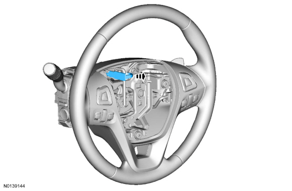
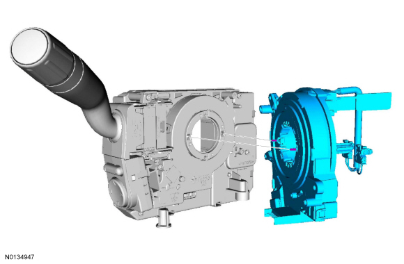
Clockspring
Removal and Installation
WARNING: If the clockspring is not correctly centralized, it may fail prematurely. If in doubt, repeat the centralizing procedure. Failure to follow these instructions may increase the risk of serious personal injury or death in a crash.
NOTE: Removal steps in this procedure may contain installation details.
All vehicles
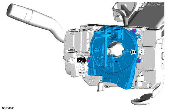
- NOTICE: If installing a new clockspring, do not remove the
clockspring anti-rotation key until the steering wheel is installed. If the
anti-rotation key has been removed before installing the steering wheel, the
clockspring must be centered. Failure to follow this instruction may result
in component damage and/or system failure.
Remove the steering wheel and the upper and lower steering column shrouds. Refer to Section 211-04.
- To install, remove the anti-rotation key from a new clockspring after installing the steering wheel.
Vehicles with active park assist
- If equipped with steering wheel rotation sensor.

- If equipped with steering wheel rotation sensor.
All vehicles
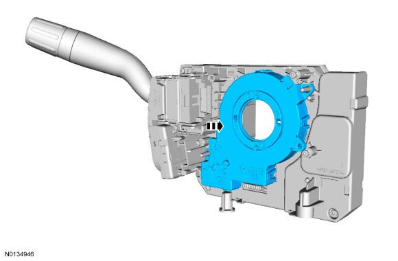
- To install, reverse the removal procedure.
Vehicles with active park assist
- If equipped with steering wheel rotation sensor.
All vehicles
- If a new clockspring was installed and the anti-rotation key has been removed before the steering wheel is installed or the clockspring being installed has rotated from its centralized position, refer to Clockspring Adjustment.
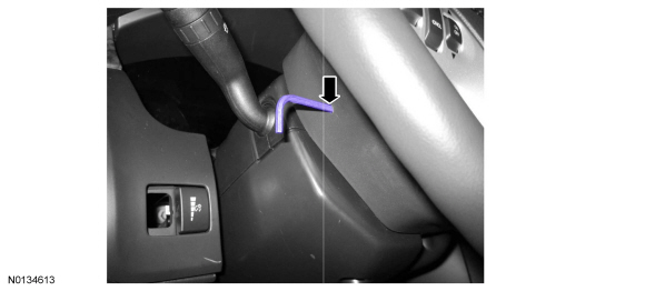
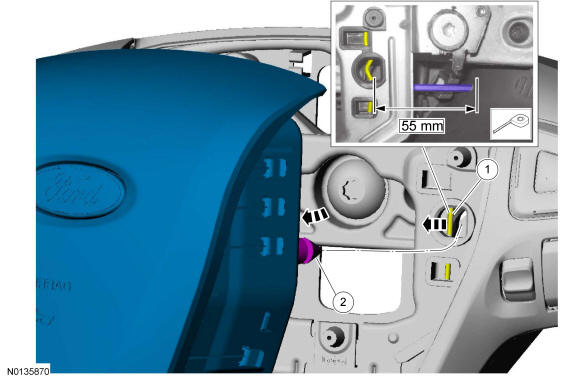
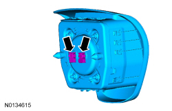
Driver Airbag
Removal
WARNING: Always carry a live airbag with the deployment door, trim cover or tear seam pointed away from the body. Do not place a live airbag down with the deployment door, trim cover or tear seam facing down. Failure to follow these instructions may result in serious personal injury in the event of an accidental deployment.
WARNING: Never probe the electrical connectors on airbag, Safety Canopy or side air curtain assemblies. Failure to follow this instruction may result in the accidental deployment of these assemblies, which increases the risk of serious personal injury or death.
WARNING: Do not paint any airbag trim covers or deployment doors. Paint may cause the airbag to deploy incorrectly. Failure to follow this instruction may increase the risk of serious personal injury or death in a crash.
- Depower the SRS. Refer to Supplemental Restraint System (SRS) Depowering and Repowering.
- 3mm (.118 in) Allen key.
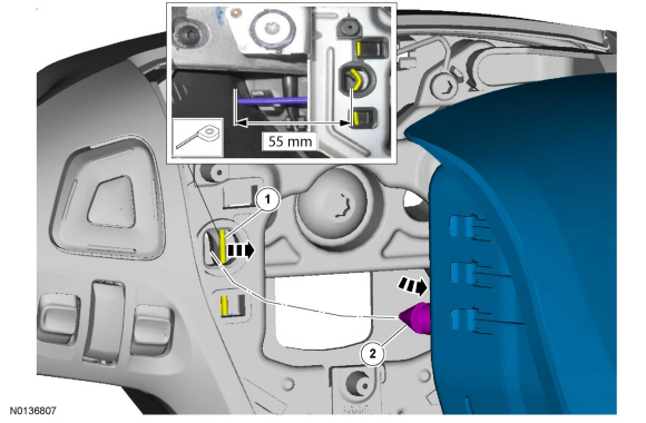
- 3mm (.118 in) Allen key.
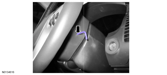
Installation

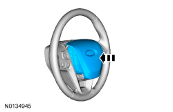
- Repower the SRS. Refer to Supplemental Restraint System (SRS) Depowering and Repowering.
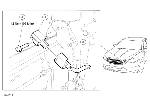
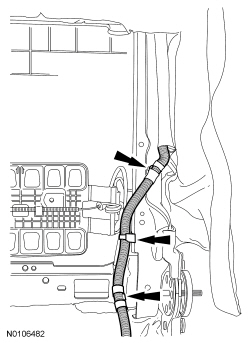
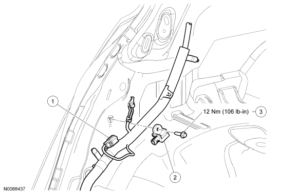
Front Impact Severity Sensor
NOTE: LH shown, RH similar.
WARNING: If a vehicle has been in a crash, inspect the restraints control module (RCM) and the impact sensor (if equipped) mounting areas for deformation. If damaged, restore the mounting areas to the original production configuration. A new RCM and sensors must be installed whether or not the airbags have deployed. Failure to follow these instructions may result in serious personal injury or death in a crash.
NOTE: Always make sure the correct SRS component is being installed. Parts released for other vehicles may not be compatible even if they appear physically similar. Check the part number listed in the Ford Catalog Advantage or equivalent to make sure the correct component is being installed. If an incorrect SRS component is installed, DTCs may set.
NOTE: Removal steps in this procedure may contain installation detail.
- Depower the SRS. Refer to Supplemental Restraint System (SRS) Depowering and Repowering.
- NOTE: Index mark the CAC tube for installation.
For the RH side and vehicles equipped with a 3.5L Gasoline Turbocharged Direct Injection (GTDI) engine, remove the CAC tube.
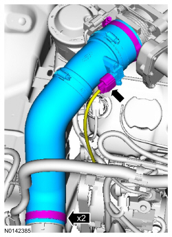
- For the LH side, remove the Air Cleaner (ACL). Refer to Section 303-12.
- WARNING:
Always tighten the fasteners of the restraints control module (RCM) and
impact sensor (if equipped) to the specified torque. Failure to do so may
result in incorrect restraint system operation, which increases the risk of
personal injury or death in a crash.
NOTE: Make sure the front impact severity sensor and mating surfaces are clean and free of foreign material.
Remove the bolt, disconnect the electrical connector and remove front impact severity sensor.- To install, tighten to 12 Nm (106 lb-in).
- To install, reverse the removal procedure.
- Repower the SRS. Refer to Supplemental Restraint System (SRS) Depowering and Repowering.
Passenger Airbag
Removal and Installation
WARNING: Always carry a live airbag with the deployment door, trim cover or tear seam pointed away from the body. Do not place a live airbag down with the deployment door, trim cover or tear seam facing down. Failure to follow these instructions may result in serious personal injury in the event of an accidental deployment.
WARNING: Never probe the electrical connectors on airbag, Safety Canopy or side air curtain assemblies. Failure to follow this instruction may result in the accidental deployment of these assemblies, which increases the risk of serious personal injury or death.
NOTE: The air bag warning indicator illuminates when the correct Restraints Control Module (RCM) fuse is removed and the ignition is ON.
NOTE: The Supplemental Restraint System (SRS) must be fully operational and free of faults before releasing the vehicle to the customer.
- Depower the SRS. For additional information, refer to Supplemental Restraint System (SRS) Depowering and Repowering in this section.
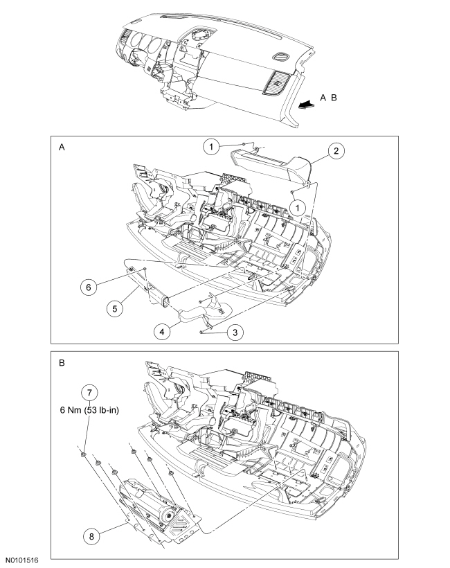
- Remove the instrument panel upper section. For additional information, refer to Section 501-12.
- Remove the screws and ventilation duct.
- Remove the screws and defroster ducts.
- Remove the 6 nuts and passenger air bag module.
- To install, tighten to 6 Nm (53 lb-in).
- To install, reverse the removal procedure.
- Repower the SRS. For additional information, refer to Supplemental Restraint System (SRS) Depowering and Repowering in this section.
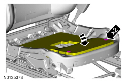
Occupant Classification Sensor
Removal
Seat with weight sensor bolt OCS
- NOTE: The OCS is part of the front passenger seat track assembly
and is not serviced separately.
Remove the front passenger seat track. Refer to Section 501-10.
Seat with bladder OCS
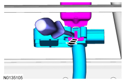
NOTICE: To prevent system failure, it is necessary to carry out the OCS reset when a front passenger seat cushion is disassembled, a new seat cushion cover installed or an OCS service kit is installed. A scan tool is used to carry out the OCS reset.
NOTE: An OCS service kit has the electrical connector glued to the OCSM. It cannot and should not be disconnected or altered.
- Remove the front passenger seat cushion cover. Refer to Section 501-10.
- If equipped with heated seat.


Installation
- WARNING:
Occupant Classification System (OCS) parts are calibrated as an assembly and
must only be replaced in the configuration they are sold. Never separate
parts of an assembly. Failure to follow this instruction may result in
incorrect operation of the passenger airbag and increases the risk of
serious personal injury or death in a crash.
NOTICE: Failure to correctly route the OCS components may cause component failure and incorrect operation of the OCS.
- If equipped with heated seat.
- Install the front passenger seat cushion cover. Refer to Section 501-10.
- Repower the SRS. Do not prove out the SRS at this time. Refer to Supplemental Restraint System (SRS) Depowering and Repowering.
- Carry out OCS reset. Refer to Occupant Classification Sensor (OCS) System Reset.
- NOTE: A prepaid return postcard is provided with a
new OCS service kit. The serial number for the new part and the VIN must be
recorded and sent to Ford Motor Company.
If a new OCS service kit was installed, fill out the necessary information on the OCS traceability card and return it along with the complete inoperative OCS to Ford Motor Company.
- When returning the inoperative OCS, include: foam pad, bladder, pressure sensor and hose.
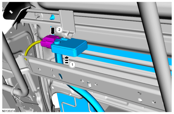
Occupant Classification System Module (OCSM)
NOTE: This procedure only applies to seats equipped with Occupant Classification System (OCS) weight sensor bolts.
Removal
WARNING: Turn the ignition OFF and wait one minute to deplete the backup power supply. Failure to follow this instruction may result in serious personal injury or death in the event of an accidental deployment.
NOTE: The Supplemental Restraint System (SRS) must be fully operational and free of faults before releasing the vehicle to the customer.
- Turn the ignition OFF and wait one minute.
- Raise the seat to its highest position.
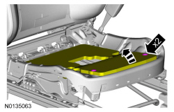
- Disconnect the Occupant Classification System Module (OCSM) electrical connector.
- Remove the 2 screws and OCSM.
- To install, reverse the removal procedure.
- Carry out OCS system reset. For additional information, refer to Occupant Classification Sensor (OCS) System Reset in this section.
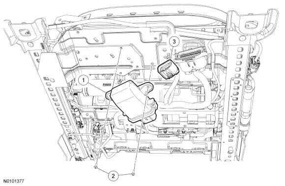
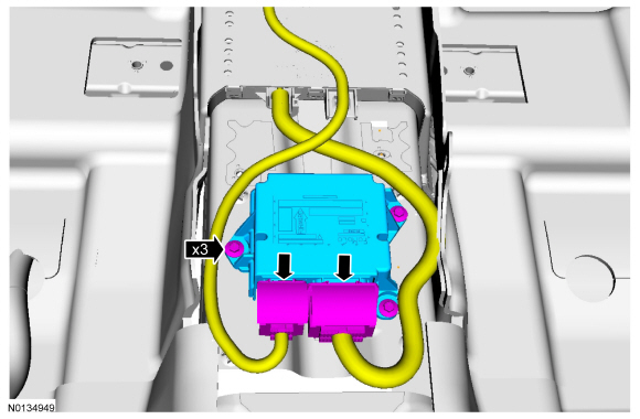
Restraints Control Module (RCM)
Removal
WARNING: If a vehicle has been in a crash, inspect the restraints control module (RCM) and the impact sensor (if equipped) mounting areas for deformation. If damaged, restore the mounting areas to the original production configuration. A new RCM and sensors must be installed whether or not the airbags have deployed. Failure to follow these instructions may result in serious personal injury or death in a crash.
WARNING: Do not handle, move or change the original horizontal mounting position of the restraints control module (RCM) while the RCM is connected and the ignition switch is ON. Failure to follow this instruction may result in the accidental deployment of the Safety Canopy and cause serious personal injury or death.
NOTE: Always make sure the correct SRS component is being installed. Parts released for other vehicles may not be compatible even if they appear physically similar. Check the part number listed in the Master Parts Catalog to make sure the correct component is being installed. If an incorrect SRS component is installed, DTCs may set.
NOTE: Carrying out PMI will not enable the 911 assist option that is disabled. The RCM and APIM must be configured correctly to fully support 911 assist functionality.
- Carry out the steps necessary to prepare for PMI. Refer to Section 418-01.
- Depower the SRS. Refer to Supplemental Restraint System (SRS) Depowering and Repowering.
- Remove the floor console. Refer to Section 501-12.
- WARNING:
Always tighten the fasteners of the restraints control module (RCM) and
impact sensor (if equipped) to the specified torque. Failure to do so may
result in incorrect restraint system operation, which increases the risk of
personal injury or death in a crash.
12 Nm (106 lb-in)
Installation
- To install, reverse the removal procedure.
- Repower the SRS. Refer to Supplemental Restraint System (SRS) Depowering and Repowering.
- If a new RCM was installed, carry out the appropriate steps to complete the PMI procedure. Refer to Section 418-01.
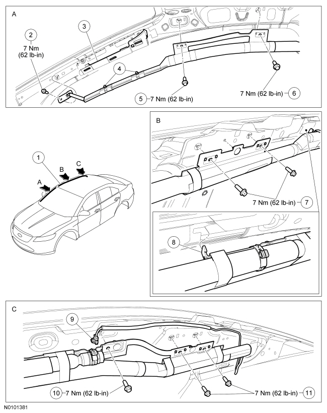
Safety Canopy
NOTE: RH shown, LH similar.
Removal
WARNING: Always carry a live Safety Canopy or side air curtain assembly with the tear seam pointed away from your body. Failure to follow this instruction may result in serious personal injury or death in the event of an accidental deployment.
WARNING: Anytime the Safety Canopy or side air curtain module has deployed, a new headliner and new A-, B- and C-pillar upper trim panels and attaching hardware must be installed. Remove any other damaged components and hardware and install new components and hardware as needed. Failure to follow these instructions may result in the Safety Canopy or side air curtain module deploying incorrectly and increases the risk of serious personal injury or death in a crash.
WARNING: Never probe the electrical connectors on airbag, Safety Canopy or side air curtain assemblies. Failure to follow this instruction may result in the accidental deployment of these assemblies, which increases the risk of serious personal injury or death.
NOTE: The air bag warning indicator illuminates when the correct Restraints Control Module (RCM) fuse is removed and the ignition is ON.
NOTE: The Supplemental Restraint System (SRS) must be fully operational and free of faults before releasing the vehicle to the customer.
- Depower the SRS. For additional information, refer to Supplemental Restraint System (SRS) Depowering and Repowering in this section.
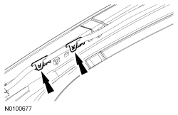
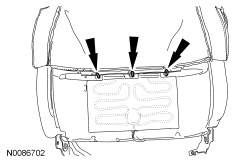
- Remove the 3 passenger assist handles.
- If equipped, disconnect the electrical connectors.
- Remove the A-pillar trim panels. For additional information, refer to Section 501-05.
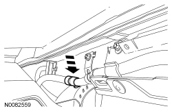
- NOTE: RH shown, LH similar.
Disconnect the 4 A-pillar wiring retainer clips.
- Remove the B-pillar trim panels. For additional information, refer to Section 501-05.
- Remove the C-pillar trim panels. For additional information, refer to Section 501-05.
- Remove the overhead console.
- Disconnect the electrical connectors.
- If equipped, disconnect the automatic-dimming rear view mirror electrical connector.
- Remove the sun visors and sun visor clips.
- If equipped, disconnect the electrical connectors.
- Remove the 2 headliner pushpins at the rear.
- Remove the 2 headliner pushpins at the front.
- Disconnect the roof opening panel motor.
- If equipped, detach the roof opening panel drain hose from the A-pillar and position aside.
- Remove the bolt and Safety Canopy module front tether.
- Release the pin-type retainers.
- Disconnect the Safety Canopy module electrical connector.
- Remove the 2 Safety Canopy module bolts near the A-pillar.
- Remove the 2 Safety Canopy module bolts near the B-pillar.
- Remove the 3 Safety Canopy module bolts near the C-pillar.
- Detach the T-tab from the sheet metal and remove the Safety Canopy module.
Installation
WARNING: Before installing a Safety Canopy or side air curtain assembly, inspect the roofline for any damage. If necessary, the sheet metal must be reworked to its original condition and structural integrity. Install new fasteners if damaged and remove foreign material. Failure to follow these instructions may result in the Safety Canopy or side air curtain deploying incorrectly, which increases the risk of serious personal injury or death in a crash.
WARNING: Inspect a Safety Canopy or side air curtain module before installation. If the module is damaged, the cover has separated or the Safety Canopy or side air curtain material has been exposed, install a new module. Do not attempt to repair the module. Failure to follow these instructions may result in the Safety Canopy or side air curtain deploying incorrectly, which increases the risk of serious personal injury or death in a crash.
WARNING: Never put any type of fastener or tie strap around any part of a Safety Canopy module, side air curtain module or interior trim panel. This will prevent the Safety Canopy or side air curtain module from deploying correctly. Failure to follow this instruction may increase the risk of serious personal injury or death in a crash.
WARNING: Do not obstruct or place objects in the deployment path of the Safety Canopy or side air curtain module. Failure to follow this instruction may result in the Safety Canopy or side air curtain module deploying incorrectly and increases the risk of serious personal injury or death in a crash.
- Insert the T-tab into the sheet metal and position the Safety Canopy module.
- Install the 2 Safety Canopy module bolts near the C-pillar.
- Tighten to 7 Nm (62 lb-in).
- Install the 3 Safety Canopy module bolts near the B-pillar.
- Tighten to 7 Nm (62 lb-in).
- Install the 2 Safety Canopy module bolts near the A-pillar.
- Tighten to 7 Nm (62 lb-in).
- Install the Safety Canopy module front tether and bolt and attach the
pin-type retainers.
- Tighten to 7 Nm (62 lb-in).
- If equipped, position the roof opening panel drain hose back and attach to the A-pillar.

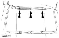
- Install the 2 headliner pushpins at the front.
- Install the 2 headliner pushpins at the rear.
- Install the sun visors and sun visor clips.
- If equipped, connect the electrical connectors.
- If equipped, connect the automatic-dimming rear view mirror electrical connector.
- Install the overhead console.
- Connect the electrical connectors.
- Install the C-pillar trim panels. For additional information, refer to Section 501-05.
- Install the B-pillar trim panels. For additional information, refer to Section 501-05.
- NOTE: RH shown, LH similar.
Connect the 4 A-pillar wiring retainer clips.

- Install the A-pillar trim panels. For additional information, refer to Section 501-05.
- Install the 3 passenger assist handles.
- If equipped, connect the electrical connectors.
- Repower the SRS. For additional information, refer to Supplemental Restraint System (SRS) Depowering and Repowering in this section.
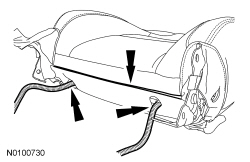
Side Airbag
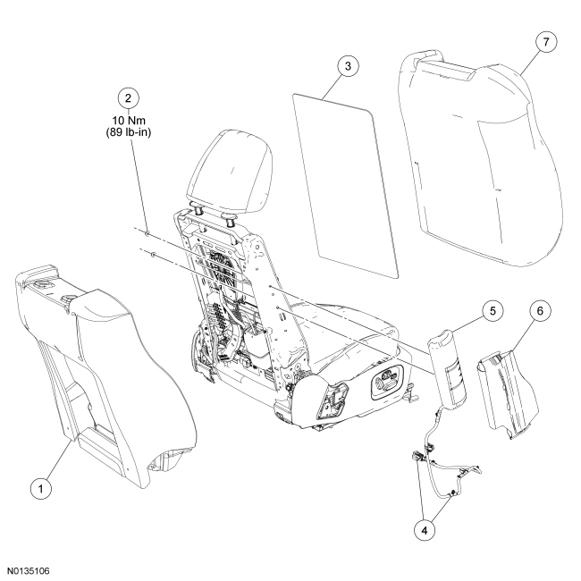
NOTE: Passenger seat shown, driver seat similar.
Removal
WARNING: Always carry a live airbag with the deployment door, trim cover or tear seam pointed away from the body. Do not place a live airbag down with the deployment door, trim cover or tear seam facing down. Failure to follow these instructions may result in serious personal injury in the event of an accidental deployment.
WARNING: Never probe the electrical connectors on airbag, Safety Canopy or side air curtain assemblies. Failure to follow this instruction may result in the accidental deployment of these assemblies, which increases the risk of serious personal injury or death.
WARNING: Front seat backrest trim covers installed on seats equipped with seat side airbags cannot be repaired. A new trim cover must be installed. Cleaning is permissible. Failure to follow these instructions may result in the seat side airbag deploying incorrectly and increase the risk of serious personal injury or death in a crash.
NOTE: If a side air bag deployment took place, a new seat backrest foam pad, backrest cover, deployment chute and side air bag module and nuts must be installed. The seat backrest frame should be replaced if necessary.
- Remove the front seat backrest. Refer to Section 501-10.
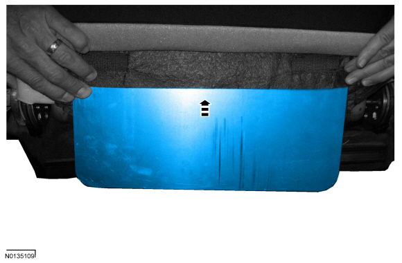
- Disengage the backrest cover lower J-clip and route the wire harness(es) and air hoses (if equipped) out of the hole(s) in the backrest cover.
- If equipped with police package.
- If equipped with police package.
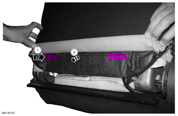
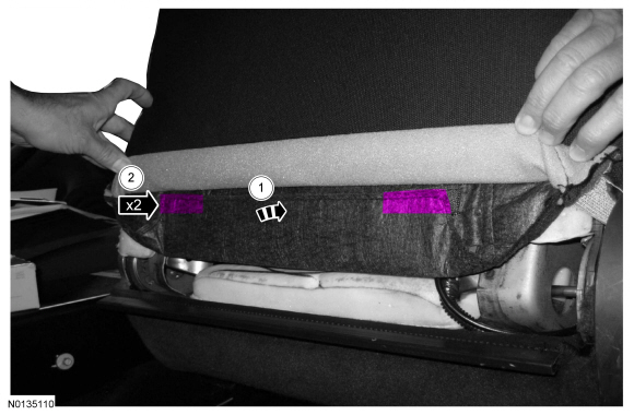
- On each side, separate the backrest cover clip and hook-and-loop strips.
- Remove the 3 first-row hog rings
- Invert the backrest cover up and remove the 3 second row hog rings.
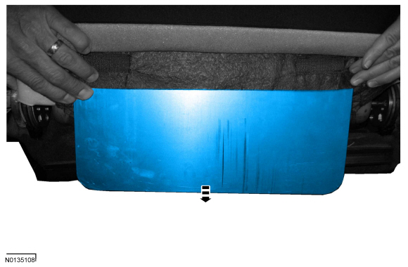
- From the rear of the backrest, disengage the backrest cover J-clip.
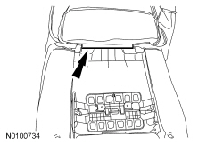
- Remove the outboard pin-type retainer.
- Disengage the side air bag module wire harness retainers from the backrest frame.
- Remove the nuts, side air bag module and wire harness.
- Remove the side air bag module from the deployment chute.
Installation
WARNING: Inspect the seat side air bag module cavity in the seat backrest foam pad for any foreign material. If any foreign material is found, remove it. Failure to follow these instructions may result in the seat side air bag module deploying incorrectly and increases the risk of serious personal injury or death in a crash.
WARNING: Before installing the seat side air bag module/deployment chute assembly:
- Inspect the side air bag module and mounting surfaces for any damage or foreign material.
- Remove any foreign material from the mounting surfaces of the deployment chute, the seat backrest frame mounting bracket and the air bag module cavity in the seat backrest foam pad.
- Install new parts if damaged.
WARNING: If the seat side airbag cover has been damaged or separated from its mounting, or if the airbag material has been exposed, install a new seat side airbag assembly. Never try to repair the seat side airbag assembly. Failure to follow these instructions may result in the seat side airbag deploying incorrectly, which increases the risk of serious personal injury or death in a crash.
NOTICE: Make sure the side air bag module wiring harness is not pinched between the side air bag module and the backrest frame. Failure to follow this instruction may result in component damage and/or system failure.
- WARNING:
Before installing the seat side air bag module/deployment chute assembly:
- Inspect the side air bag module and mounting surfaces for any damage or foreign material.
- Remove any foreign material from the mounting surfaces of the deployment chute, the seat backrest frame mounting bracket and the air bag module cavity in the seat backrest foam pad.
- Install new parts if damaged.
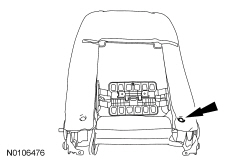
NOTE: Passenger side shown, driver side similar.
Position the side air bag module into the deployment chute.- Route the side air bag module wire harness through the deployment chute.
- Position the 2 side air bag module studs and locator pin through the deployment chute holes.
- WARNING:
Inspect the seat side air bag module cavity in the seat backrest foam pad
for any foreign material. If any foreign material is found, remove it.
Failure to follow these instructions may result in the seat side air bag
module deploying incorrectly and increases the risk of serious personal
injury or death in a crash.
NOTE: The side air bag modules are keyed left and right. If the side air bag module locator pin does not align to the backrest frame hole, the wrong side air bag module is being installed.
Position the 2 side air bag module studs and locator pin through the backrest frame and install the 2 nuts.- Tighten to 10 Nm (89 lb-in).

- Route and attach the side air bag module wire harness to the backrest frame.

- Install the pin-type retainer on the side of the side air bag module.
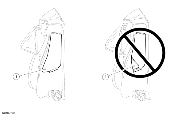
- WARNING:
If the seat side air bag module deployment chute is not correctly
positioned, the seat side air bag may not deploy correctly. Failure to
follow this instruction may result in the seat side air bag deploying
incorrectly, which increases the risk of serious personal injury or death in
a crash.
Check the position of the deployment chute.
- Position both deployment chute front edges to lay flat, from top to bottom, between the backrest foam pad and backrest frame.
- Do not allow the deployment chute front edges to fold over, at any point, between the backrest foam pad and backrest frame.
- Roll the backrest cover down and install the 3 second row hog rings.

- Install the 3 first-row hog rings.

- If equipped with police package.
- If equipped with police package.
- Route the wire harness(es) and air hoses (if equipped) through the
hole(s) in the backrest cover and engage the lower J-clips.
- Make sure the manual lumbar cable is routed out from the outboard side of the backrest before engaging the lower J-clips (if equipped).
- On each side, wrap the backrest cover around the recliner and attach the hook-and-loop strips and clip.
- Install the front seat backrest. Refer to Section 501-10.
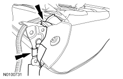
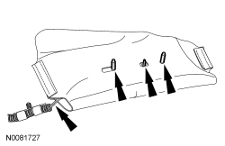
Side Impact Sensor - Front Door
NOTE: LH shown, RH similar.
WARNING: If a vehicle has been in a crash, inspect the restraints control module (RCM) and the impact sensor (if equipped) mounting areas for deformation. If damaged, restore the mounting areas to the original production configuration. A new RCM and sensors must be installed whether or not the airbags have deployed. Failure to follow these instructions may result in serious personal injury or death in a crash.
NOTE: Always make sure the correct Supplemental Restraint System (SRS) component is being installed. Parts released for other vehicles may not be compatible even if they appear physically similar. Check the part number listed in the Master Parts Catalog to make sure the correct component is being installed. If an incorrect SRS component is installed, DTCs may set.
NOTE: The air bag warning indicator illuminates when the correct Restraints Control Module (RCM) fuse is removed and the ignition is ON.
NOTE: The SRS must be fully operational and free of faults before releasing the vehicle to the customer.
- Depower the SRS. For additional information, refer to Supplemental Restraint System (SRS) Depowering and Repowering in this section.
- Remove the front door trim panel. For additional information, refer to Section 501-05.
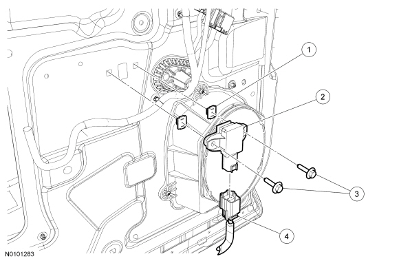
- Disconnect the side impact sensor (pressure sensor) electrical connector.
- NOTICE: To prevent stripping the insert nuts, tighten the side
impact sensor bolts only enough to retain the side impact sensor (pressure
sensor) correctly.
Remove the 2 bolts and side impact sensor (pressure sensor).
- NOTE: Before installing the bolts, inspect the inserts nuts for
damage. If damaged, install a new insert nut.
To install, reverse the removal procedure.
- Repower the SRS. For additional information, refer to Supplemental Restraint System (SRS) Depowering and Repowering in this section.
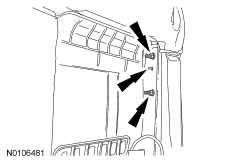
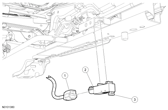
Side Impact Sensor - Second Row, C-Pillar
NOTE: RH shown, LH similar.
WARNING: If a vehicle has been in a crash, inspect the restraints control module (RCM) and the impact sensor (if equipped) mounting areas for deformation. If damaged, restore the mounting areas to the original production configuration. A new RCM and sensors must be installed whether or not the airbags have deployed. Failure to follow these instructions may result in serious personal injury or death in a crash.
NOTE: Always make sure the correct Supplemental Restraint System (SRS) component is being installed. Parts released for other vehicles may not be compatible even if they appear physically similar. Check the part number listed in the Master Parts Catalog to make sure the correct component is being installed. If an incorrect SRS component is installed, DTCs may set.
NOTE: Removal steps in this procedure may contain installation detail.
- Depower the SRS. Refer to Supplemental Restraint System (SRS) Depowering and Repowering.
- Remove the rear seat bolster. Refer to Section 501-10.
- Disconnect the side impact sensor electrical connector.
- Remove the bolt and side impact sensor.
- To install, tighten to 12 Nm (106 lb-in).
- WARNING:
Always tighten the fasteners of the restraints control module (RCM) and
impact sensor (if equipped) to the specified torque. Failure to do so may
result in incorrect restraint system operation, which increases the risk of
personal injury or death in a crash.
NOTE: Make sure the C-pillar and side impact sensor mating surfaces are clean and free of foreign material.
To install, reverse the removal procedure.
- Repower the SRS. Refer to Supplemental Restraint System (SRS) Depowering and Repowering.
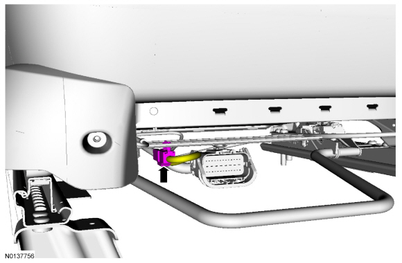
Seat Position Sensor
NOTE: RH shown, LH similar.
NOTE: Manual seat shown, power seat similar.
NOTE: Ignition must be OFF if disconnecting the seat position sensor electrical connector. Otherwise, a DTC will be set in the Restraints Control Module (RCM) memory and must be cleared before releasing the vehicle.
NOTE: The air bag warning indicator illuminates when the correct RCM fuse is removed and the ignition is ON.
NOTE: The Supplemental Restraint System (SRS) must be fully operational and free of faults before releasing the vehicle to the customer.
- WARNING:
Turn the ignition OFF and wait one minute to deplete the backup power
supply. Failure to follow this instruction may result in serious personal
injury or death in the event of an accidental deployment.
Turn the ignition OFF and wait at least one minute.
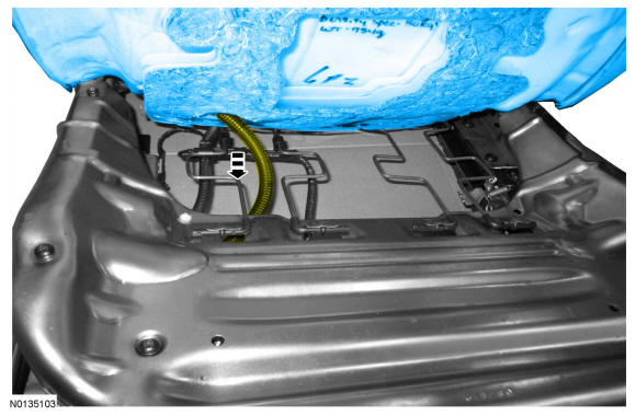
- Position the seat to the middle of its horizontal travel and all the way up.
- Disconnect the seat position sensor electrical connector.
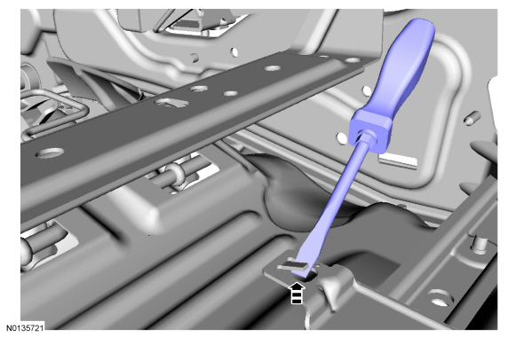
- Remove the seat track position sensor in the following sequence.
- Pull to release the lock tab.
- Slide back, disengage and remove the seat track position sensor.
- To install, reverse the removal procedure.
- Prove out the SRS as follows:
Turn the ignition from ON to OFF. Wait 10 seconds, then turn the ignition back to ON and monitor the air bag warning indicator with the air bag modules installed. The air bag warning indicator will illuminate continuously for approximately 6 seconds and then turn off. If a SRS fault is present, the air bag warning indicator will:
- fail to light.
- remain lit continuously.
- flash.
The flashing might not occur until approximately 30 seconds after the ignition has been turned from OFF to the ON position. This is the time required for the RCM to complete the testing of the SRS. If the air bag warning indicator is inoperative and a SRS fault exists, a chime will sound in a pattern of 5 sets of 5 beeps. If this occurs, the air bag warning indicator and any SRS fault discovered must be diagnosed and repaired.
Clear all continuous DTCs from the RCM and Occupant Classification System Module (OCSM) using a scan tool.
 General Procedures
Clockspring Adjustment
WARNING: If
the clockspring is not correctly centralized, it may fail prematurely. If in
doubt, repeat the centralizing procedure. Failure to follow these instructions
...
 Body Repairs
...
Other materials:
Removal and Installation
Generator - 2.0L GTDI
Removal
Disconnect the battery. For additional information, refer to Section
414-01.
Remove the upper Charge Air Cooler (CAC) pipe. For additional
information, refer to Intake Air System Components - Exploded View
in Section 303-12.
...
Starting a gasoline engine
When you start the engine, the idle speed increases, this helps to warm
up the engine. If the engine idle speed does not slow down automatically,
have your vehicle checked by an authorized dealer.
Note: You can crank the engine for a total of 60 seconds (without the
engine starting) before the ...
Fuel Tank and Lines
SPECIFICATIONS
General Specifications
Torque Specifications
DESCRIPTION AND OPERATION
Fuel Tank and Lines
2.0L Gasoline Turbocharged Direct Injection (GTDI)
Fuel Tank and Lines
The fuel tank and lines consists of:
a single container (L-shaped) fuel tank.
a fuel level sensor assembly.
a Fuel ...
