Airbag and Safety Belt Pretensioner Supplemental Restraint System (SRS)
DTC Charts
The DTCs can be retrieved from the RCM and the OCSM with a scan tool via the DLC.
Restraints Control Module (RCM) DTC ChartNOTE: Always make sure the correct SRS component is being installed. Parts released for other vehicles may not be compatible even if they appear physically similar. Check the part number listed in the parts catalog to make sure the correct component is being installed. If an incorrect SRS component is installed, DTCs may set.
NOTE: Diagnostics in this manual assume a certain skill level and knowledge of Ford-specific diagnostic practices. REFER to Diagnostic Methods in Section 100-00 for information about these practices.
Occupant Classification System Module (OCSM) DTC Chart - Bladder System
NOTE: Always make sure the correct SRS component is being installed. Parts released for other vehicles may not be compatible even if they appear physically similar. Check the part number listed in the parts catalog to make sure the correct component is being installed. If an incorrect SRS component is installed, DTCs may set.
NOTE: Diagnostics in this manual assume a certain skill level and knowledge of Ford-specific diagnostic practices. REFER to Diagnostic Methods in Section 100-00 for information about these practices.
Occupant Classification System Module (OCSM) DTC Chart - Weight Sensor Bolt System
NOTE: Always make sure the correct SRS component is being installed. Parts released for other vehicles may not be compatible even if they appear physically similar. Check the part number listed in the parts catalog to make sure the correct component is being installed. If an incorrect SRS component is installed, DTCs may set.
NOTE: Diagnostics in this manual assume a certain skill level and knowledge of Ford-specific diagnostic practices. REFER to Diagnostic Methods in Section 100-00 for information about these practices.
Front Controls Interface Module (FCIM) DTC Chart
NOTE: Always make sure the correct SRS component is being installed. Parts released for other vehicles may not be compatible even if they appear physically similar. Check the part number listed in the parts catalog to make sure the correct component is being installed. If an incorrect SRS component is installed, DTCs may set.
NOTE: Diagnostics in this manual assume a certain skill level and knowledge of Ford-specific diagnostic practices. REFER to Diagnostic Methods in Section 100-00 for information about these practices.

Symptom Chart
NOTE: Diagnostics in this manual assume a certain skill level and knowledge of Ford-specific diagnostic practices. REFER to Diagnostic Methods in Section 100-00 for information about these practices.
Pinpoint Test
Pinpoint Test A: DTCs B0001:11, B0001:12, B0001:13 and B0001:1A
Diagnostic Overview
Diagnostics in this manual assume a certain skill level and knowledge of Ford-specific diagnostic practices. Refer to Diagnostic Methods in Section 100-00 for information about these practices.
Refer to Wiring Diagrams Cell 46, Supplemental Restraint System for schematic and connector information.
Normal Operation and Fault Conditions
The RCM continuously monitors the driver air bag module stage 1 and circuits for the following faults:
- Resistance out of range
- Unexpected voltage
- Short to ground
- Faulted driver air bag module
If a fault is detected, the RCM stores DTC B0001:11, B0001:12, B0001:13 or B0001:1A in memory and sends a message to the IPC to illuminate the air bag warning indicator.
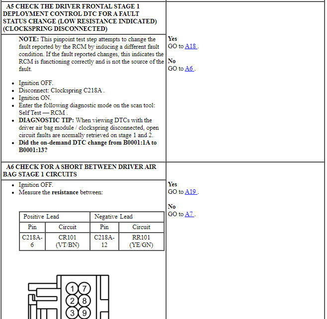
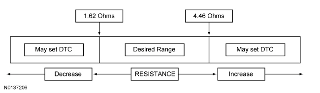
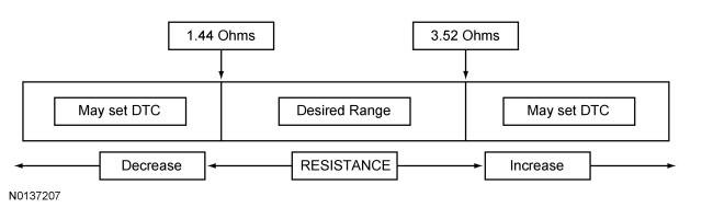
The RCM analyzes the deployment loop resistance to determine if a fault exists. The value displayed in the PID is the deployment loop resistance measured by the RCM. If the value displayed is lower or higher than the desired range (refer to diagram below), the RCM can set a DTC. As the deployment loop resistance drifts farther outside the desired range, the chance for a DTC increases. Small variations in resistance can occur due to the effect of road vibrations on terminal fit. Crimps and terminals can be affected by stress and harness movement and can cause an increase in resistance due to wire strain. These variables can result in an intermittent fault. For this reason, the test requires the PID value to be within the desired range before the fault is considered repaired, regardless if the module is reporting an on-demand DTC at the time of diagnosis. Following this direction helps make sure that minor changes in resistance do not create a repeat concern. This test uses process of elimination to diagnose each part of the deployment loop circuit including:
- Wiring
- Connections
- Clockspring
- Driver air bag module
- RCM

-
Visual Inspection and Diagnostic Pre-checks
- Inspect for damaged wiring harness(es).
- Inspect for loose or damaged connectors.
-
Possible Sources
- Wiring, terminals or connectors
- Clockspring
- Driver air bag module
- RCM
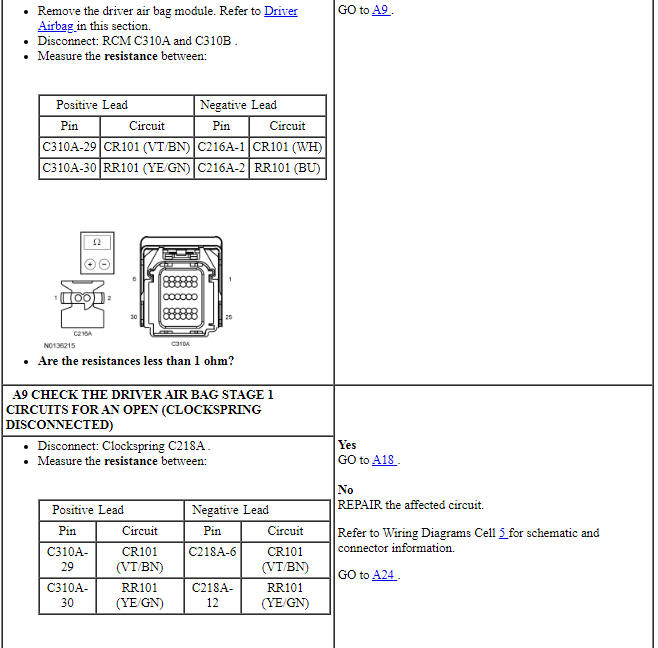
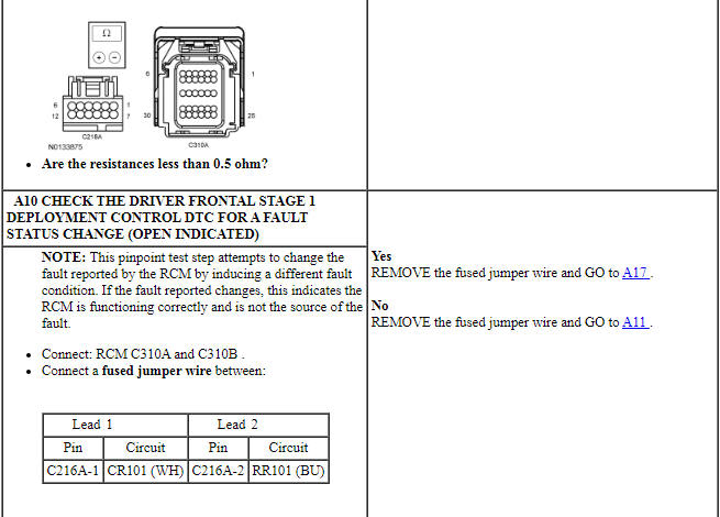
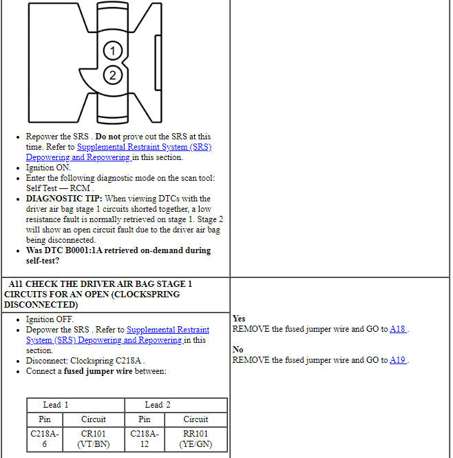
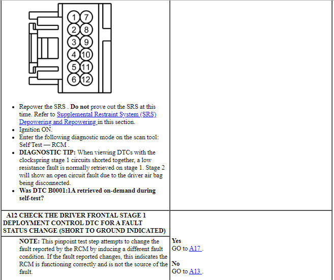
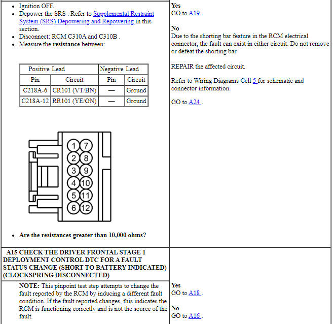
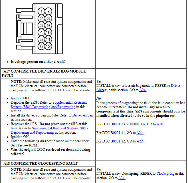
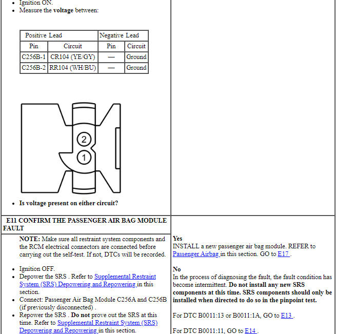
PINPOINT TEST A: DTCs B0001:11, B0001:12, B0001:13 AND B0001:1A
WARNING: Do not handle, move or change the original horizontal mounting position of the restraints control module (RCM) while the RCM is connected and the ignition switch is ON. Failure to follow this instruction may result in the accidental deployment of the Safety Canopy and cause serious personal injury or death.
WARNING: Never probe the electrical connectors on airbag, Safety Canopy or side air curtain assemblies. Failure to follow this instruction may result in the accidental deployment of these assemblies, which increases the risk of serious personal injury or death.
NOTICE: Use the correct probe adapter(s) from the Flex Probe Kit when taking measurements. Failure to use the correct probe adapter(s) may damage the connector.
NOTE: Most faults are due to connector and/or wiring concerns. Carry out a thorough inspection and verification before proceeding with the pinpoint test.
NOTE: Only disconnect or reconnect SRS components when instructed to do so within a pinpoint test step. Failure to follow this instruction may result in incorrect diagnosis of the SRS.
NOTE: Always make sure the correct SRS component is being installed. Parts released for other vehicles may not be compatible even if they appear physically similar. Check the part number listed in the parts catalog to make sure the correct component is being installed. If an incorrect SRS component is installed, DTCs may set.
NOTE: The SRS must be fully operational and free of faults before releasing the vehicle to the customer.
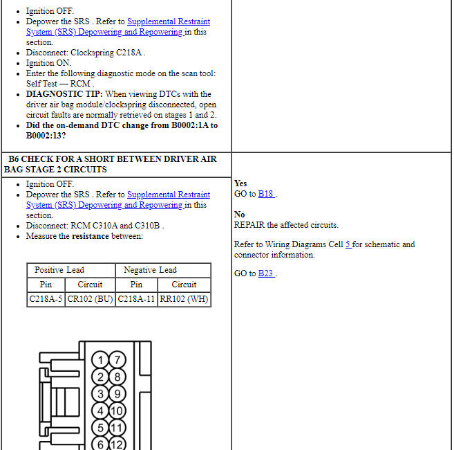
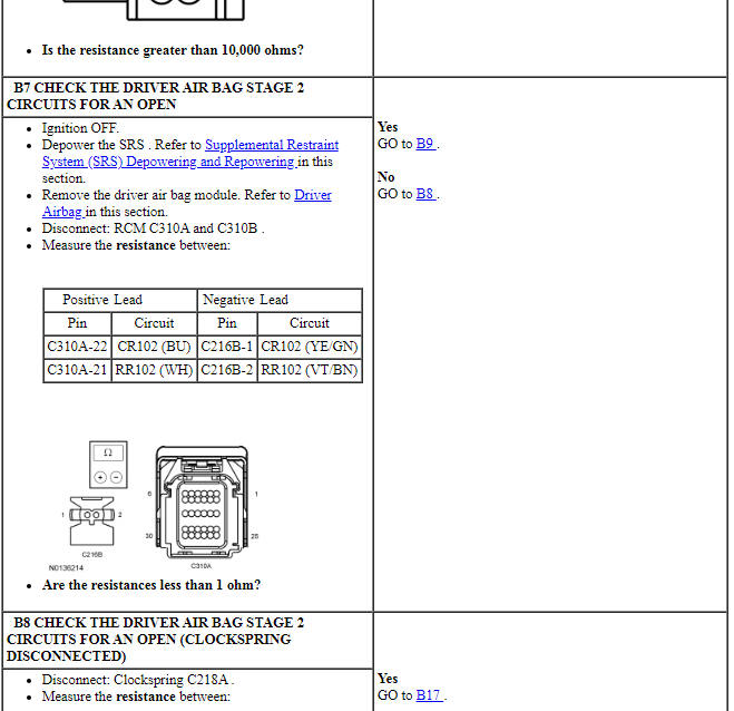
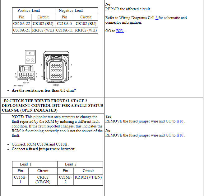
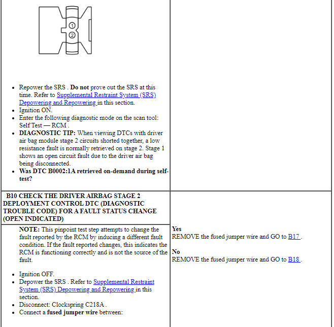
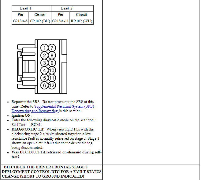
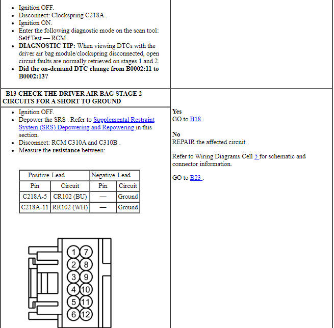
Pinpoint Test B: DTCs B0002:11, B0002:12, B0002:13 and B0002:1A
Diagnostic Overview
Diagnostics in this manual assume a certain skill level and knowledge of Ford-specific diagnostic practices. Refer to Diagnostic Methods in Section 100-00 for information about these practices.
Refer to Wiring Diagrams Cell 46, Supplemental Restraint System for schematic and connector information.
Normal Operation and Fault Conditions
The RCM continuously monitors the driver air bag module stage 2 and circuits for the following faults:
- Resistance out of range
- Unexpected voltage
- Short to ground
- Faulted driver air bag module
If a fault is detected, the RCM stores DTC B0002:11, B0002:12, B0002:13 or B0002:1A in memory and sends a message to the IPC to illuminate the air bag warning indicator.
The RCM analyzes the deployment loop resistance to determine if a fault exists. The value displayed in the PID is the deployment loop resistance measured by the RCM. If the value displayed is lower or higher than the desired range (refer to diagram below), the RCM can set a DTC. As the deployment loop resistance drifts farther outside the desired range, the chance for a DTC increases. Small variations in resistance can occur due to the effect of road vibrations on terminal fit. Crimps and terminals can be affected by stress and harness movement and can cause an increase in resistance due to wire strain. These variables can result in an intermittent fault. For this reason, the test requires the PID value to be within the desired range before the fault is considered repaired, regardless if the module is reporting an on-demand DTC at the time of diagnosis. Following this direction helps make sure that minor changes in resistance do not create a repeat concern. This test uses process of elimination to diagnose each part of the deployment loop circuit including:
- Wiring
- Connections
- Clockspring
- Driver air bag module
- RCM
-
Visual Inspection and Diagnostic Pre-checks
- Inspect for damaged wiring harness(es).
- Inspect for loose or damaged connectors.
-
Possible Sources
- Wiring, terminals or connectors
- Clockspring
- Driver air bag module
- RCM
PINPOINT TEST B: DTCs B0002:11, B0002:12, B0002:13 AND B0002:1A
WARNING: Do not handle, move or change the original horizontal mounting position of the restraints control module (RCM) while the RCM is connected and the ignition switch is ON. Failure to follow this instruction may result in the accidental deployment of the Safety Canopy and cause serious personal injury or death.
WARNING: Never probe the electrical connectors on airbag, Safety Canopy or side air curtain assemblies. Failure to follow this instruction may result in the accidental deployment of these assemblies, which increases the risk of serious personal injury or death.
NOTICE: Use the correct probe adapter(s) from the Flex Probe Kit when taking measurements. Failure to use the correct probe adapter(s) may damage the connector.
NOTE: Most faults are due to connector and/or wiring concerns. Carry out a thorough inspection and verification before proceeding with the pinpoint test.
NOTE: Only disconnect or reconnect SRS components when instructed to do so within a pinpoint test step. Failure to follow this instruction may result in incorrect diagnosis of the SRS.
NOTE: Always make sure the correct SRS component is being installed. Parts released for other vehicles may not be compatible even if they appear physically similar. Check the part number listed in the parts catalog to make sure the correct component is being installed. If an incorrect SRS component is installed, DTCs may set.
NOTE: The SRS must be fully operational and free of faults before releasing the vehicle to the customer.
Pinpoint Test C: DTCs B0005:11, B0005:12, B0005:13 and B0005:1A
Diagnostic Overview
Diagnostics in this manual assume a certain skill level and knowledge of Ford-specific diagnostic practices. Refer to Diagnostic Methods in Section 100-00 for information about these practices.
Refer to Wiring Diagrams Cell 46, Supplemental Restraint System for schematic and connector information.
Normal Operation and Fault Conditions
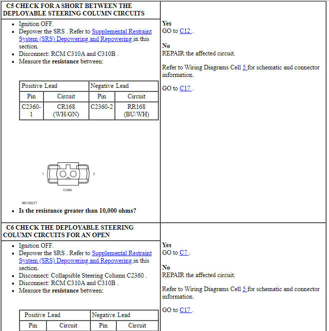
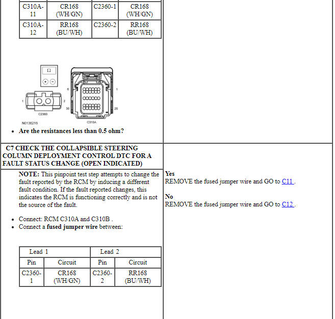
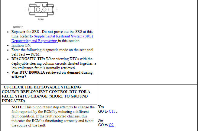
The RCM continuously monitors the deployable steering column and circuits for the following faults:
- Resistance out of range
- Unexpected voltage
- Short to ground
- Faulted deployable steering column
If a fault is detected, the RCM stores DTC B0005:11, B0005:12, B0005:13 or B0005:1A in memory and sends a message to the IPC to illuminate the air bag warning indicator.
The RCM analyzes the deployment loop resistance to determine if a fault exists. The value displayed in the PID is the deployment loop resistance measured by the RCM. If the value displayed is lower or higher than the desired range (refer to diagram below), the RCM can set a DTC. As the deployment loop resistance drifts farther outside the desired range, the chance for a DTC increases. Small variations in resistance can occur due to the effect of road vibrations on terminal fit. Crimps and terminals can be affected by stress and harness movement and can cause an increase in resistance due to wire strain. These variables can result in an intermittent fault. For this reason, the test requires the PID value to be within the desired range before the fault is considered repaired, regardless if the module is reporting an on-demand DTC at the time of diagnosis. Following this direction helps make sure that minor changes in resistance do not create a repeat concern. This test uses process of elimination to diagnose each part of the deployment loop circuit including:
- Wiring
- Connections
- Deployable steering column
- RCM

-
Visual Inspection and Diagnostic Pre-checks
- Inspect for damaged wiring harness(es).
- Inspect for loose or damaged connectors.
-
Possible Sources
- Wiring, terminals or connectors
- Collapsible steering column
- RCM
PINPOINT TEST C: DTCs B0005:11, B0005:12, B0005:13 AND B0005:1A
WARNING: Do not handle, move or change the original horizontal mounting position of the restraints control module (RCM) while the RCM is connected and the ignition switch is ON. Failure to follow this instruction may result in the accidental deployment of the Safety Canopy and cause serious personal injury or death.
WARNING: Never probe the electrical connectors on airbag, Safety Canopy or side air curtain assemblies. Failure to follow this instruction may result in the accidental deployment of these assemblies, which increases the risk of serious personal injury or death.
NOTICE: Use the correct probe adapter(s) from the Flex Probe Kit when taking measurements. Failure to use the correct probe adapter(s) may damage the connector.
NOTE: Most faults are due to connector and/or wiring concerns. Carry out a thorough inspection and verification before proceeding with the pinpoint test.
NOTE: Only disconnect or reconnect SRS components when instructed to do so within a pinpoint test step. Failure to follow this instruction may result in incorrect diagnosis of the SRS.
NOTE: Always make sure the correct SRS component is being installed. Parts released for other vehicles may not be compatible even if they appear physically similar. Check the part number listed in the parts catalog to make sure the correct component is being installed. If an incorrect SRS component is installed, DTCs may set.
NOTE: The SRS must be fully operational and free of faults before releasing the vehicle to the customer.
Pinpoint Test D: DTCs B0010:11, B0010:12, B0010:13 and B0010:1A
Diagnostic Overview
Diagnostics in this manual assume a certain skill level and knowledge of Ford-specific diagnostic practices. Refer to Diagnostic Methods in Section 100-00 for information about these practices.
Refer to Wiring Diagrams Cell 46, Supplemental Restraint System for schematic and connector information.
Normal Operation and Fault Conditions
The RCM continuously monitors the passenger air bag module stage 1 and circuits for the following faults:
- Resistance out of range
- Unexpected voltage
- Short to ground
- Faulted passenger air bag module
If a fault is detected, the RCM stores DTC B0010:11, B0010:12, B0010:13 or B0010:1A in memory and sends a message to the IPC to illuminate the air bag warning indicator.
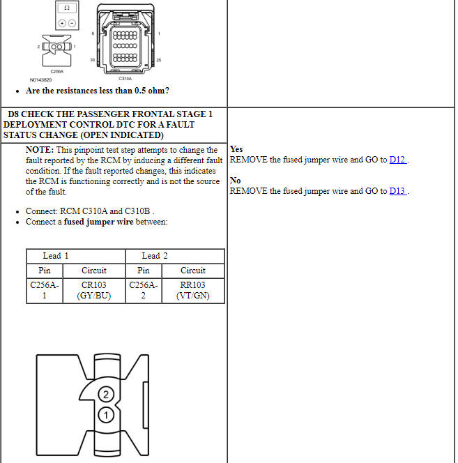
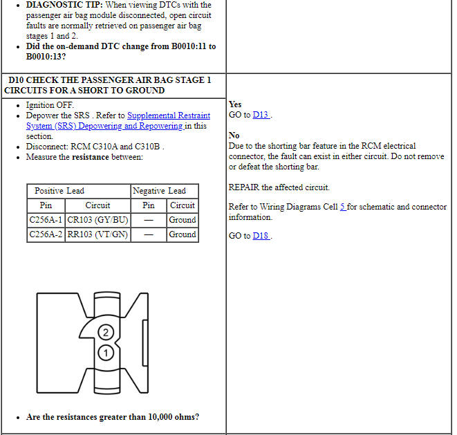
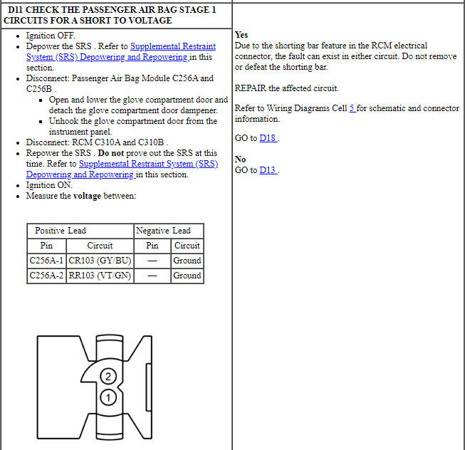
The RCM analyzes the deployment loop resistance to determine if a fault exists. The value displayed in the PID is the deployment loop resistance measured by the RCM. If the value displayed is lower or higher than the desired range (refer to diagram below), the RCM can set a DTC. As the deployment loop resistance drifts farther outside the desired range, the chance for a DTC increases. Small variations in resistance can occur due to the effect of road vibrations on terminal fit. Crimps and terminals can be affected by stress and harness movement and can cause an increase in resistance due to wire strain. These variables can result in an intermittent fault. For this reason, the test requires the PID value to be within the desired range before the fault is considered repaired, regardless if the module is reporting an on-demand DTC at the time of diagnosis. Following this direction helps make sure that minor changes in resistance do not create a repeat concern. This test uses process of elimination to diagnose each part of the deployment loop circuit including:
- Wiring
- Connections
- Passenger air bag module
- RCM

-
Visual Inspection and Diagnostic Pre-checks
- Inspect for damaged wiring harness(es).
- Inspect for loose or damaged connectors.
-
Possible Sources
- Wiring, terminals or connectors
- Passenger air bag module
- RCM
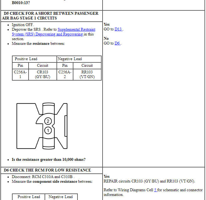
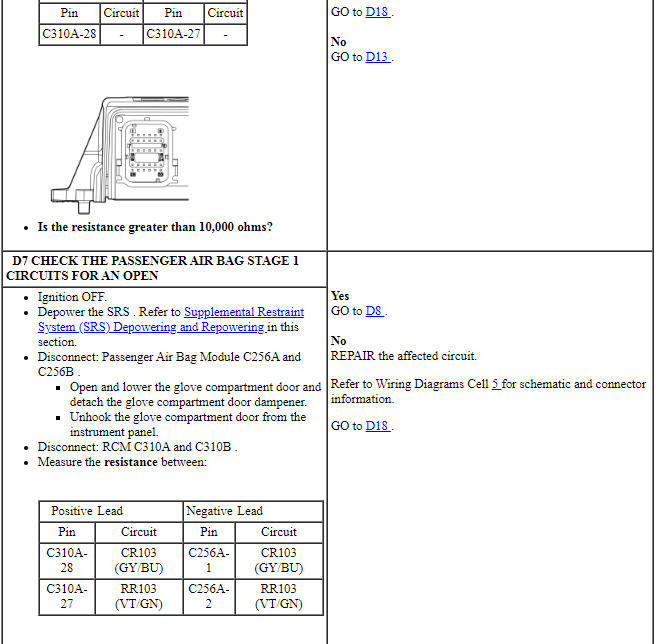
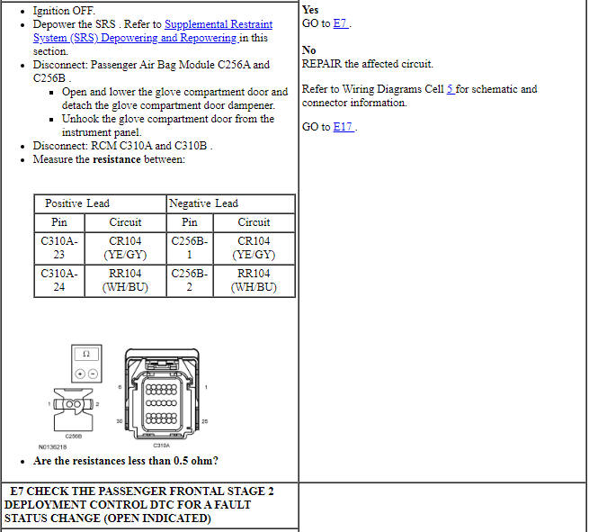
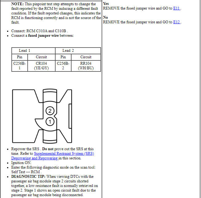
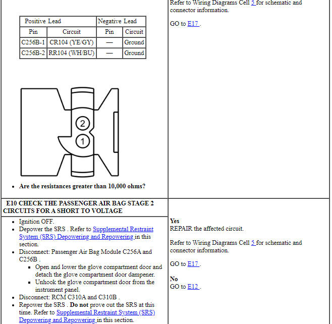
PINPOINT TEST D: DTCs B0010:11, B0010:12, B0010:13 AND B0010:1A
WARNING: Do not handle, move or change the original horizontal mounting position of the restraints control module (RCM) while the RCM is connected and the ignition switch is ON. Failure to follow this instruction may result in the accidental deployment of the Safety Canopy and cause serious personal injury or death.
WARNING: Never probe the electrical connectors on airbag, Safety Canopy or side air curtain assemblies. Failure to follow this instruction may result in the accidental deployment of these assemblies, which increases the risk of serious personal injury or death.
NOTICE: Use the correct probe adapter(s) from the Flex Probe Kit when taking measurements. Failure to use the correct probe adapter(s) may damage the connector.
NOTE: Most faults are due to connector and/or wiring concerns. Carry out a thorough inspection and verification before proceeding with the pinpoint test.
NOTE: Only disconnect or reconnect SRS components when instructed to do so within a pinpoint test step. Failure to follow this instruction may result in incorrect diagnosis of the SRS.
NOTE: Always make sure the correct SRS component is being installed. Parts released for other vehicles may not be compatible even if they appear physically similar. Check the part number listed in the parts catalog to make sure the correct component is being installed. If an incorrect SRS component is installed, DTCs may set.
NOTE: The SRS must be fully operational and free of faults before releasing the vehicle to the customer.
Pinpoint Test E: DTCs B0011:11, B0011:12, B0011:13 and B0011:1A
Diagnostic Overview
Diagnostics in this manual assume a certain skill level and knowledge of Ford-specific diagnostic practices. Refer to Diagnostic Methods in Section 100-00 for information about these practices.
Refer to Wiring Diagrams Cell 46, Supplemental Restraint System for schematic and connector information.
Normal Operation and Fault Conditions
The RCM continuously monitors the passenger air bag module stage 2 and circuits for the following faults:
- Resistance out of range
- Unexpected voltage
- Short to ground
- Faulted passenger air bag module
If a fault is detected, the RCM stores DTC B0011:11, B0011:12, B0011:13 or B0011:1A in memory and sends a message to the IPC to illuminate the air bag warning indicator.
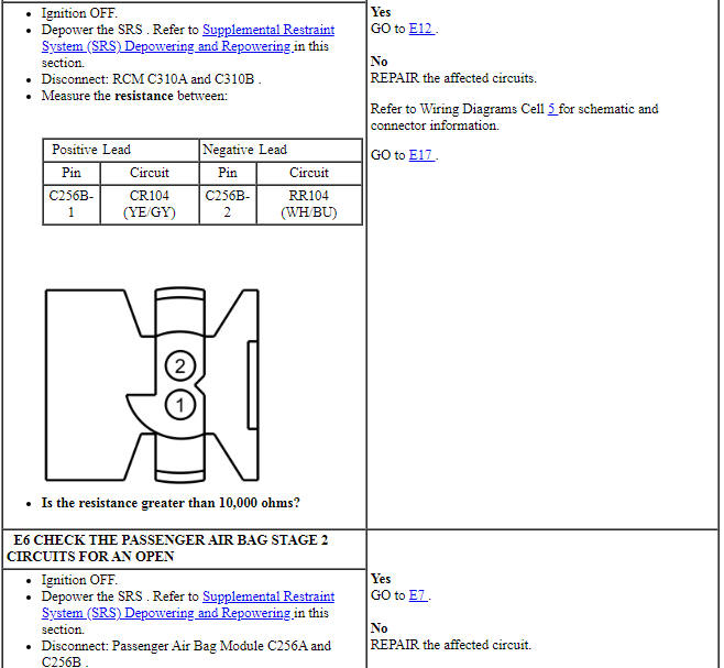
The RCM analyzes the deployment loop resistance to determine if a fault exists. The value displayed in the PID is the deployment loop resistance measured by the RCM. If the value displayed is lower or higher than the desired range (refer to diagram below), the RCM can set a DTC. As the deployment loop resistance drifts farther outside the desired range, the chance for a DTC increases. Small variations in resistance can occur due to the effect of road vibrations on terminal fit. Crimps and terminals can be affected by stress and harness movement and can cause an increase in resistance due to wire strain. These variables can result in an intermittent fault. For this reason, the test requires the PID value to be within the desired range before the fault is considered repaired, regardless if the module is reporting an on-demand DTC at the time of diagnosis. Following this direction helps make sure that minor changes in resistance do not create a repeat concern. This test uses process of elimination to diagnose each part of the deployment loop circuit including:
- Wiring
- Connections
- Passenger air bag module
- RCM

-
Visual Inspection and Diagnostic Pre-checks
- Inspect for damaged wiring harness(es).
- Inspect for loose or damaged connectors.
-
Possible Sources
- Wiring, terminals or connectors
- Passenger air bag module
- RCM
PINPOINT TEST E: DTCs B0011:11, B0011:12, B0011:13 AND B0011:1A
WARNING: Do not handle, move or change the original horizontal mounting position of the restraints control module (RCM) while the RCM is connected and the ignition switch is ON. Failure to follow this instruction may result in the accidental deployment of the Safety Canopy and cause serious personal injury or death.
WARNING: Never probe the electrical connectors on airbag, Safety Canopy or side air curtain assemblies. Failure to follow this instruction may result in the accidental deployment of these assemblies, which increases the risk of serious personal injury or death.
NOTICE: Use the correct probe adapter(s) from the Flex Probe Kit when taking measurements. Failure to use the correct probe adapter(s) may damage the connector.
NOTE: Most faults are due to connector and/or wiring concerns. Carry out a thorough inspection and verification before proceeding with the pinpoint test.
NOTE: Only disconnect or reconnect SRS components when instructed to do so within a pinpoint test step. Failure to follow this instruction may result in incorrect diagnosis of the SRS.
NOTE: Always make sure the correct SRS component is being installed. Parts released for other vehicles may not be compatible even if they appear physically similar. Check the part number listed in the parts catalog to make sure the correct component is being installed. If an incorrect SRS component is installed, DTCs may set.
NOTE: The SRS must be fully operational and free of faults before releasing the vehicle to the customer.
Pinpoint Test F: DTCs B0050:11, B0050:12, B0050:13 and B0050:1D
Diagnostic Overview
Diagnostics in this manual assume a certain skill level and knowledge of Ford-specific diagnostic practices. Refer to Diagnostic Methods in Section 100-00 for information about these practices.
Refer to Wiring Diagrams Cell 46, Supplemental Restraint System for schematic and connector information.
Normal Operation and Fault Conditions
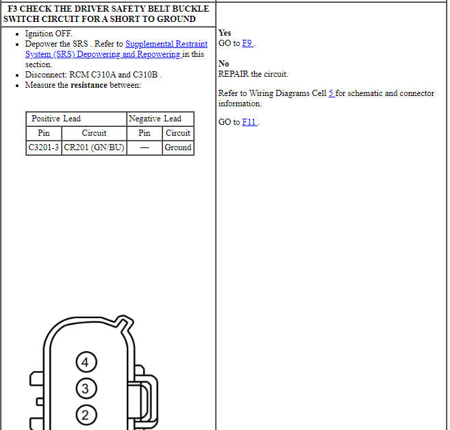
The RCM monitors the driver safety belt buckle switch and circuits for the following faults:
- Open circuit
- Short to voltage
- Short to ground
- Current out of range
- Faulted driver safety belt buckle switch
If a fault is detected, the RCM stores DTC B0050:11, B0050:12, B0050:13 or B0050:1D in memory and sends a message to the IPC to illuminate the air bag warning indicator.
-
Visual Inspection and Diagnostic Pre-checks
- Inspect for a damaged driver safety belt buckle.
- Inspect for damaged wiring harness(es).
- Inspect for loose or damaged connectors.
-
Possible Sources
- Wiring, terminals or connectors
- Driver safety belt buckle
- RCM
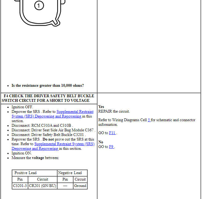
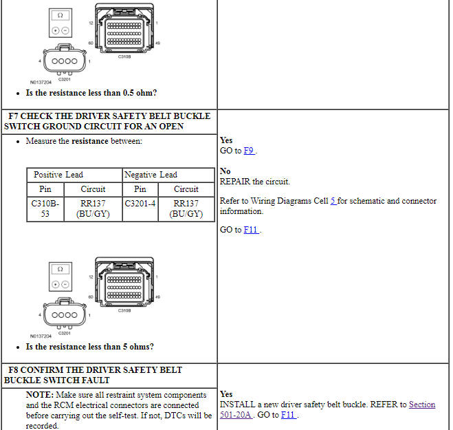
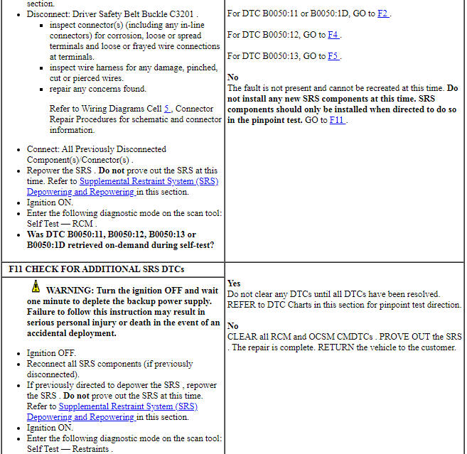
PINPOINT TEST F: DTCs B0050:11, B0050:12, B0050:13 AND B0050:1D
WARNING: Do not handle, move or change the original horizontal mounting position of the restraints control module (RCM) while the RCM is connected and the ignition switch is ON. Failure to follow this instruction may result in the accidental deployment of the Safety Canopy and cause serious personal injury or death.
WARNING: Never probe the electrical connectors on airbag, Safety Canopy or side air curtain assemblies. Failure to follow this instruction may result in the accidental deployment of these assemblies, which increases the risk of serious personal injury or death.
WARNING: Never disassemble or tamper with seat belt deployable components, including pretensioners, load limiters and inflators. Never back probe deployable device electrical connectors. Tampering or back probing may cause an accidental deployment and result in personal injury or death.
NOTICE: Use the correct probe adapter(s) from the Flex Probe Kit when taking measurements. Failure to use the correct probe adapter(s) may damage the connector.
NOTE: Most faults are due to connector and/or wiring concerns. Carry out a thorough inspection and verification before proceeding with the pinpoint test.
NOTE: Only disconnect or reconnect SRS components when instructed to do so within a pinpoint test step. Failure to follow this instruction may result in incorrect diagnosis of the SRS.
NOTE: Always make sure the correct SRS component is being installed. Parts released for other vehicles may not be compatible even if they appear physically similar. Check the part number listed in the parts catalog to make sure the correct component is being installed. If an incorrect SRS component is installed, DTCs may set.
NOTE: The SRS must be fully operational and free of faults before releasing the vehicle to the customer.
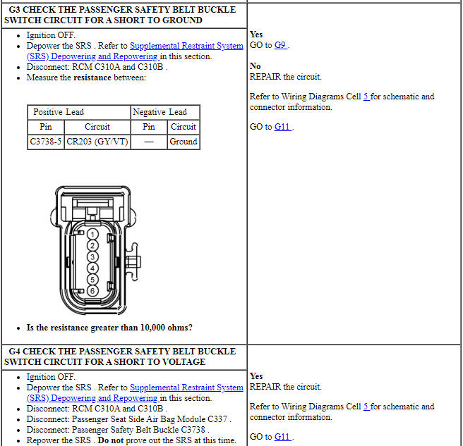
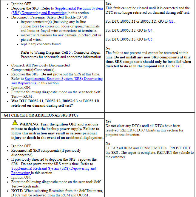
Pinpoint Test G: DTCs B0052:11, B0052:12, B0052:13 and B0052:1D
Diagnostic Overview
Diagnostics in this manual assume a certain skill level and knowledge of Ford-specific diagnostic practices. Refer to Diagnostic Methods in Section 100-00 for information about these practices.
Refer to Wiring Diagrams Cell 46, Supplemental Restraint System for schematic and connector information.
Normal Operation and Fault Conditions
The RCM monitors the passenger safety belt buckle switch and circuits for the following faults:
- Open circuit
- Short to voltage
- Short to ground
- Current out of range
- Faulted passenger safety belt buckle switch
If a fault is detected, the RCM stores DTC B0052:11, B0052:12, B0052:13 or B0052:1D in memory and sends a message to the IPC to illuminate the air bag warning indicator.
-
Visual Inspection and Diagnostic Pre-checks
- Inspect for a damaged passenger safety belt buckle.
- Inspect for damaged wiring harness(es).
- Inspect for loose or damaged connectors.
-
Possible Sources
- Wiring, terminals or connectors
- Passenger safety belt buckle
- RCM
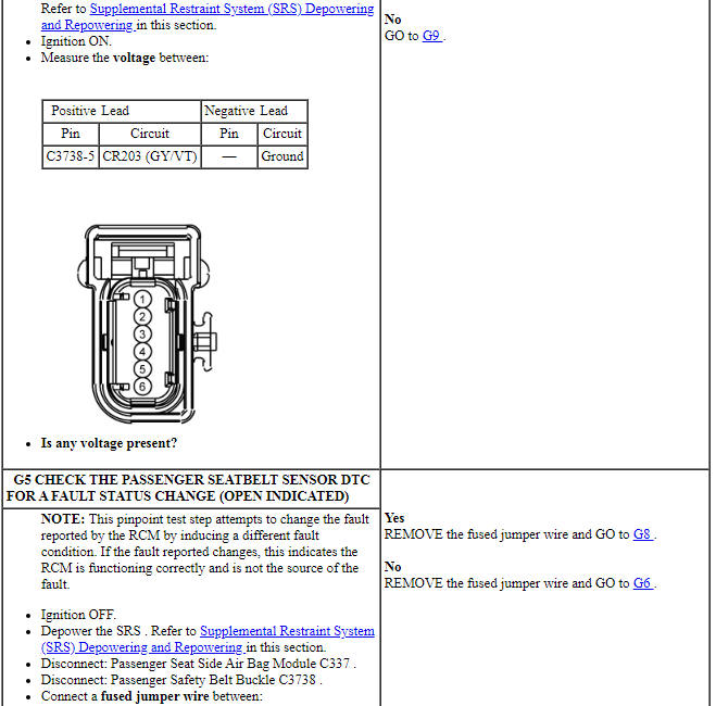
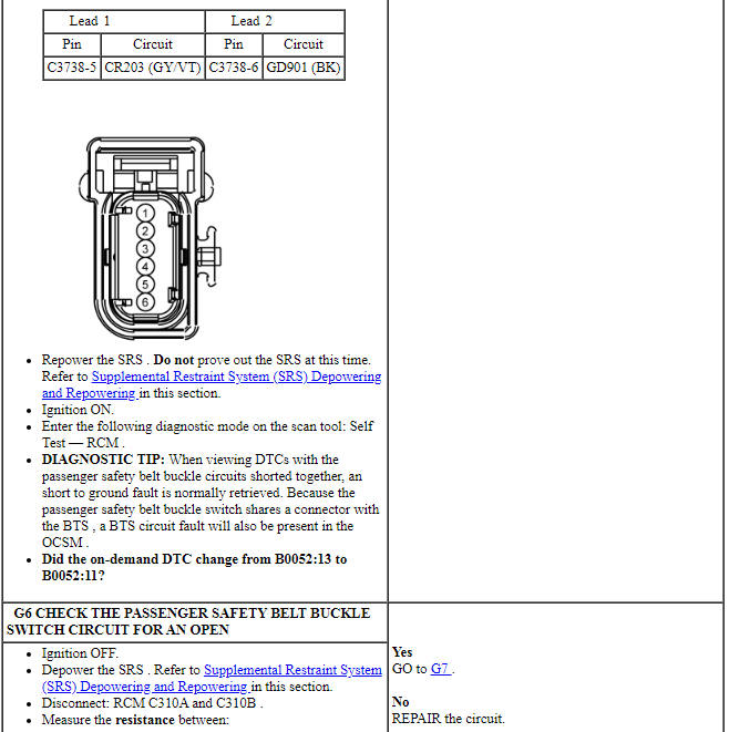
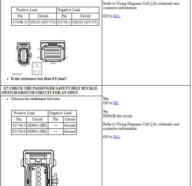
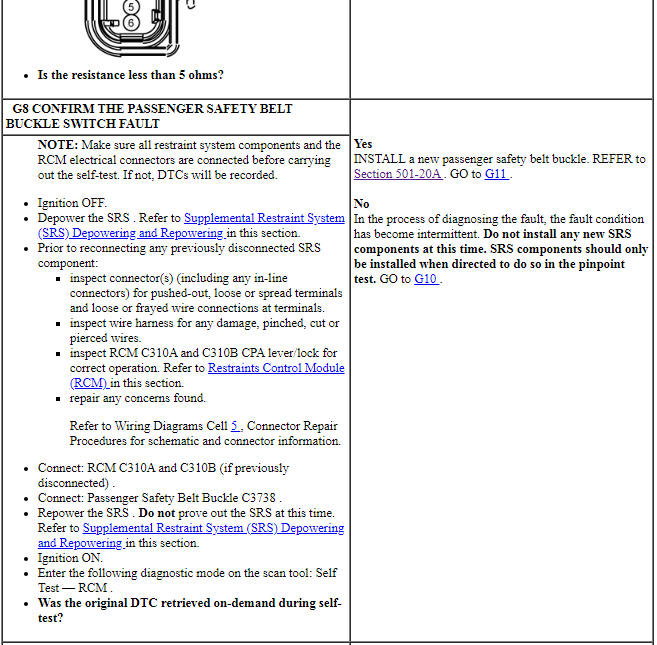
PINPOINT TEST G: DTCs B0052:11, B0052:12, B0052:13 AND B0052:1D
WARNING: Do not handle, move or change the original horizontal mounting position of the restraints control module (RCM) while the RCM is connected and the ignition switch is ON. Failure to follow this instruction may result in the accidental deployment of the Safety Canopy and cause serious personal injury or death.
WARNING: Never disassemble or tamper with seat belt deployable components, including pretensioners, load limiters and inflators. Never back probe deployable device electrical connectors. Tampering or back probing may cause an accidental deployment and result in personal injury or death.
WARNING: Never probe the electrical connectors on airbag, Safety Canopy or side air curtain assemblies. Failure to follow this instruction may result in the accidental deployment of these assemblies, which increases the risk of serious personal injury or death.
NOTICE: Use the correct probe adapter(s) from the Flex Probe Kit when taking measurements. Failure to use the correct probe adapter(s) may damage the connector.
NOTE: Most faults are due to connector and/or wiring concerns. Carry out a thorough inspection and verification before proceeding with the pinpoint test.
NOTE: Only disconnect or reconnect SRS components when instructed to do so within a pinpoint test step. Failure to follow this instruction may result in incorrect diagnosis of the SRS.
NOTE: Always make sure the correct SRS component is being installed. Parts released for other vehicles may not be compatible even if they appear physically similar. Check the part number listed in the parts catalog to make sure the correct component is being installed. If an incorrect SRS component is installed, DTCs may set.
NOTE: The SRS must be fully operational and free of faults before releasing the vehicle to the customer.

Pinpoint Test H: DTCs B0070:11, B0070:12, B0070:13 and B0070:1A
Diagnostic Overview
Diagnostics in this manual assume a certain skill level and knowledge of Ford-specific diagnostic practices. Refer to Diagnostic Methods in Section 100-00 for information about these practices.
Refer to Wiring Diagrams Cell 46, Supplemental Restraint System for schematic and connector information.
Normal Operation and Fault Conditions
The RCM monitors the driver safety belt anchor pretensioner and circuits for the following faults:
- Resistance out of range
- Unexpected voltage
- Short to ground
- Faulted driver safety belt anchor pretensioner
If a fault is detected, the RCM stores DTC B0070:11, B0070:12, B0070:13 or B0070:1A in memory and sends a message to the IPC module to illuminate the air bag warning indicator.
The RCM analyzes the deployment loop resistance to determine if a fault exists. The value displayed in the PID is the deployment loop resistance measured by the RCM. If the value displayed is lower or higher than the desired range (refer to diagram below), the RCM can set a DTC. As the deployment loop resistance drifts farther outside the desired range, the chance for a DTC increases. Small variations in resistance can occur due to the effect of road vibrations on terminal fit. Crimps and terminals can be affected by stress and harness movement and can cause an increase in resistance due to wire strain. These variables can result in an intermittent fault. For this reason, the test requires the PID value to be within the desired range before the fault is considered repaired, regardless if the module is reporting an on-demand DTC at the time of diagnosis. Following this direction helps make sure that minor changes in resistance do not create a repeat concern. This test uses process of elimination to diagnose each part of the deployment loop circuit including:
- Wiring
- Connections
- Driver safety belt anchor pretensioner
- RCM

-
Visual Inspection and Diagnostic Pre-checks
- Inspect for damaged wiring harness(es).
- Inspect for loose or damaged connectors.
-
Possible Sources
- Wiring, terminals or connectors
- Driver safety belt anchor pretensioner
- RCM
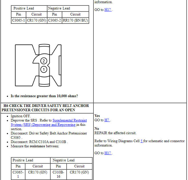
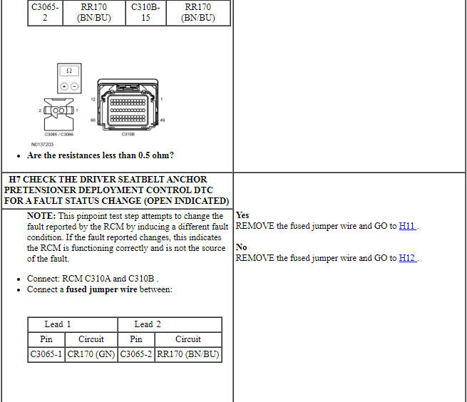
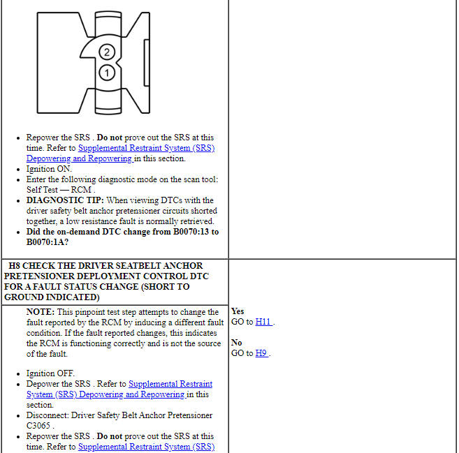
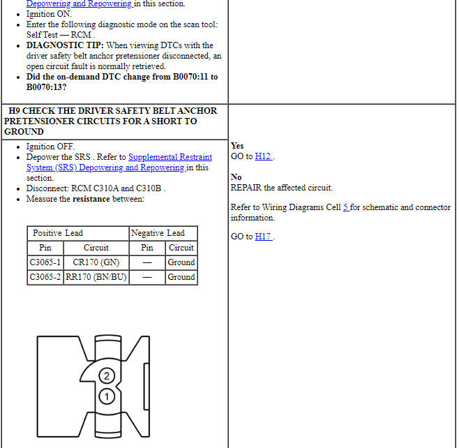
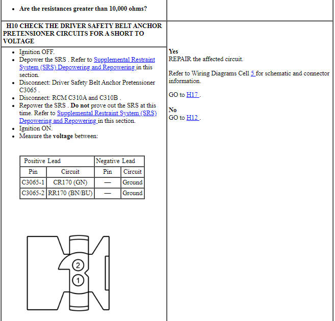
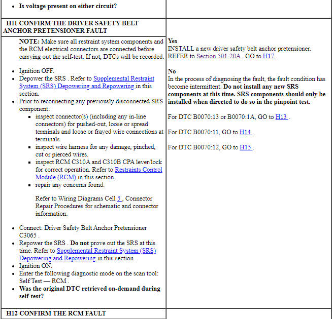
PINPOINT TEST H: DTCs B0070:11, B0070:12, B0070:13 AND B0070:1A
WARNING: Do not handle, move or change the original horizontal mounting position of the restraints control module (RCM) while the RCM is connected and the ignition switch is ON. Failure to follow this instruction may result in the accidental deployment of the Safety Canopy and cause serious personal injury or death.
WARNING: Never probe the electrical connectors on airbag, Safety Canopy or side air curtain assemblies. Failure to follow this instruction may result in the accidental deployment of these assemblies, which increases the risk of serious personal injury or death.
WARNING: Never disassemble or tamper with seat belt deployable components, including pretensioners, load limiters and inflators. Never back probe deployable device electrical connectors. Tampering or back probing may cause an accidental deployment and result in personal injury or death.
NOTICE: Use the correct probe adapter(s) from the Flex Probe Kit when taking measurements. Failure to use the correct probe adapter(s) may damage the connector.
NOTE: Most faults are due to connector and/or wiring concerns. Carry out a thorough inspection and verification before proceeding with the pinpoint test.
NOTE: Only disconnect or reconnect SRS components when instructed to do so within a pinpoint test step. Failure to follow this instruction may result in incorrect diagnosis of the SRS.
NOTE: Always make sure the correct SRS component is being installed. Parts released for other vehicles may not be compatible even if they appear physically similar. Check the part number listed in the parts catalog to make sure the correct component is being installed. If an incorrect SRS component is installed, DTCs may set.
NOTE: The SRS must be fully operational and free of faults before releasing the vehicle to the customer.
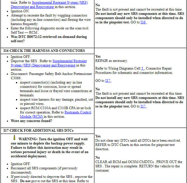
Pinpoint Test I: DTCs B0072:11, B0072:12, B0072:13 and B0072:1A
Diagnostic Overview
Diagnostics in this manual assume a certain skill level and knowledge of Ford-specific diagnostic practices. Refer to Diagnostic Methods in Section 100-00 for information about these practices.
Refer to Wiring Diagrams Cell 46, Supplemental Restraint System for schematic and connector information.
Normal Operation and Fault Conditions
The RCM monitors the passenger safety belt anchor pretensioner and circuits for the following faults:
- Resistance out of range
- Unexpected voltage
- Short to ground
- Faulted passenger safety belt anchor pretensioner
If a fault is detected, the RCM stores DTC B0072:11, B0072:12, B0072:13 or B0072:1A in memory and sends a message to the IPC module to illuminate the air bag warning indicator.
The RCM analyzes the deployment loop resistance to determine if a fault exists. The value displayed in the PID is the deployment loop resistance measured by the RCM. If the value displayed is lower or higher than the desired range (refer to diagram below), the RCM can set a DTC. As the deployment loop resistance drifts farther outside the desired range, the chance for a DTC increases. Small variations in resistance can occur due to the effect of road vibrations on terminal fit. Crimps and terminals can be affected by stress and harness movement and can cause an increase in resistance due to wire strain. These variables can result in an intermittent fault. For this reason, the test requires the PID value to be within the desired range before the fault is considered repaired, regardless if the module is reporting an on-demand DTC at the time of diagnosis. Following this direction helps make sure that minor changes in resistance do not create a repeat concern. This test uses process of elimination to diagnose each part of the deployment loop circuit including:
- Wiring
- Connections
- Passenger safety belt anchor pretensioner
- RCM

-
Visual Inspection and Diagnostic Pre-checks
- Inspect for damaged wiring harness(es).
- Inspect for loose or damaged connectors.
-
Possible Sources
- Wiring, terminals or connectors
- Passenger safety belt anchor pretensioner
- RCM
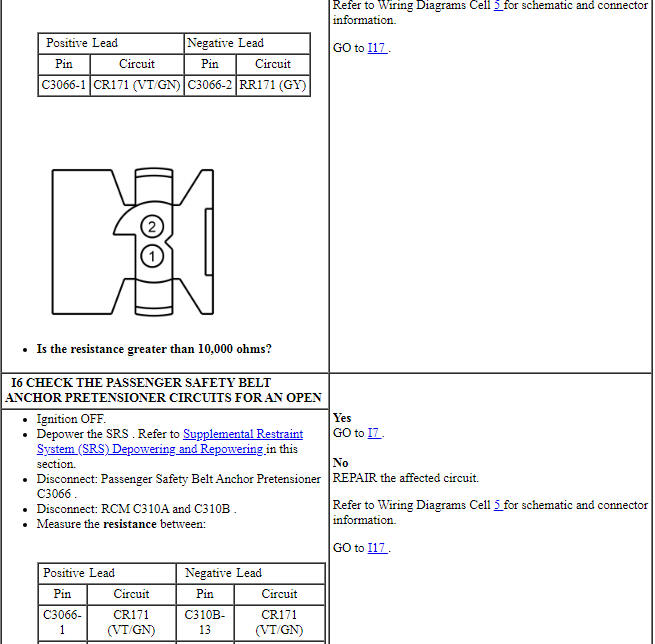
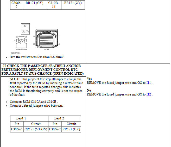
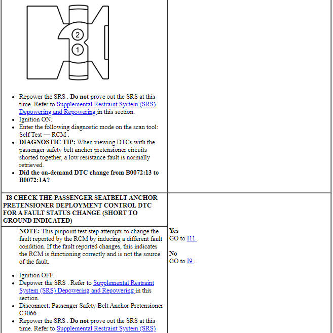
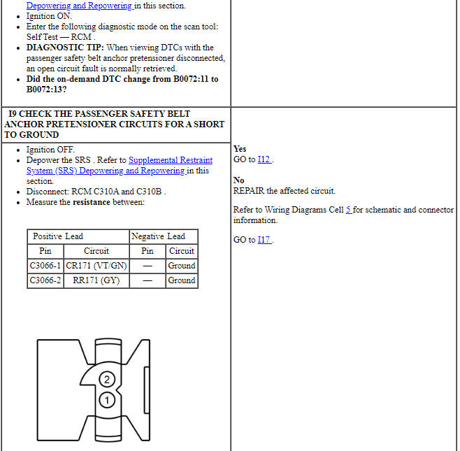
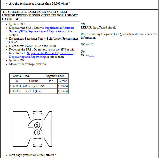
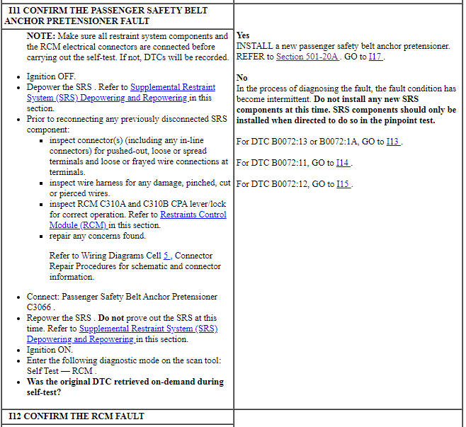
PINPOINT TEST I: DTCs B0072:11, B0072:12, B0072:13 AND B0072:1A
WARNING: Do not handle, move or change the original horizontal mounting position of the restraints control module (RCM) while the RCM is connected and the ignition switch is ON. Failure to follow this instruction may result in the accidental deployment of the Safety Canopy and cause serious personal injury or death.
WARNING: Never probe the electrical connectors on airbag, Safety Canopy or side air curtain assemblies. Failure to follow this instruction may result in the accidental deployment of these assemblies, which increases the risk of serious personal injury or death.
WARNING: Never disassemble or tamper with seat belt deployable components, including pretensioners, load limiters and inflators. Never back probe deployable device electrical connectors. Tampering or back probing may cause an accidental deployment and result in personal injury or death.
NOTICE: Use the correct probe adapter(s) from the Flex Probe Kit when taking measurements. Failure to use the correct probe adapter(s) may damage the connector.
NOTE: Most faults are due to connector and/or wiring concerns. Carry out a thorough inspection and verification before proceeding with the pinpoint test.
NOTE: Only disconnect or reconnect SRS components when instructed to do so within a pinpoint test step. Failure to follow this instruction may result in incorrect diagnosis of the SRS.
NOTE: Always make sure the correct SRS component is being installed. Parts released for other vehicles may not be compatible even if they appear physically similar. Check the part number listed in the parts catalog to make sure the correct component is being installed. If an incorrect SRS component is installed, DTCs may set.
NOTE: The SRS must be fully operational and free of faults before releasing the vehicle to the customer.
Pinpoint Test J: DTCs B007E:11, B007E:12, B007E:13 and B007E:1A
Diagnostic Overview
Diagnostics in this manual assume a certain skill level and knowledge of Ford-specific diagnostic practices. Refer to Diagnostic Methods in Section 100-00 for information about these practices.
Refer to Wiring Diagrams Cell 46, Supplemental Restraint System for schematic and connector information.
Normal Operation and Fault Conditions
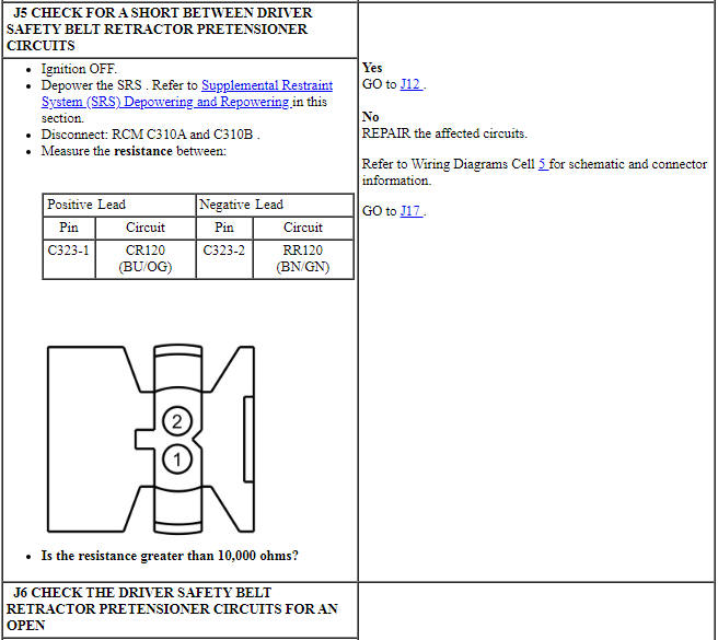
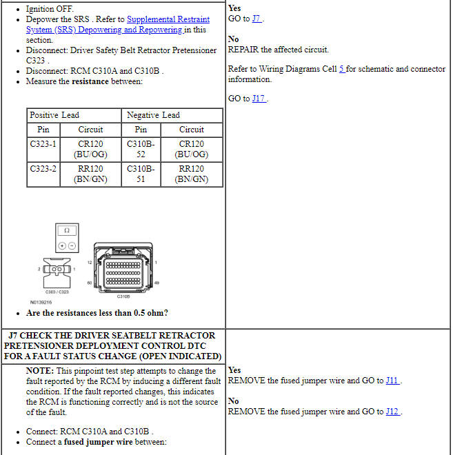
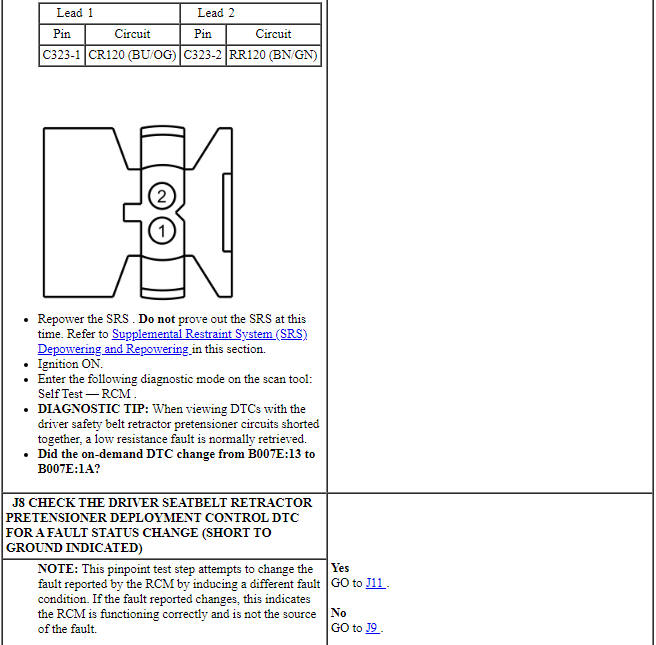
The RCM monitors the driver safety belt retractor pretensioner and circuits for the following faults:
- Resistance out of range
- Unexpected voltage
- Short to ground
- Faulted driver safety belt retractor pretensioner
If a fault is detected, the RCM stores DTC B007E:11, B007E:12, B007E:13 or B007E:1A in memory and sends a message to the IPC module to illuminate the air bag warning indicator.
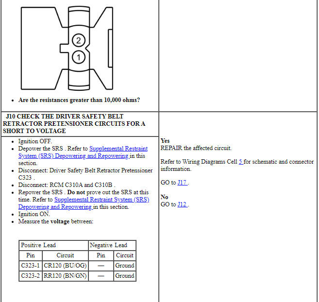
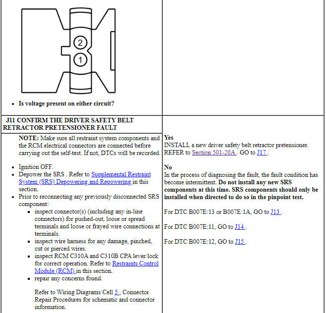
The RCM analyzes the deployment loop resistance to determine if a fault exists. The value displayed in the PID is the deployment loop resistance measured by the RCM. If the value displayed is lower or higher than the desired range (refer to diagram below), the RCM can set a DTC. As the deployment loop resistance drifts farther outside the desired range, the chance for a DTC increases. Small variations in resistance can occur due to the effect of road vibrations on terminal fit. Crimps and terminals can be affected by stress and harness movement and can cause an increase in resistance due to wire strain. These variables can result in an intermittent fault. For this reason, the test requires the PID value to be within the desired range before the fault is considered repaired, regardless if the module is reporting an on-demand DTC at the time of diagnosis. Following this direction helps make sure that minor changes in resistance do not create a repeat concern. This test uses process of elimination to diagnose each part of the deployment loop circuit including:
- Wiring
- Connections
- Driver safety belt retractor pretensioner
- RCM
-
Visual Inspection and Diagnostic Pre-checks
- Inspect for damaged wiring harness(es).
- Inspect for loose or damaged connectors.
-
Possible Sources
- Wiring, terminals or connectors
- Driver safety belt retractor pretensioner
- RCM
PINPOINT TEST J: DTCs B007E:11, B007E:12, B007E:13 AND B007E:1A
WARNING: Do not handle, move or change the original horizontal mounting position of the restraints control module (RCM) while the RCM is connected and the ignition switch is ON. Failure to follow this instruction may result in the accidental deployment of the Safety Canopy and cause serious personal injury or death.
WARNING: Never probe the electrical connectors on airbag, Safety Canopy or side air curtain assemblies. Failure to follow this instruction may result in the accidental deployment of these assemblies, which increases the risk of serious personal injury or death.
WARNING: Never disassemble or tamper with seat belt deployable components, including pretensioners, load limiters and inflators. Never back probe deployable device electrical connectors. Tampering or back probing may cause an accidental deployment and result in personal injury or death.
NOTICE: Use the correct probe adapter(s) from the Flex Probe Kit when taking measurements. Failure to use the correct probe adapter(s) may damage the connector.
NOTE: Most faults are due to connector and/or wiring concerns. Carry out a thorough inspection and verification before proceeding with the pinpoint test.
NOTE: Only disconnect or reconnect SRS components when instructed to do so within a pinpoint test step. Failure to follow this instruction may result in incorrect diagnosis of the SRS.
NOTE: Always make sure the correct SRS component is being installed. Parts released for other vehicles may not be compatible even if they appear physically similar. Check the part number listed in the parts catalog to make sure the correct component is being installed. If an incorrect SRS component is installed, DTCs may set.
NOTE: The SRS must be fully operational and free of faults before releasing the vehicle to the customer.
Pinpoint Test K: DTCs B007F:11, B007F:12, B007F:13 and B007F:1A
Diagnostic Overview
Diagnostics in this manual assume a certain skill level and knowledge of Ford-specific diagnostic practices. Refer to Diagnostic Methods in Section 100-00 for information about these practices.
Refer to Wiring Diagrams Cell 46, Supplemental Restraint System for schematic and connector information.
Normal Operation and Fault Conditions
The RCM monitors the passenger safety belt retractor pretensioner and circuits for the following faults:
- Resistance out of range
- Unexpected voltage
- Short to ground
- Faulted passenger safety belt retractor pretensioner
If a fault is detected, the RCM stores DTC B007F:11, B007F:12, B007F:13 or B007F:1A in memory and sends a message to the IPC module to illuminate the air bag warning indicator.
The RCM analyzes the deployment loop resistance to determine if a fault exists. The value displayed in the PID is the deployment loop resistance measured by the RCM. If the value displayed is lower or higher than the desired range (refer to diagram below), the RCM can set a DTC. As the deployment loop resistance drifts farther outside the desired range, the chance for a DTC increases. Small variations in resistance can occur due to the effect of road vibrations on terminal fit. Crimps and terminals can be affected by stress and harness movement and can cause an increase in resistance due to wire strain. These variables can result in an intermittent fault. For this reason, the test requires the PID value to be within the desired range before the fault is considered repaired, regardless if the module is reporting an on-demand DTC at the time of diagnosis. Following this direction helps make sure that minor changes in resistance do not create a repeat concern. This test uses process of elimination to diagnose each part of the deployment loop circuit including:
- Wiring
- Connections
- Passenger safety belt retractor pretensioner
- RCM

-
Visual Inspection and Diagnostic Pre-checks
- Inspect for damaged wiring harness(es).
- Inspect for loose or damaged connectors.
-
Possible Sources
- Wiring, terminals or connectors
- Passenger safety belt retractor pretensioner
- RCM
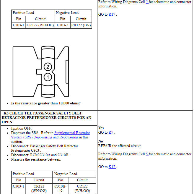
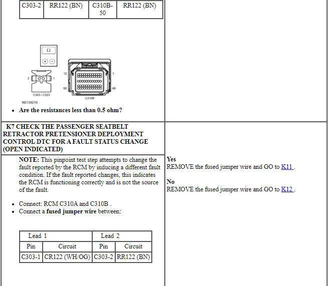
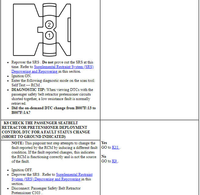
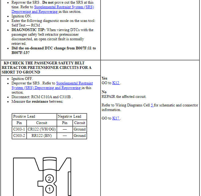
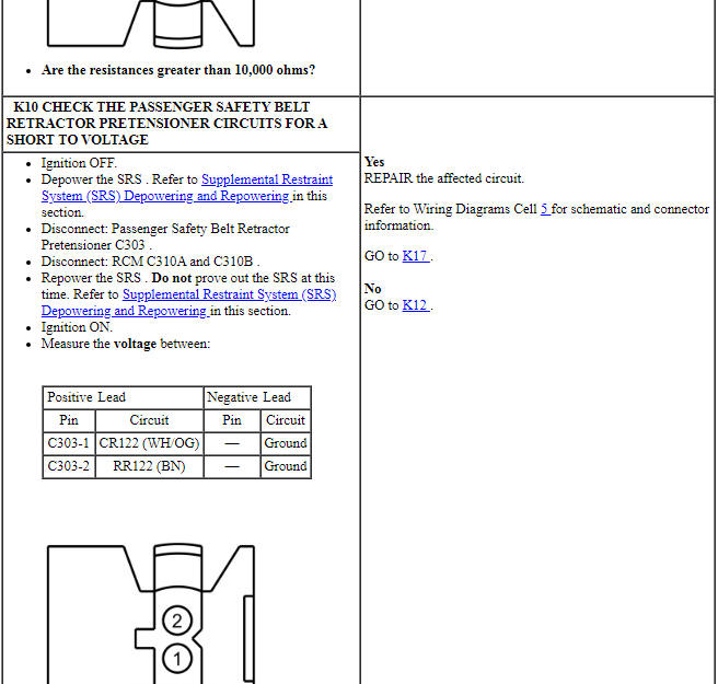
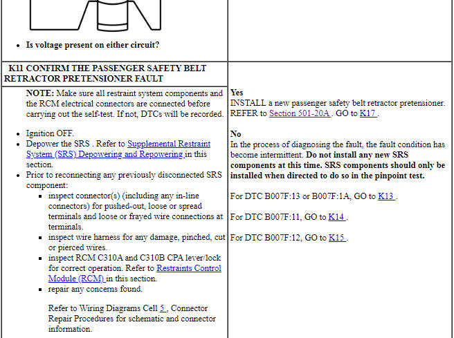
PINPOINT TEST K: DTCs B007F:11, B007F:12, B007F:13 and B007F:1A
WARNING: Do not handle, move or change the original horizontal mounting position of the restraints control module (RCM) while the RCM is connected and the ignition switch is ON. Failure to follow this instruction may result in the accidental deployment of the Safety Canopy and cause serious personal injury or death.
WARNING: Never probe the electrical connectors on airbag, Safety Canopy or side air curtain assemblies. Failure to follow this instruction may result in the accidental deployment of these assemblies, which increases the risk of serious personal injury or death.
WARNING: Never disassemble or tamper with seat belt deployable components, including pretensioners, load limiters and inflators. Never back probe deployable device electrical connectors. Tampering or back probing may cause an accidental deployment and result in personal injury or death.
NOTICE: Use the correct probe adapter(s) from the Flex Probe Kit when taking measurements. Failure to use the correct probe adapter(s) may damage the connector.
NOTE: Most faults are due to connector and/or wiring concerns. Carry out a thorough inspection and verification before proceeding with the pinpoint test.
NOTE: SRS components should only be disconnected or reconnected when instructed to do so within a pinpoint test step. Failure to follow this instruction may result in incorrect diagnosis of the SRS.
NOTE: Always make sure the correct SRS component is being installed. Parts released for other vehicles may not be compatible even if they appear physically similar. Check the part number listed in the parts catalog to make sure the correct component is being installed. If an incorrect SRS component is installed, DTCs may set.
NOTE: The SRS must be fully operational and free of faults before releasing the vehicle to the customer.
Pinpoint Test L: DTCs B0082:11, B0082:12, B0082:13 and B0082:1A
Diagnostic Overview
Diagnostics in this manual assume a certain skill level and knowledge of Ford-specific diagnostic practices. Refer to Diagnostic Methods in Section 100-00 for information about these practices.
Refer to Wiring Diagrams Cell 46, Supplemental Restraint System for schematic and connector information.
Normal Operation and Fault Conditions
The RCM continuously monitors the passenger safety belt retractor and circuits for the following faults:
- Resistance out of range
- Unexpected voltage
- Short to ground
- Faulted passenger safety belt retractor
If a fault is detected, the RCM stores DTC B0082:11, B0082:12, B0082:13 or B0082:1A in memory and sends a message to the IPC module to illuminate the air bag warning indicator.
The RCM analyzes the deployment loop resistance to determine if a fault exists. The value displayed in the PID is the deployment loop resistance measured by the RCM. If the value displayed is lower or higher than the desired range (refer to diagram below), the RCM can set a DTC. As the deployment loop resistance drifts farther outside the desired range, the chance for a DTC increases. Small variations in resistance can occur due to the effect of road vibrations on terminal fit. Crimps and terminals can be affected by stress and harness movement and can cause an increase in resistance due to wire strain. These variables can result in an intermittent fault. For this reason, the test requires the PID value to be within the desired range before the fault is considered repaired, regardless if the module is reporting an on-demand DTC at the time of diagnosis. Following this direction helps make sure that minor changes in resistance do not create a repeat concern. This test uses process of elimination to diagnose each part of the deployment loop circuit including:
- Wiring
- Connections
- Passenger safety belt retractor
- RCM

-
Visual Inspection and Diagnostic Pre-checks
- Inspect for damaged wiring harness(es).
- Inspect for loose or damaged connectors.
-
Possible Sources
- Wiring, terminals or connectors
- Passenger safety belt retractor (includes load limiter)
- RCM
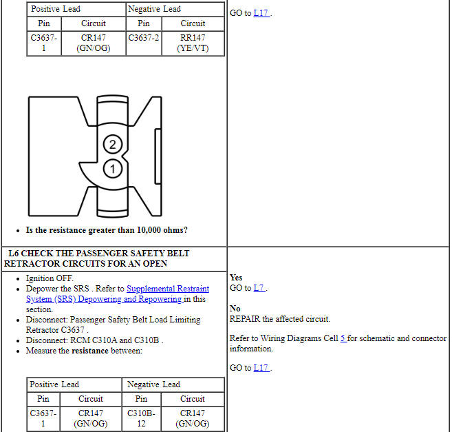
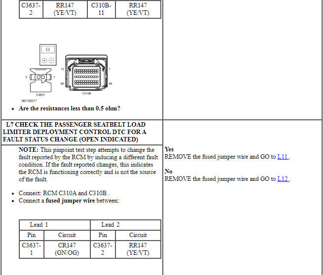
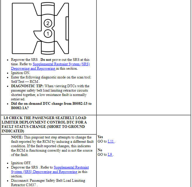
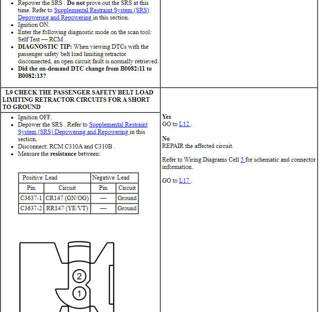
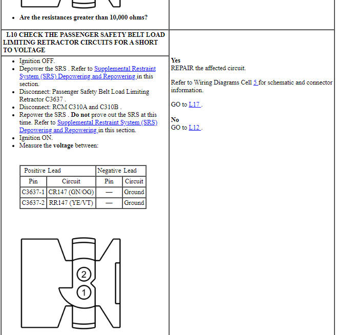
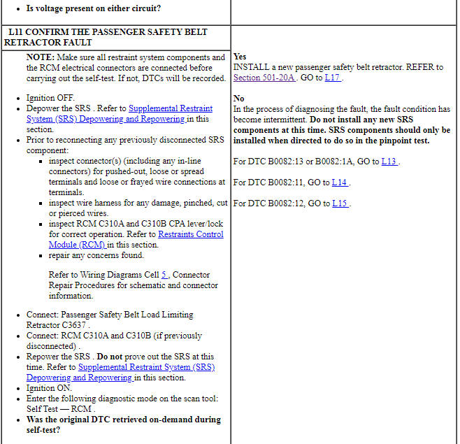
PINPOINT TEST L: DTCs B0082:11, B0082:12, B0082:13 AND B0082:1A
WARNING: Do not handle, move or change the original horizontal mounting position of the restraints control module (RCM) while the RCM is connected and the ignition switch is ON. Failure to follow this instruction may result in the accidental deployment of the Safety Canopy and cause serious personal injury or death.
WARNING: Never disassemble or tamper with seat belt deployable components, including pretensioners, load limiters and inflators. Never back probe deployable device electrical connectors. Tampering or back probing may cause an accidental deployment and result in personal injury or death.
NOTICE: Use the correct probe adapter(s) from the Flex Probe Kit when taking measurements. Failure to use the correct probe adapter(s) may damage the connector.
NOTE: Most faults are due to connector and/or wiring concerns. Carry out a thorough inspection and verification before proceeding with the pinpoint test.
NOTE: Only disconnect or reconnect SRS components when instructed to do so within a pinpoint test step. Failure to follow this instruction may result in incorrect diagnosis of the SRS.
NOTE: Always make sure the correct SRS component is being installed. Parts released for other vehicles may not be compatible even if they appear physically similar. Check the part number listed in the parts catalog to make sure the correct component is being installed. If an incorrect SRS component is installed, DTCs may set.
NOTE: The SRS must be fully operational and free of faults before releasing the vehicle to the customer.
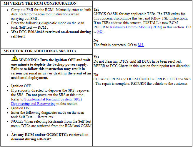
Pinpoint Test M: DTCs B00A0:09, B00A0:4A, B00A0:63, B00A0:64 and B00A0:68
Diagnostic Overview
Diagnostics in this manual assume a certain skill level and knowledge of Ford-specific diagnostic practices. Refer to Diagnostic Methods in Section 100-00 for information about these practices.
Refer to Wiring Diagrams Cell 46, Supplemental Restraint System for schematic and connector information.
Normal Operation and Fault Conditions
The RCM is in constant communication with various control modules on the HS-CAN, one of which is the OCSM. The RCM continuously monitors the HS-CAN for fault messages reported by the OCSM. The RCM also checks for the correct identification of the OCSM. If the RCM receives fault message(s) from the OCSM, it stores DTC B00A0:09, B00A0:4A, B00A0:63, B00A0:64 or B00A0:68 in memory and sends a message to the IPC module to illuminate the air bag warning indicator.

-
Possible Sources
- OCSM
- OCSM DTCs
- RCM
PINPOINT TEST M: DTCs B00A0:09, B00A0:4A, B00A0:63, B00A0:64 AND B00A0:68
WARNING: Do not handle, move or change the original horizontal mounting position of the restraints control module (RCM) while the RCM is connected and the ignition switch is ON. Failure to follow this instruction may result in the accidental deployment of the Safety Canopy and cause serious personal injury or death.
WARNING: Never disassemble or tamper with seat belt deployable components, including pretensioners, load limiters and inflators. Never back probe deployable device electrical connectors. Tampering or back probing may cause an accidental deployment and result in personal injury or death.
WARNING: Never probe the electrical connectors on airbag, Safety Canopy or side air curtain assemblies. Failure to follow this instruction may result in the accidental deployment of these assemblies, which increases the risk of serious personal injury or death.
NOTICE: Use the correct probe adapter(s) from the Flex Probe Kit when taking measurements. Failure to use the correct probe adapter(s) may damage the connector.
NOTE: Most faults are due to connector and/or wiring concerns. Carry out a thorough inspection and verification before proceeding with the pinpoint test.
NOTE: Only disconnect or reconnect SRS components when instructed to do so within a pinpoint test step. Failure to follow this instruction may result in incorrect diagnosis of the SRS.
NOTE: Always make sure the correct SRS component is being installed. Parts released for other vehicles may not be compatible even if they appear physically similar. Check the part number listed in the parts catalog to make sure the correct component is being installed. If an incorrect SRS component is installed, DTCs may set.
NOTE: The SRS must be fully operational and free of faults before releasing the vehicle to the customer.
Pinpoint Test N: DTCs B00B5:11, B00B5:12, B00B5:13 and B00B5:1D
Diagnostic Overview
Diagnostics in this manual assume a certain skill level and knowledge of Ford-specific diagnostic practices. Refer to Diagnostic Methods in Section 100-00 for information about these practices.
Refer to Wiring Diagrams Cell 46, Supplemental Restraint System for schematic and connector information.
Normal Operation and Fault Conditions
The RCM monitors the driver seat track position sensor and circuits for the following faults:
- Short to ground
- Short to voltage
- Open circuit
- Current out of range
- Faulted driver seat track position sensor
If a fault is detected, the RCM stores DTC B00B5:11, B00B5:12, B00B5:13 or B00B5:1D in memory and sends a message to the IPC module to illuminate the air bag warning indicator.
-
Visual Inspection and Diagnostic Pre-checks
- Inspect for a damaged driver seat track position sensor.
- Inspect for damaged wiring harness(es).
- Inspect for loose or damaged connectors.
-
Possible Sources
- Wiring, terminals or connectors
- Driver seat track position sensor
- RCM
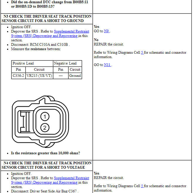
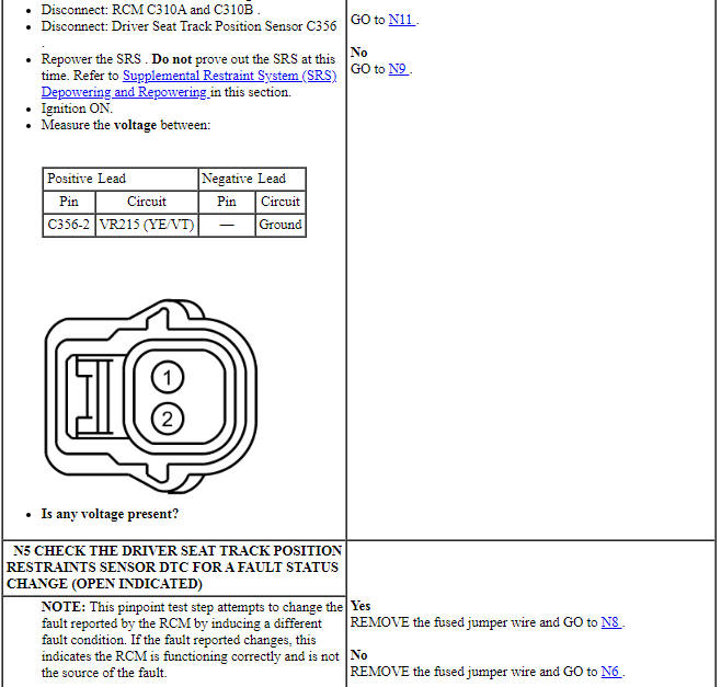
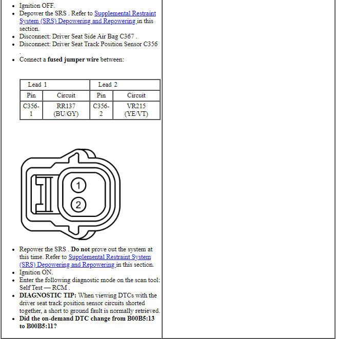
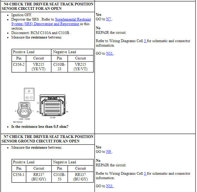
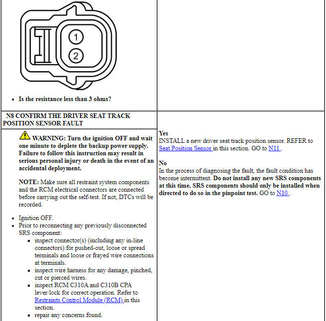
PINPOINT TEST N: DTCs B00B5:11, B00B5:12, B00B5:13 AND B00B5:1D
WARNING: Do not handle, move or change the original horizontal mounting position of the restraints control module (RCM) while the RCM is connected and the ignition switch is ON. Failure to follow this instruction may result in the accidental deployment of the Safety Canopy and cause serious personal injury or death.
WARNING: Never disassemble or tamper with seat belt deployable components, including pretensioners, load limiters and inflators. Never back probe deployable device electrical connectors. Tampering or back probing may cause an accidental deployment and result in personal injury or death.
WARNING: Never probe the electrical connectors on airbag, Safety Canopy or side air curtain assemblies. Failure to follow this instruction may result in the accidental deployment of these assemblies, which increases the risk of serious personal injury or death.
NOTICE: Use the correct probe adapter(s) from the Flex Probe Kit when taking measurements. Failure to use the correct probe adapter(s) may damage the connector.
NOTE: Most faults are due to connector and/or wiring concerns. Carry out a thorough inspection and verification before proceeding with the pinpoint test.
NOTE: Only disconnect or reconnect SRS components when instructed to do so within a pinpoint test step. Failure to follow this instruction may result in incorrect diagnosis of the SRS.
NOTE: Always make sure the correct SRS component is being installed. Parts released for other vehicles may not be compatible even if they appear physically similar. Check the part number listed in the parts catalog to make sure the correct component is being installed. If an incorrect SRS component is installed, DTCs may set.
NOTE: The SRS must be fully operational and free of faults before releasing the vehicle to the customer.
Pinpoint Test O: DTCs B00C5:11, B00C5:12, B00C5:13 and B00C5:1D
Diagnostic Overview
Diagnostics in this manual assume a certain skill level and knowledge of Ford-specific diagnostic practices. Refer to Diagnostic Methods in Section 100-00 for information about these practices.
Refer to Wiring Diagrams Cell 46, Supplemental Restraint System for schematic and connector information.
Normal Operation and Fault Conditions
The RCM monitors the passenger seat track position sensor and circuits for the following faults:
- Short to ground
- Short to voltage
- Open circuit
- Current out of range
- Faulted passenger seat track position sensor
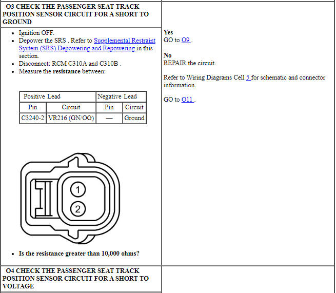
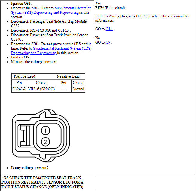
If a fault is detected, the RCM stores DTC B00C5:11, B00C5:12, B00C5:13 or B00C5:1D in memory and sends a message to the IPC to illuminate the air bag warning indicator.
-
Visual Inspection and Diagnostic Pre-checks
- Inspect for a damaged passenger seat track position sensor.
- Inspect for damaged wiring harness(es).
- Inspect for loose or damaged connectors.
-
Possible Sources
- Wiring, terminals or connectors
- Passenger seat track position sensor
- RCM
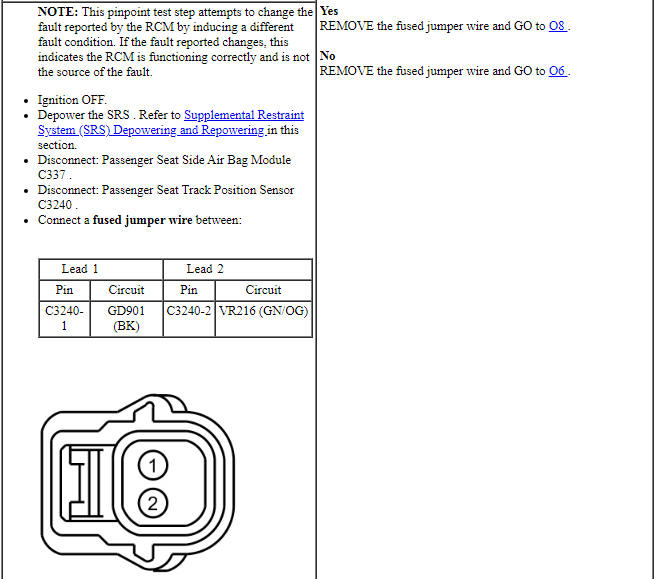
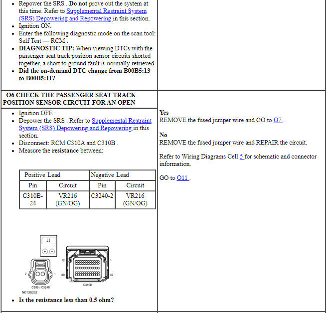
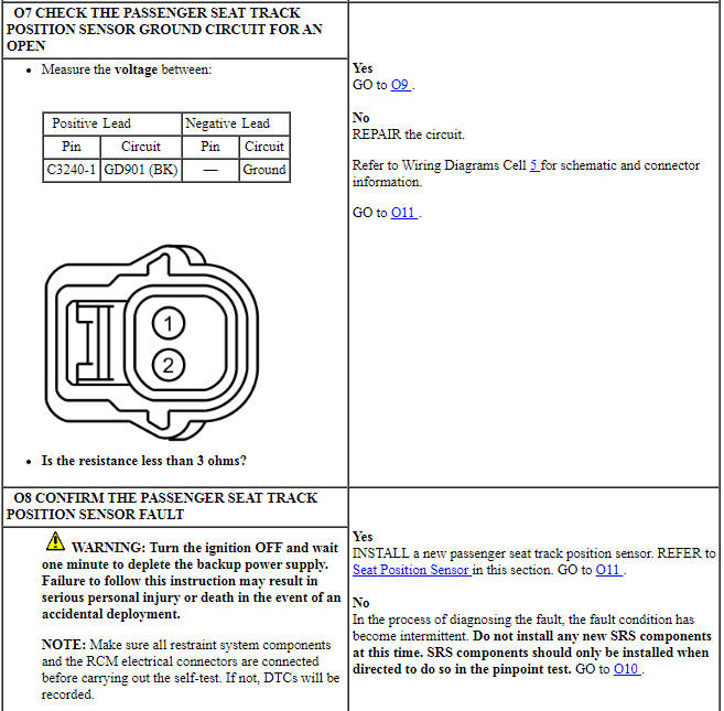
PINPOINT TEST O: DTCs B00C5:11, B00C5:12, B00C5:13 AND B00C5:1D
WARNING: Do not handle, move or change the original horizontal mounting position of the restraints control module (RCM) while the RCM is connected and the ignition switch is ON. Failure to follow this instruction may result in the accidental deployment of the Safety Canopy and cause serious personal injury or death.
WARNING: Never disassemble or tamper with seat belt deployable components, including pretensioners, load limiters and inflators. Never back probe deployable device electrical connectors. Tampering or back probing may cause an accidental deployment and result in personal injury or death.
WARNING: Never probe the electrical connectors on airbag, Safety Canopy or side air curtain assemblies. Failure to follow this instruction may result in the accidental deployment of these assemblies, which increases the risk of serious personal injury or death.
NOTICE: Use the correct probe adapter(s) from the Flex Probe Kit when taking measurements. Failure to use the correct probe adapter(s) may damage the connector.
NOTE: Most faults are due to connector and/or wiring concerns. Carry out a thorough inspection and verification before proceeding with the pinpoint test.
NOTE: Only disconnect or reconnect SRS components when instructed to do so within a pinpoint test step. Failure to follow this instruction may result in incorrect diagnosis of the SRS.
NOTE: Always make sure the correct SRS component is being installed. Parts released for other vehicles may not be compatible even if they appear physically similar. Check the part number listed in the parts catalog to make sure the correct component is being installed. If an incorrect SRS component is installed, DTCs may set.
NOTE: The SRS must be fully operational and free of faults before releasing the vehicle to the customer.
Pinpoint Test P: DTCs B11CF:11, B11CF:12, B11CF:13 and B11CF:1A
Diagnostic Overview
Diagnostics in this manual assume a certain skill level and knowledge of Ford-specific diagnostic practices. Refer to Diagnostic Methods in Section 100-00 for information about these practices.
Refer to Wiring Diagrams Cell 46, Supplemental Restraint System for schematic and connector information.
Normal Operation and Fault Conditions
The RCM monitors the passenger air bag module canister vent and circuits for the following faults:
- Resistance out of range
- Unexpected voltage
- Short to ground
- Faulted passenger air bag module canister vent
If a fault is detected, the RCM stores DTC B11CF:11, B11CF:12, B11CF:13 or B11CF:1A in memory and sends a message to the IPC module to illuminate the air bag warning indicator.
The RCM analyzes the deployment loop resistance to determine if a fault exists. The value displayed in the PID is the deployment loop resistance measured by the RCM. If the value displayed is lower or higher than the desired range (refer to diagram below), the RCM can set a DTC. As the deployment loop resistance drifts farther outside the desired range, the chance for a DTC increases. Small variations in resistance can occur due to the effect of road vibrations on terminal fit. Crimps and terminals can be affected by stress and harness movement and can cause an increase in resistance due to wire strain. These variables can result in an intermittent fault. For this reason, the test requires the PID value to be within the desired range before the fault is considered repaired, regardless if the module is reporting an on-demand DTC at the time of diagnosis. Following this direction helps make sure that minor changes in resistance do not create a repeat concern. This test uses process of elimination to diagnose each part of the deployment loop circuit including:
- Wiring
- Connections
- Passenger air bag module canister vent
- RCM

-
Visual Inspection and Diagnostic Pre-checks
- Inspect for damaged wiring harness(es).
- Inspect for loose or damaged connectors.
-
Possible Sources
- Wiring, terminals or connectors
- Passenger air bag module (includes canister vent)
- RCM
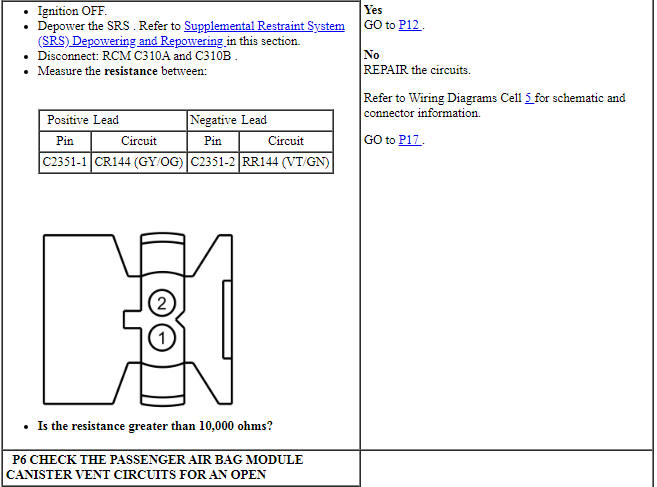
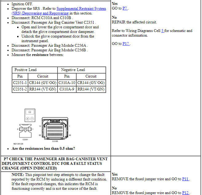
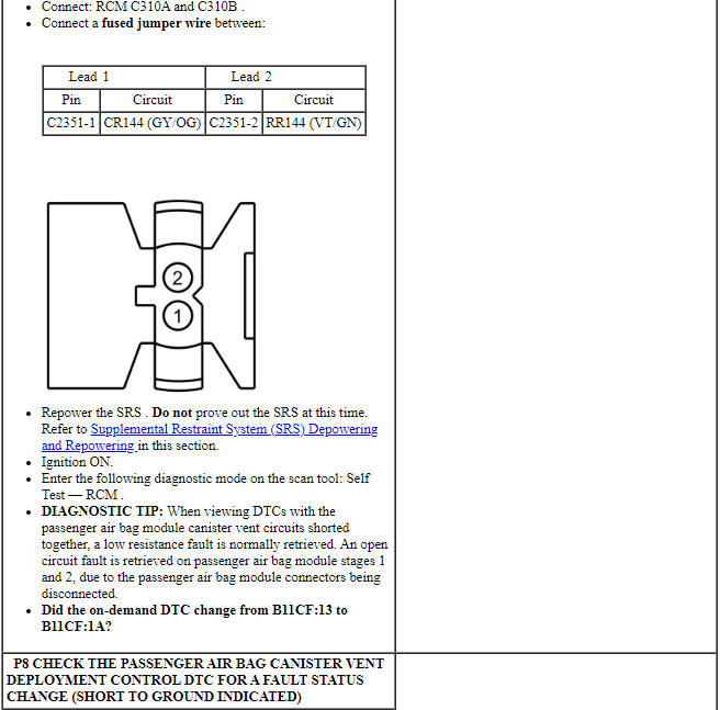
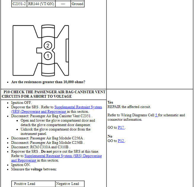
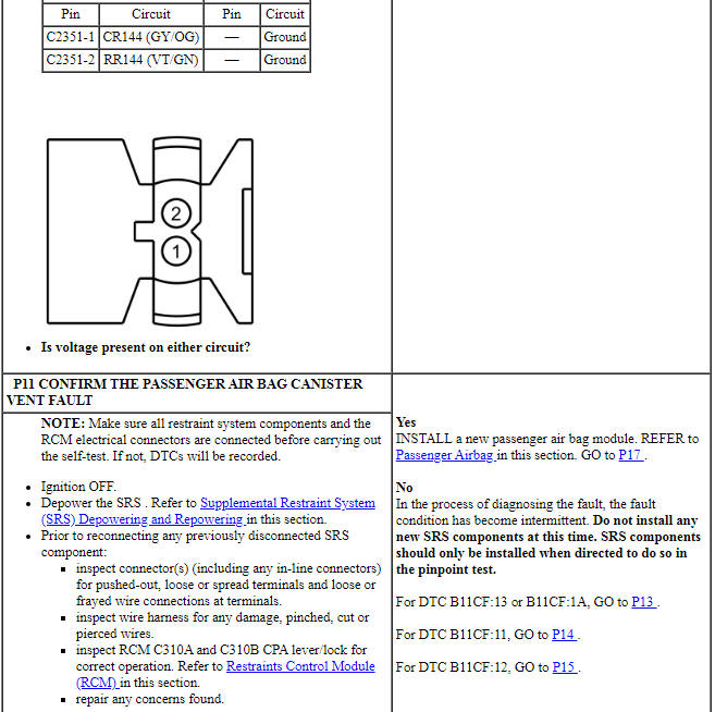
PINPOINT TEST P: DTCs B11CF:11, B11CF:12, B11CF:13 and B11CF:1A
WARNING: Do not handle, move or change the original horizontal mounting position of the restraints control module (RCM) while the RCM is connected and the ignition switch is ON. Failure to follow this instruction may result in the accidental deployment of the Safety Canopy and cause serious personal injury or death.
WARNING: Never probe the electrical connectors on airbag, Safety Canopy or side air curtain assemblies. Failure to follow this instruction may result in the accidental deployment of these assemblies, which increases the risk of serious personal injury or death.
WARNING: Never disassemble or tamper with seat belt deployable components, including pretensioners, load limiters and inflators. Never back probe deployable device electrical connectors. Tampering or back probing may cause an accidental deployment and result in personal injury or death.
NOTICE: Use the correct probe adapter(s) from the Flex Probe Kit when taking measurements. Failure to use the correct probe adapter(s) may damage the connector.
NOTE: Most faults are due to connector and/or wiring concerns. Carry out a thorough inspection and verification before proceeding with the pinpoint test.
NOTE: Only disconnect or reconnect SRS components when instructed to do so within a pinpoint test step. Failure to follow this instruction may result in incorrect diagnosis of the SRS.
NOTE: Always make sure the correct SRS component is being installed. Parts released for other vehicles may not be compatible even if they appear physically similar. Check the part number listed in the parts catalog to make sure the correct component is being installed. If an incorrect SRS component is installed, DTCs may set.
NOTE: The SRS must be fully operational and free of faults before releasing the vehicle to the customer.
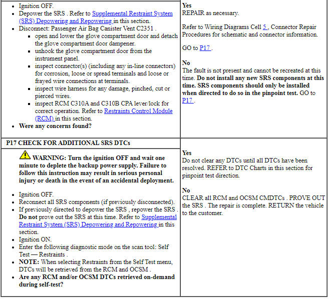
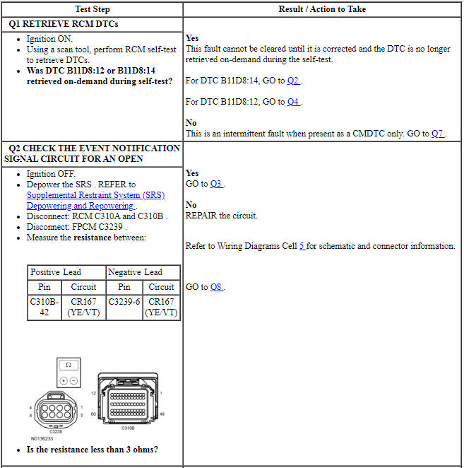
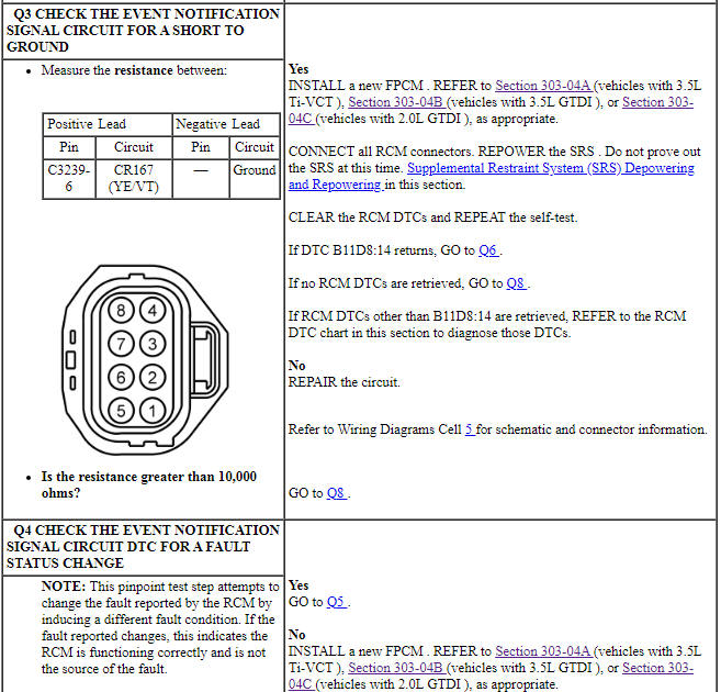
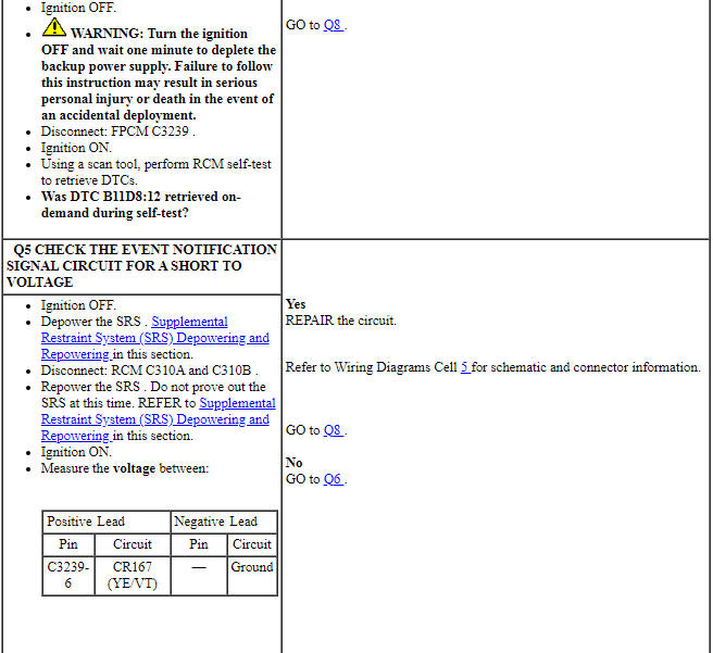
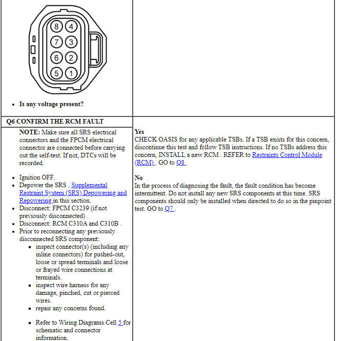
Pinpoint Test Q: DTCs B11D8:12 and B11D8:14
Diagnostic Overview
Diagnostics in this manual assume a certain skill level and knowledge of Ford-specific diagnostic practices. Refer to Diagnostic Methods in Section 100-00 for information about these practices.
Refer to Wiring Diagrams Cell 46, Supplemental Restraint System for schematic and connector information.
Normal Operation and Fault Conditions
The RCM transmits an event notification signal which communicates fuel cutoff status and SRS deployment status to the fuel pump control module. This allows the PCM to initiate fuel cut-off in the event of a crash.
The RCM monitors the event notification signal circuit for the following faults:
- Short to voltage
- Short to ground
- Open circuit
If a fault is detected, the RCM stores DTC B11D8:12 or B11D8:14 in memory. The air bag warning indicator will not be illuminated if B11D8:12 or B11D8:14 is set.
- DTC B11D8:12 (Restraint Event Notification: Circuit Short to Battery) - A fault is indicated when the RCM senses a short to voltage on the event notification signal circuit for more than 15 seconds.
- DTC B11D8:14 (Restraint Event Notification: Circuit Short to Ground or Open) - A fault is indicated when the RCM senses a short to ground or an open on the event notification signal circuit for more than 15 seconds.
-
Possible Sources
- Wiring, terminals or connectors
- FPCM
- RCM
PINPOINT TEST Q: DTCs B11D8:12 AND B11D8:14
WARNING: Do not handle, move or change the original horizontal mounting position of the restraints control module (RCM) while the RCM is connected and the ignition switch is ON. Failure to follow this instruction may result in the accidental deployment of the Safety Canopy and cause serious personal injury or death.
NOTICE: Use the correct probe adapter(s) from the Flex Probe Kit when taking measurements. Failure to use the correct probe adapter(s) may damage the connector.
NOTE: Most faults are due to connector and/or wiring concerns. Carry out a thorough inspection and verification before proceeding with the pinpoint test.
NOTE: Only disconnect or reconnect SRS components when instructed to do so within a pinpoint test step. Failure to follow this instruction may result in incorrect diagnosis of the SRS.
NOTE: Install new components only when directed to do so in the pinpoint test.
NOTE: Always make sure the correct SRS component is being installed. Parts released for other vehicles may not be compatible even if they appear physically similar. Check the part number listed in the parts catalog to make sure the correct component is being installed. If an incorrect SRS component is installed, DTCs may set.
NOTE: The SRS must be fully operational and free of faults before releasing the vehicle to the customer.
Pinpoint Test R: DTCs B1404:11, B1404:12, B1404:13 and B1404:1A
Diagnostic Overview
Diagnostics in this manual assume a certain skill level and knowledge of Ford-specific diagnostic practices. Refer to Diagnostic Methods in Section 100-00 for information about these practices.
Refer to Wiring Diagrams Cell 46, Supplemental Restraint System for schematic and connector information.
Normal Operation and Fault Conditions
The RCM continuously monitors the driver seat side air bag module and circuits for the following faults:
- Resistance out of range
- Unexpected voltage
- Short to ground
- Faulted driver seat side air bag module
If a fault is detected, the RCM stores DTC B1404:11, B1404:12, B1404:13 or B1404:1A in memory and sends a message to the IPC module to illuminate the air bag warning indicator.
The RCM analyzes the deployment loop resistance to determine if a fault exists. The value displayed in the PID is the deployment loop resistance measured by the RCM. If the value displayed is lower or higher than the desired range (refer to diagram below), the RCM can set a DTC. As the deployment loop resistance drifts farther outside the desired range, the chance for a DTC increases. Small variations in resistance can occur due to the effect of road vibrations on terminal fit. Crimps and terminals can be affected by stress and harness movement and can cause an increase in resistance due to wire strain. These variables can result in an intermittent fault. For this reason, the test requires the PID value to be within the desired range before the fault is considered repaired, regardless if the module is reporting an on-demand DTC at the time of diagnosis. Following this direction helps make sure that minor changes in resistance do not create a repeat concern. This test uses process of elimination to diagnose each part of the deployment loop circuit including:
- Wiring
- Connections
- Driver seat side air bag module
- RCM

-
Visual Inspection and Diagnostic Pre-checks
- Inspect for damaged wiring harness(es).
- Inspect for loose or damaged connectors.
-
Possible Sources
- Wiring, terminals or connectors
- Driver seat side air bag module
- RCM
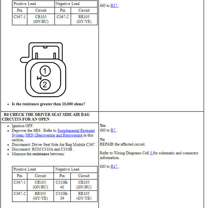
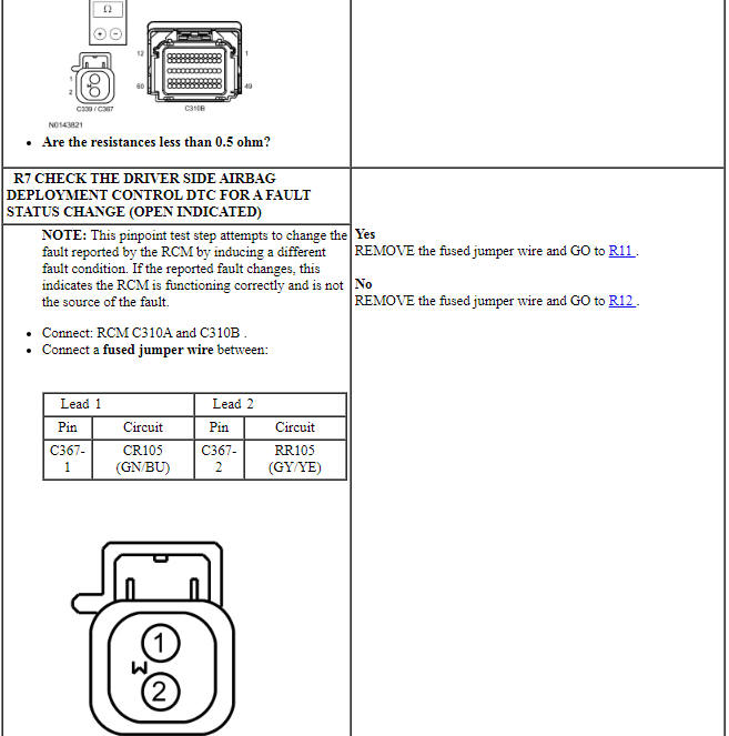
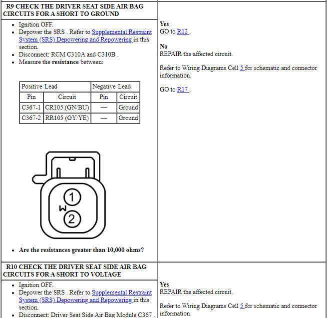
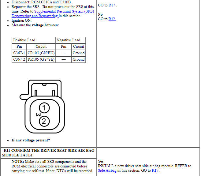
PINPOINT TEST R: DTCs B1404:11, B1404:12, B1404:13 AND B1404:1A
WARNING: Do not handle, move or change the original horizontal mounting position of the restraints control module (RCM) while the RCM is connected and the ignition switch is ON. Failure to follow this instruction may result in the accidental deployment of the Safety Canopy and cause serious personal injury or death.
WARNING: Never probe the electrical connectors on airbag, Safety Canopy or side air curtain assemblies. Failure to follow this instruction may result in the accidental deployment of these assemblies, which increases the risk of serious personal injury or death.
WARNING: Never disassemble or tamper with seat belt deployable components, including pretensioners, load limiters and inflators. Never back probe deployable device electrical connectors. Tampering or back probing may cause an accidental deployment and result in personal injury or death.
NOTICE: Use the correct probe adapter(s) from the Flex Probe Kit when taking measurements. Failure to use the correct probe adapter(s) may damage the connector.
NOTE: Most faults are due to connector and/or wiring concerns. Carry out a thorough inspection and verification before proceeding with the pinpoint test.
NOTE: Only disconnect or reconnect SRS components when instructed to do so within a pinpoint test step. Failure to follow this instruction may result in incorrect diagnosis of the SRS.
NOTE: Always make sure the correct SRS component is being installed. Parts released for other vehicles may not be compatible even if they appear physically similar. Check the part number listed in the parts catalog to make sure the correct component is being installed. If an incorrect SRS component is installed, DTCs may set.
NOTE: The SRS must be fully operational and free of faults before releasing the vehicle to the customer.
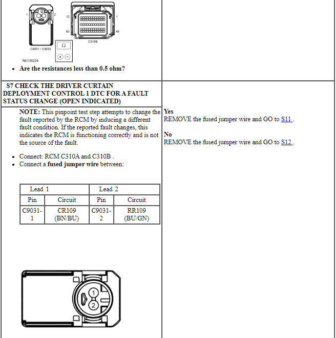
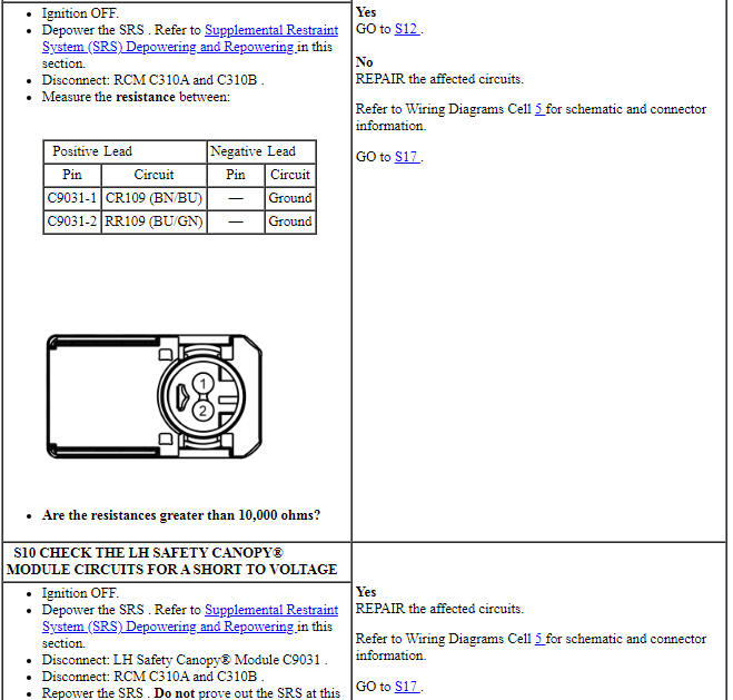
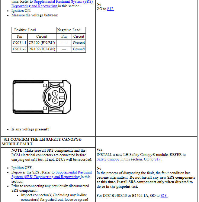
Pinpoint Test S: DTCs B1405:11, B1405:12, B1405:13 and B1405:1A
Diagnostic Overview
Diagnostics in this manual assume a certain skill level and knowledge of Ford-specific diagnostic practices. Refer to Diagnostic Methods in Section 100-00 for information about these practices.
Refer to Wiring Diagrams Cell 46, Supplemental Restraint System for schematic and connector information.
Normal Operation and Fault Conditions
The RCM continuously monitors the LH Safety Canopy module and circuits for the following faults:
- Resistance out of range
- Unexpected voltage
- Short to ground
- Faulted LH Safety Canopy module
If a fault is detected, the RCM stores DTC B1405:11, B1405:12, B1405:13 or B1405:1A in memory and sends a message to the IPC module to illuminate the air bag warning indicator.
The RCM analyzes the deployment loop resistance to determine if a fault exists. The value displayed in the PID is the deployment loop resistance measured by the RCM. If the value displayed is lower or higher than the desired range (refer to diagram below), the RCM can set a DTC. As the deployment loop resistance drifts farther outside the desired range, the chance for a DTC increases. Small variations in resistance can occur due to the effect of road vibrations on terminal fit. Crimps and terminals can be affected by stress and harness movement and can cause an increase in resistance due to wire strain. These variables can result in an intermittent fault. For this reason, the test requires the PID value to be within the desired range before the fault is considered repaired, regardless if the module is reporting an on-demand DTC at the time of diagnosis. Following this direction helps make sure that minor changes in resistance do not create a repeat concern. This test uses process of elimination to diagnose each part of the deployment loop circuit including:
- Wiring
- Connections
- Safety Canopy module
- RCM

-
Visual Inspection and Diagnostic Pre-checks
- Inspect for damaged wiring harness(es).
- Inspect for loose or damaged connectors.
-
Possible Sources
- Wiring, terminals or connectors
- Safety Canopy module
- RCM
PINPOINT TEST S: DTCs B1405:11, B1405:12, B1405:13 AND B1405:1A
WARNING: Do not handle, move or change the original horizontal mounting position of the restraints control module (RCM) while the RCM is connected and the ignition switch is ON. Failure to follow this instruction may result in the accidental deployment of the Safety Canopy and cause serious personal injury or death.
WARNING: Never probe the electrical connectors on airbag, Safety Canopy or side air curtain assemblies. Failure to follow this instruction may result in the accidental deployment of these assemblies, which increases the risk of serious personal injury or death.
WARNING: Never disassemble or tamper with seat belt deployable components, including pretensioners, load limiters and inflators. Never back probe deployable device electrical connectors. Tampering or back probing may cause an accidental deployment and result in personal injury or death.
NOTICE: Use the correct probe adapter(s) from the Flex Probe Kit when taking measurements. Failure to use the correct probe adapter(s) may damage the connector.
NOTE: Most faults are due to connector and/or wiring concerns. Carry out a thorough inspection and verification before proceeding with the pinpoint test.
NOTE: Only disconnect or reconnect SRS components when instructed to do so within a pinpoint test step. Failure to follow this instruction may result in incorrect diagnosis of the SRS.
NOTE: Always make sure the correct SRS component is being installed. Parts released for other vehicles may not be compatible even if they appear physically similar. Check the part number listed in the parts catalog to make sure the correct component is being installed. If an incorrect SRS component is installed, DTCs may set.
NOTE: The SRS must be fully operational and free of faults before releasing the vehicle to the customer.


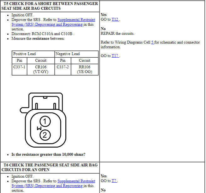
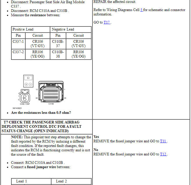
-
Visual Inspection and Diagnostic Pre-checks
- Inspect for damaged wiring harness(es).
- Inspect for loose or damaged connectors.
-
Possible Sources
- Wiring, terminals or connectors
- Passenger seat side air bag module
- RCM
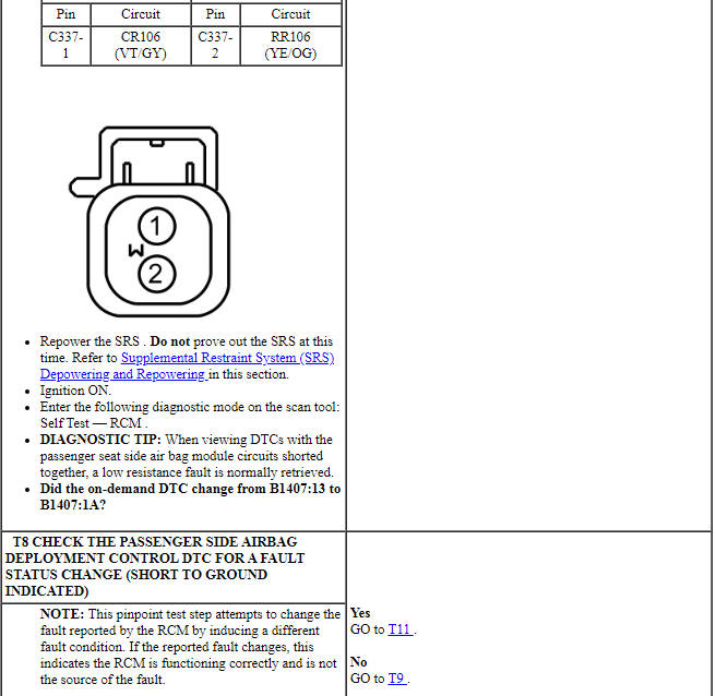
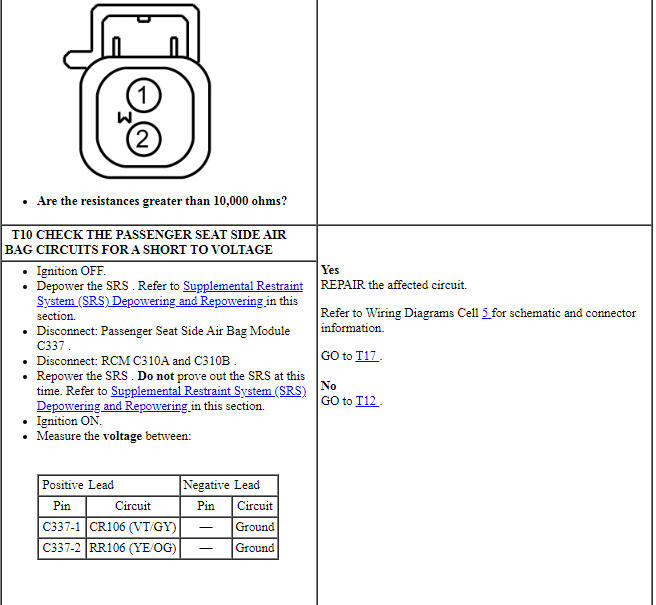
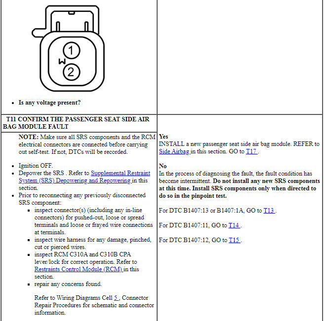
PINPOINT TEST T: DTCs B1407:11, B1407:12, B1407:13 AND B1407:1A
WARNING: Do not handle, move or change the original horizontal mounting position of the restraints control module (RCM) while the RCM is connected and the ignition switch is ON. Failure to follow this instruction may result in the accidental deployment of the Safety Canopy and cause serious personal injury or death.
WARNING: Never probe the electrical connectors on airbag, Safety Canopy or side air curtain assemblies. Failure to follow this instruction may result in the accidental deployment of these assemblies, which increases the risk of serious personal injury or death.
WARNING: Never disassemble or tamper with seat belt deployable components, including pretensioners, load limiters and inflators. Never back probe deployable device electrical connectors. Tampering or back probing may cause an accidental deployment and result in personal injury or death.
NOTICE: Use the correct probe adapter(s) from the Flex Probe Kit when taking measurements. Failure to use the correct probe adapter(s) may damage the connector.
NOTE: Most faults are due to connector and/or wiring concerns. Carry out a thorough inspection and verification before proceeding with the pinpoint test.
NOTE: Only disconnect or reconnect SRS components when instructed to do so within a pinpoint test step. Failure to follow this instruction may result in incorrect diagnosis of the SRS.
NOTE: Always make sure the correct SRS component is being installed. Parts released for other vehicles may not be compatible even if they appear physically similar. Check the part number listed in the parts catalog to make sure the correct component is being installed. If an incorrect SRS component is installed, DTCs may set.
NOTE: The SRS must be fully operational and free of faults before releasing the vehicle to the customer.
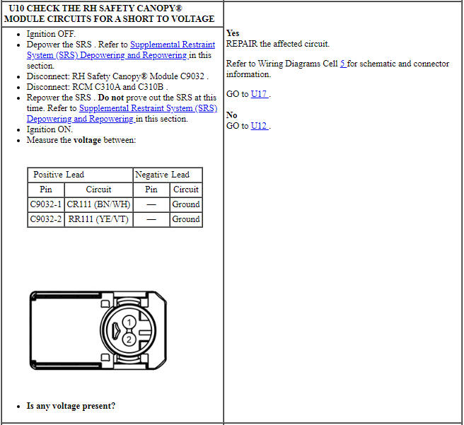
-
Visual Inspection and Diagnostic Pre-checks
- Inspect for damaged wiring harness(es).
- Inspect for loose or damaged connectors.
-
Possible Sources
- Wiring, terminals or connectors
- RH Safety Canopy module
- RCM
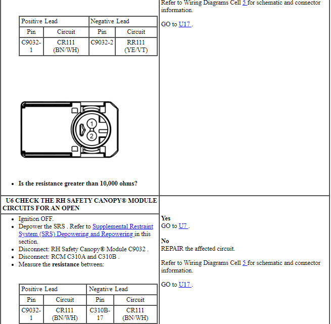
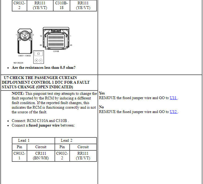
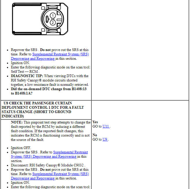
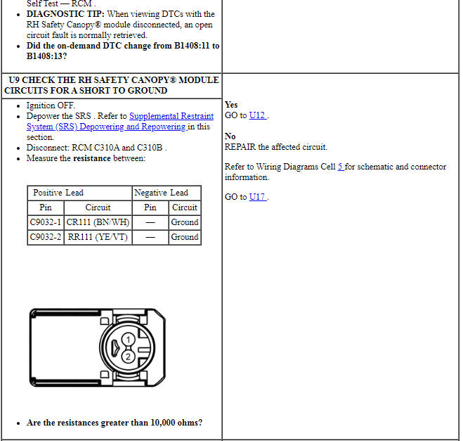
PINPOINT TEST U: DTCs B1408:11, B1408:12, B1408:13 AND B1408:1A
WARNING: Do not handle, move or change the original horizontal mounting position of the restraints control module (RCM) while the RCM is connected and the ignition switch is ON. Failure to follow this instruction may result in the accidental deployment of the Safety Canopy and cause serious personal injury or death.
WARNING: Never probe the electrical connectors on airbag, Safety Canopy or side air curtain assemblies. Failure to follow this instruction may result in the accidental deployment of these assemblies, which increases the risk of serious personal injury or death.
WARNING: Never disassemble or tamper with seat belt deployable components, including pretensioners, load limiters and inflators. Never back probe deployable device electrical connectors. Tampering or back probing may cause an accidental deployment and result in personal injury or death.
NOTICE: Use the correct probe adapter(s) from the Flex Probe Kit when taking measurements. Failure to use the correct probe adapter(s) may damage the connector.
NOTE: Most faults are due to connector and/or wiring concerns. Carry out a thorough inspection and verification before proceeding with the pinpoint test.
NOTE: Only disconnect or reconnect SRS components when instructed to do so within a pinpoint test step. Failure to follow this instruction may result in incorrect diagnosis of the SRS.
NOTE: Always make sure the correct SRS component is being installed. Parts released for other vehicles may not be compatible even if they appear physically similar. Check the part number listed in the parts catalog to make sure the correct component is being installed. If an incorrect SRS component is installed, DTCs may set.
NOTE: The SRS must be fully operational and free of faults before releasing the vehicle to the customer.
Pinpoint Test V: DTCs B1413:11 or B1413:93
Diagnostic Overview
Diagnostics in this manual assume a certain skill level and knowledge of Ford-specific diagnostic practices. Refer to Diagnostic Methods in Section 100-00 for information about these practices.
Refer to Wiring Diagrams Cell 46, Supplemental Restraint System for schematic and connector information.
Normal Operation and Fault Conditions
The RCM monitors the LH front impact severity sensor and circuits for the following faults:
- Open circuit
- Short to voltage
- Short to ground
- Faulted LH front impact severity sensor
If a fault is detected, the RCM stores DTC B1413:11 or B1413:93 in memory and sends a message to the IPC module to illuminate the air bag warning indicator.
- B1413:11 (Driver Frontal Restraints Sensor: Circuit Short to Ground) - A fault is indicated when the RCM senses a short to ground on the LH front impact severity sensor feed circuit.
- B1413:93 (Driver Frontal Restraints Sensor: No Operation) - A fault is indicated when the RCM senses a faulted LH front impact severity sensor, a short to voltage on the feed circuit or an open feed or return circuit.
-
Visual Inspection and Diagnostic Pre-checks
- Inspect for a damaged LH front impact severity sensor.
- Inspect the LH front impact severity sensor mounting and orientation.
- Inspect for damaged wiring harness(es).
- Inspect for loose or damaged connectors.
-
Possible Sources
- Wiring, terminals or connectors
- LH front impact severity sensor
- RCM
PINPOINT TEST V: DTCs B1413:11 OR B1413:93
WARNING: Do not handle, move or change the original horizontal mounting position of the restraints control module (RCM) while the RCM is connected and the ignition switch is ON. Failure to follow this instruction may result in the accidental deployment of the Safety Canopy and cause serious personal injury or death.
NOTICE: Use the correct probe adapter(s) from the Flex Probe Kit when taking measurements. Failure to use the correct probe adapter(s) may damage the connector.
NOTE: Most faults are due to connector and/or wiring concerns. Carry out a thorough inspection and verification before proceeding with the pinpoint test.
NOTE: Only disconnect or reconnect SRS components when instructed to do so within a pinpoint test step. Failure to follow this instruction may result in incorrect diagnosis of the SRS.
NOTE: The SRS must be fully operational and free of faults before releasing the vehicle to the customer.
NOTE: Always make sure the correct SRS component is being installed. Parts released for other vehicles may not be compatible even if they appear physically similar. Check the part number listed in the parts catalog to make sure the correct component is being installed. If an incorrect SRS component is installed, DTCs may set.
NOTE: Do not probe any impact sensor. The impact sensor cannot be tested using a multi-meter.
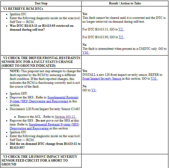
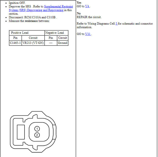
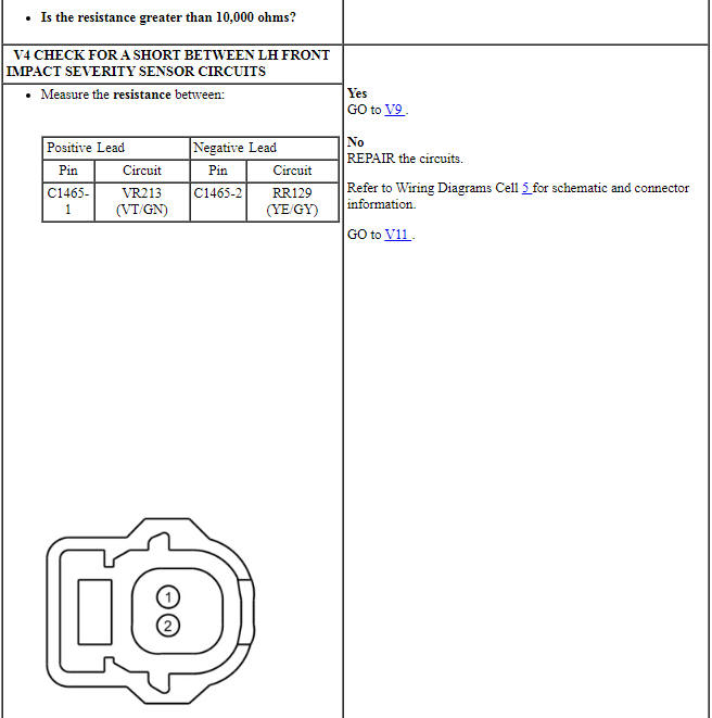
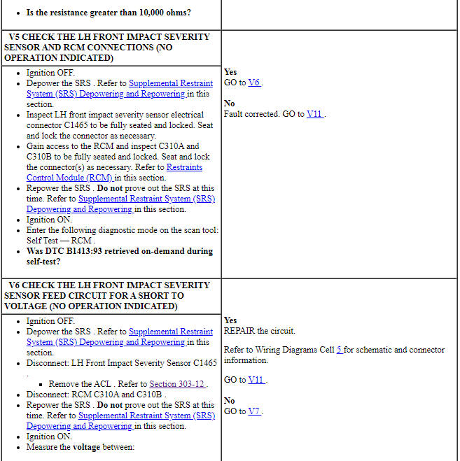
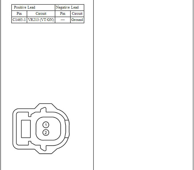
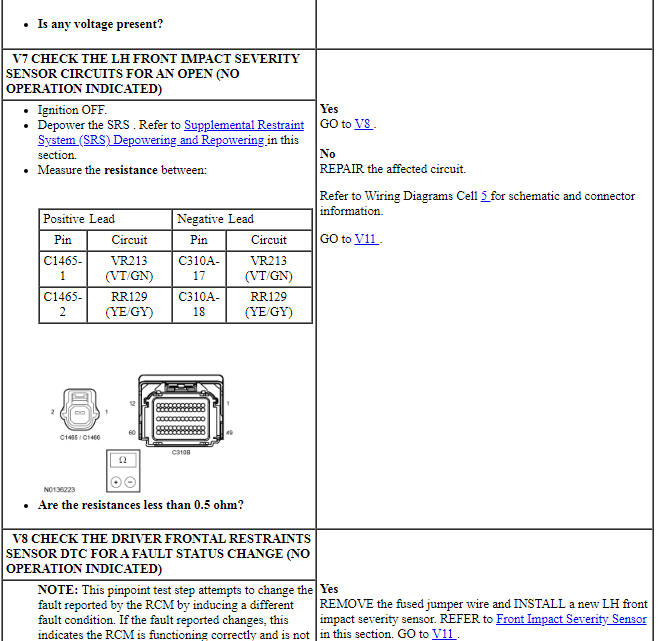
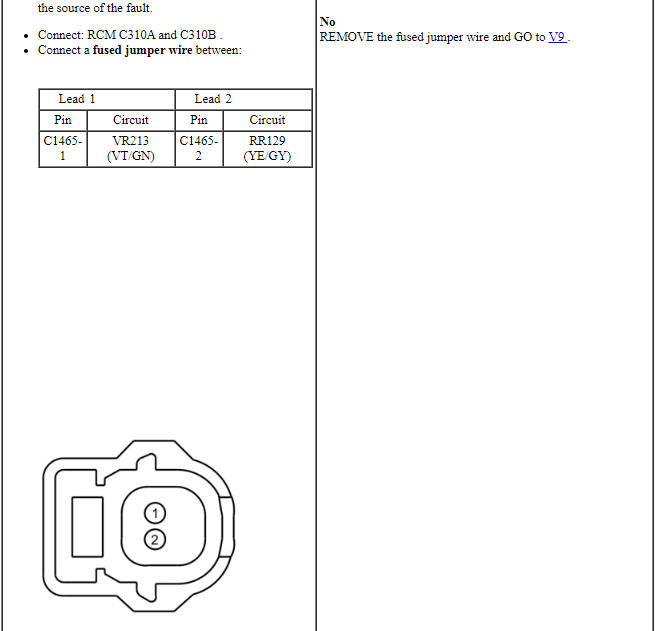
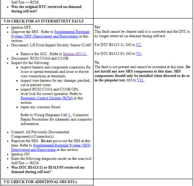
Pinpoint Test W: DTCs B1414:11, B1414:93, B1419:11 and B1419:93
Diagnostic Overview
Diagnostics in this manual assume a certain skill level and knowledge of Ford-specific diagnostic practices. Refer to Diagnostic Methods in Section 100-00 for information about these practices.
Refer to Wiring Diagrams Cell 46, Supplemental Restraint System for schematic and connector information.
Normal Operation and Fault Conditions
The RCM monitors the driver front door and second row RH (C-pillar) side impact sensors and circuits for the following faults:
- Open circuit
- Short to voltage
- Short to ground
- Faulted driver front door side impact sensor
- Faulted second row RH side impact sensor
If a fault is detected, the RCM stores DTC B1414:11, B1414:93, B1419:11 or B1419:93 in memory and sends a message to the IPC module to illuminate the air bag warning indicator.
The RCM communicates with each impact sensor, if the RCM is unable to communicate with the sensor, a DTC will be stored in memory. A CMDTC no operation (failure type :93) can be set by a short to voltage on the return circuit of the impact sensor.
NOTE: A short to ground on either impact sensor feed circuit sets DTCs B1414:11 and B1419:11.
A short to voltage on either impact sensor feed or return circuit sets DTCs B1414:93 and B1419:93.
-
Visual Inspection and Diagnostic Pre-checks
- Inspect for a damaged driver front door side impact sensor.
- Inspect for a damaged second row RH side impact sensor.
- Inspect for damaged wiring harness(es).
- Inspect for loose or damaged connectors.
-
Possible Sources
- Wiring, terminals or connectors
- Driver front door side impact sensor
- Second row RH side impact sensor
- RCM
PINPOINT TEST W: DTCs B1414:11, B1414:93, B1419:11 AND B1419:93
WARNING: Do not handle, move or change the original horizontal mounting position of the restraints control module (RCM) while the RCM is connected and the ignition switch is ON. Failure to follow this instruction may result in the accidental deployment of the Safety Canopy and cause serious personal injury or death.
NOTICE: Use the correct probe adapter(s) from the Flex Probe Kit when taking measurements. Failure to use the correct probe adapter(s) may damage the connector.
NOTE: Most faults are due to connector and/or wiring concerns. Carry out a thorough inspection and verification before proceeding with the pinpoint test.
NOTE: Only disconnect or reconnect SRS components when instructed to do so within a pinpoint test step. Failure to follow this instruction may result in incorrect diagnosis of the SRS.
NOTE: The SRS must be fully operational and free of faults before releasing the vehicle to the customer.
NOTE: Always make sure the correct SRS component is being installed. Parts released for other vehicles may not be compatible even if they appear physically similar. Check the part number listed in the parts catalog to make sure the correct component is being installed. If an incorrect SRS component is installed, DTCs may set.
NOTE: Do not probe any impact sensor. The impact sensor cannot be tested using a multi-meter.
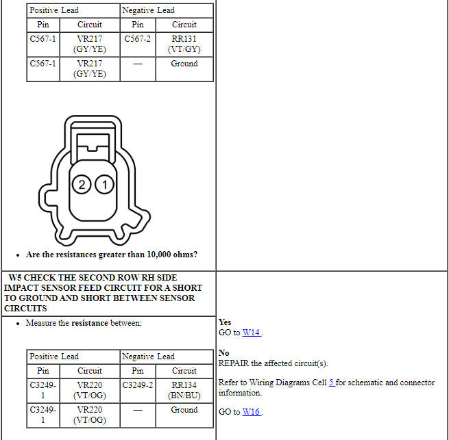
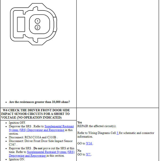
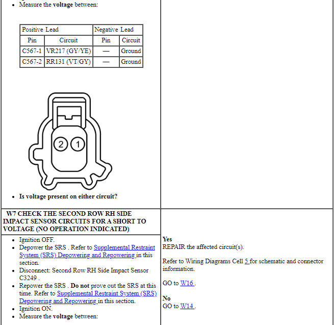
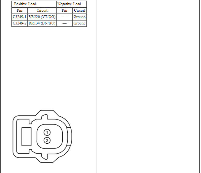
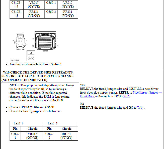
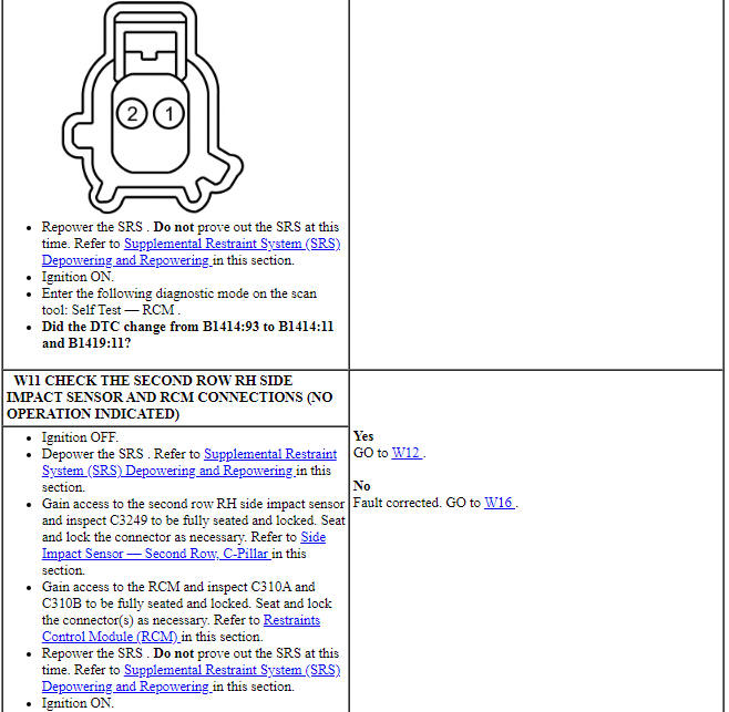
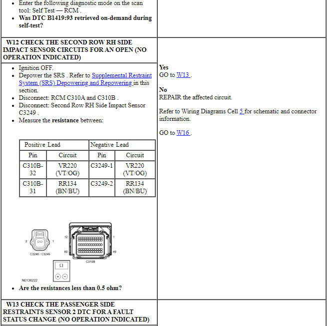
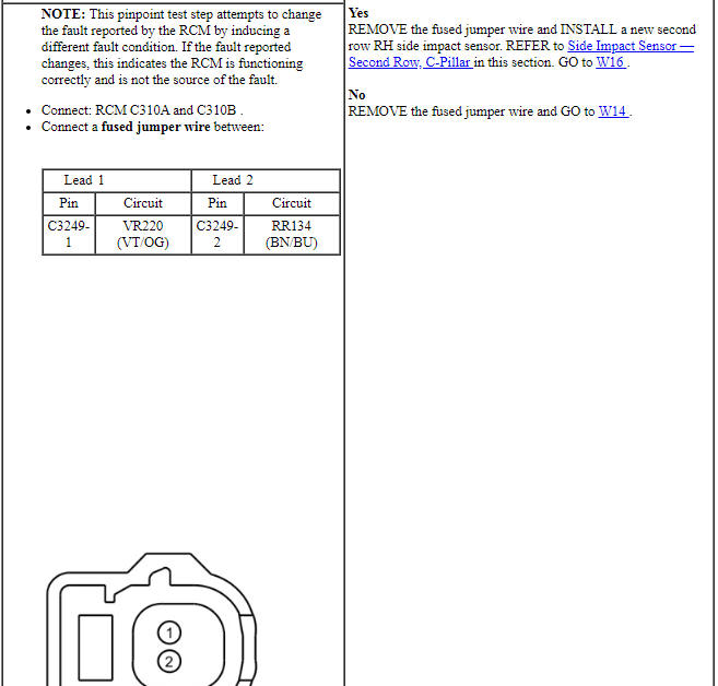

Pinpoint Test X: DTCs B1415:11, B1415:93, B1418:11 and B1418:93
Diagnostic Overview
Diagnostics in this manual assume a certain skill level and knowledge of Ford-specific diagnostic practices. Refer to Diagnostic Methods in Section 100-00 for information about these practices.
Refer to Wiring Diagrams Cell 46, Supplemental Restraint System for schematic and connector information.
Normal Operation and Fault Conditions
The RCM monitors the second row LH (C-pillar) and passenger front door side impact sensors and circuits for the following faults:
- Open circuit
- Short to voltage
- Short to ground
- Faulted second row LH side impact sensor
- Faulted passenger front door side impact sensor
If a fault is detected, the RCM stores DTC B1415:11, B1415:93, B1418:11 or B1418:93 in memory and sends a message to the IPC module to illuminate the air bag warning indicator.
The RCM communicates with each impact sensor, if the RCM is unable to communicate with the sensor, a DTC will be stored in memory. A CMDTC no operation (failure type :93) can be set by a short to voltage on the return circuit of the impact sensor.
NOTE: A short to ground on either impact sensor feed circuit sets DTCs B1415:11 and B1418:11.
A short to voltage on either impact sensor feed or return circuit sets DTCs B1415:93 and B1418:93.
-
Visual Inspection and Diagnostic Pre-checks
- Inspect for a damaged passenger front door side impact sensor.
- Inspect for a damaged second row LH side impact sensor.
- Inspect for damaged wiring harness(es).
- Inspect for loose or damaged connectors.
-
Possible Sources
- Wiring, terminals or connectors
- Passenger front door side impact sensor
- Second row LH side impact sensor
- RCM
PINPOINT TEST X: DTCs B1415:11, B1415:93, B1418:11 AND B1418:93
WARNING: Do not handle, move or change the original horizontal mounting position of the restraints control module (RCM) while the RCM is connected and the ignition switch is ON. Failure to follow this instruction may result in the accidental deployment of the Safety Canopy and cause serious personal injury or death.
NOTICE: Use the correct probe adapter(s) from the Flex Probe Kit when taking measurements. Failure to use the correct probe adapter(s) may damage the connector.
NOTE: Most faults are due to connector and/or wiring concerns. Carry out a thorough inspection and verification before proceeding with the pinpoint test.
NOTE: Only disconnect or reconnect SRS components when instructed to do so within a pinpoint test step. Failure to follow this instruction may result in incorrect diagnosis of the SRS.
NOTE: The SRS must be fully operational and free of faults before releasing the vehicle to the customer.
NOTE: Always make sure the correct SRS component is being installed. Parts released for other vehicles may not be compatible even if they appear physically similar. Check the part number listed in the parts catalog to make sure the correct component is being installed. If an incorrect SRS component is installed, DTCs may set.
NOTE: Do not probe any impact sensor. The impact sensor cannot be tested using a multi-meter.
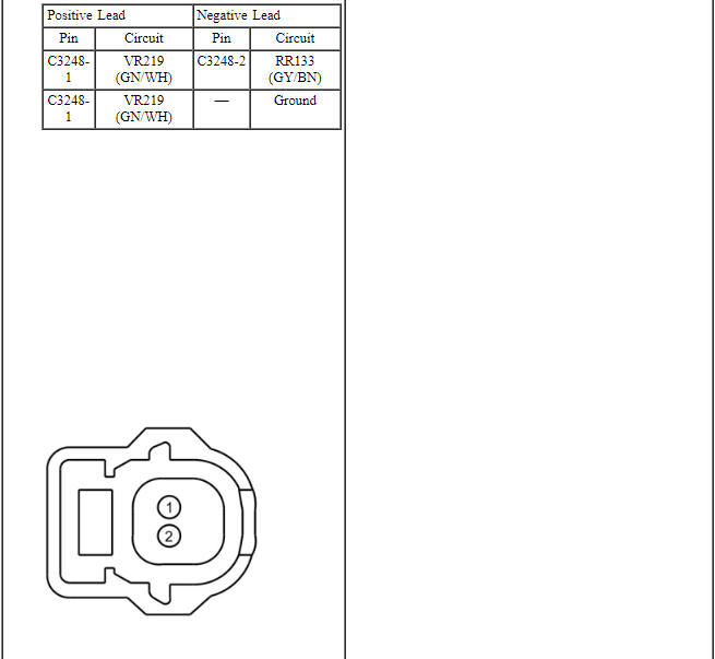
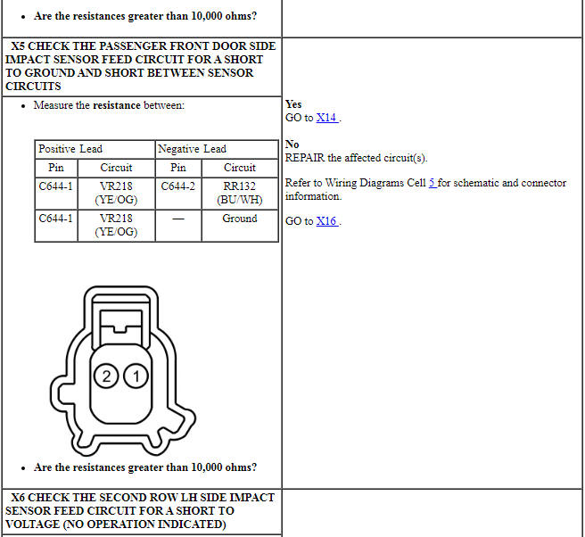
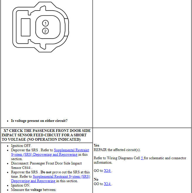
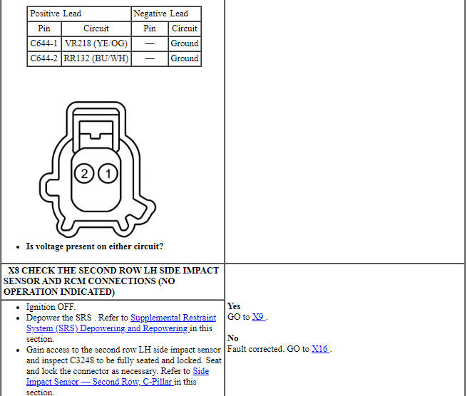
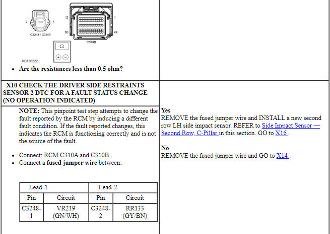
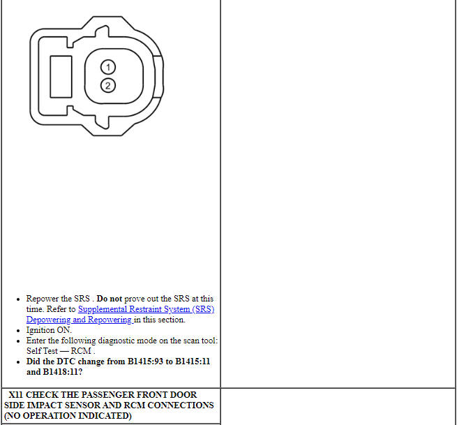
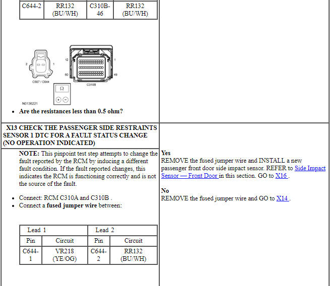
Pinpoint Test Y: DTCs B1417:11 and B1417:93
Diagnostic Overview
Diagnostics in this manual assume a certain skill level and knowledge of Ford-specific diagnostic practices. Refer to Diagnostic Methods in Section 100-00 for information about these practices.
Refer to Wiring Diagrams Cell 46, Supplemental Restraint System for schematic and connector information.
Normal Operation and Fault Conditions
The RCM monitors the RH front impact severity sensor and circuits for the following faults:
- Open circuit
- Short to voltage
- Short to ground
- Faulted RH front impact severity sensor
If a fault is detected, the RCM stores DTC B1417:11 or B1417:93 in memory and sends a message to the IPC module to illuminate the air bag warning indicator.
- B1417:11 (Right Frontal Restraints Sensor: Circuit Short to Ground) - A fault is indicated when the RCM senses a short to ground on the RH front impact severity sensor feed circuit.
- B1417:93 (Right Frontal Restraints Sensor: No Operation) - A fault is indicated when the RCM senses a faulted sensor, a short to voltage on the feed circuit or an open feed or return circuit.
-
Visual Inspection and Diagnostic Pre-checks
- Inspect for a damaged RH front impact severity sensor.
- Inspect the RH front impact severity sensor mounting orientation.
- Inspect for damaged wiring harness(es).
- Inspect for loose or damaged connectors.
-
Possible Sources
- Wiring, terminals or connectors
- RH front impact severity sensor
- RCM
PINPOINT TEST Y: DTCs B1417:11 AND B1417:93
WARNING: Do not handle, move or change the original horizontal mounting position of the restraints control module (RCM) while the RCM is connected and the ignition switch is ON. Failure to follow this instruction may result in the accidental deployment of the Safety Canopy and cause serious personal injury or death.
NOTICE: Use the correct probe adapter(s) from the Flex Probe Kit when taking measurements. Failure to use the correct probe adapter(s) may damage the connector.
NOTE: Most faults are due to connector and/or wiring concerns. Carry out a thorough inspection and verification before proceeding with the pinpoint test.
NOTE: Only disconnect or reconnect SRS components when instructed to do so within a pinpoint test step. Failure to follow this instruction may result in incorrect diagnosis of the SRS.
NOTE: The SRS must be fully operational and free of faults before releasing the vehicle to the customer.
NOTE: Always make sure the correct SRS component is being installed. Parts released for other vehicles may not be compatible even if they appear physically similar. Check the part number listed in the parts catalog to make sure the correct component is being installed. If an incorrect SRS component is installed, DTCs may set.
NOTE: Do not probe any impact sensor. The impact sensor cannot be tested using a multi-meter.
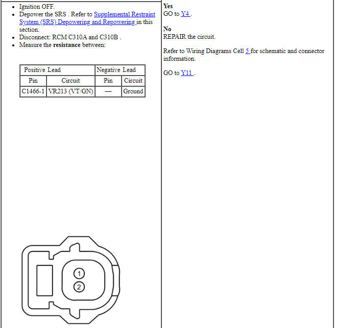
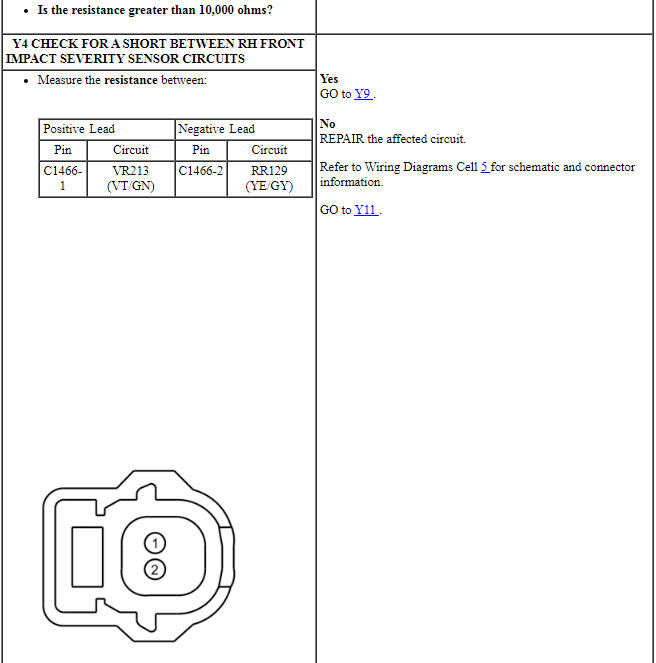
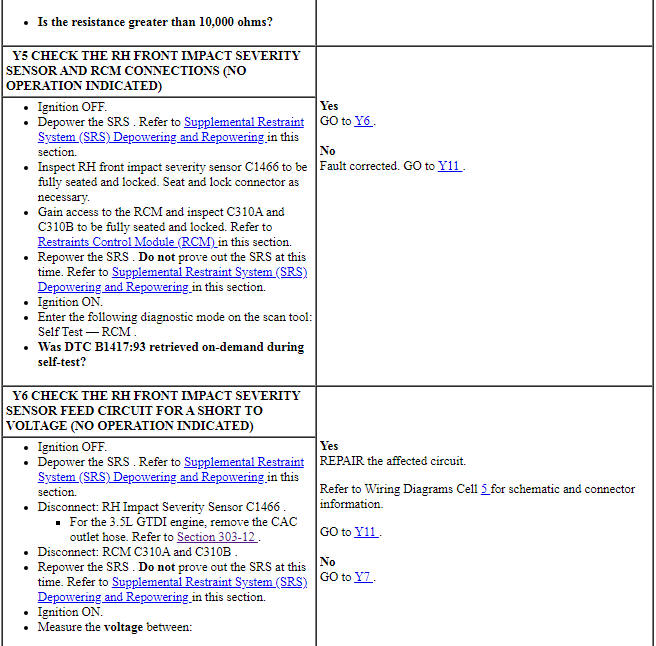
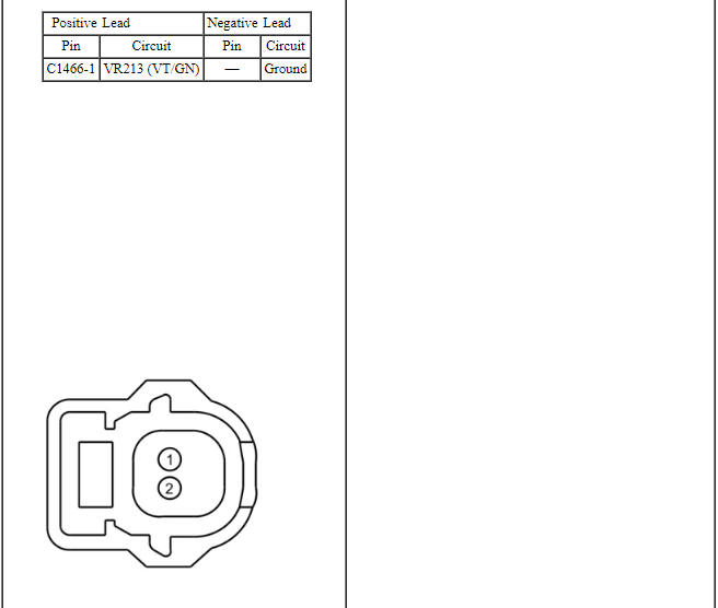
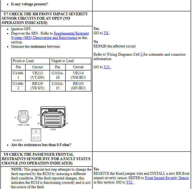
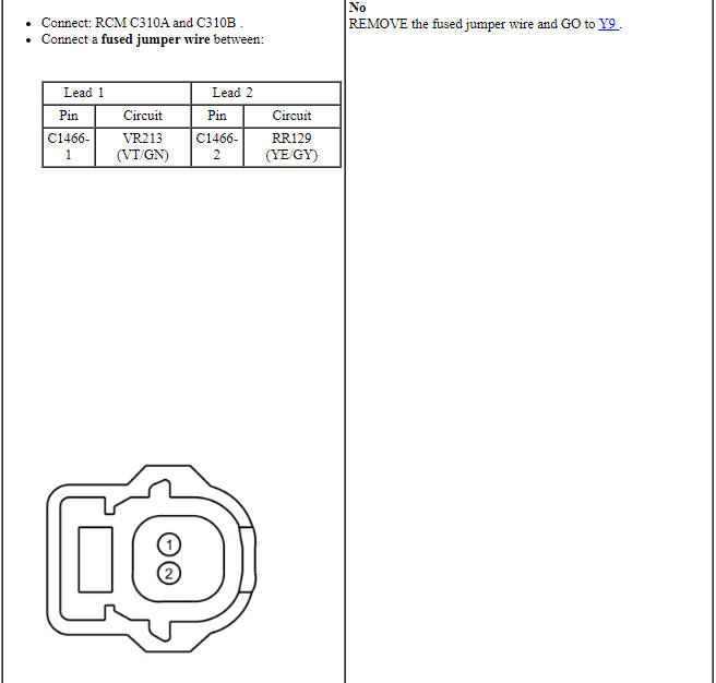
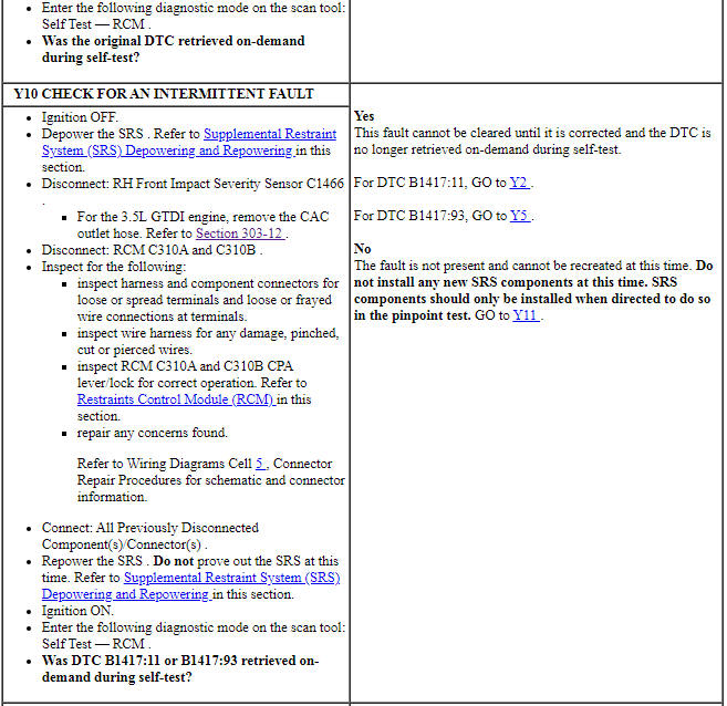
Pinpoint Test Z: DTCs B0001:2B, B0002:2B, B0005:2B, B0010:2B, B0011:2B, B0050:2B, B0052:2B, B0070:2B, B0072:2B, B007E:2B, B007F:2B, B0082:2B, B00B5:2B, B00C5:2B, B11CF:2B, B1404:2B, B1405:2B, B1407:2B and B1408:2B
Diagnostic Overview
Diagnostics in this manual assume a certain skill level and knowledge of Ford-specific diagnostic practices. Refer to Diagnostic Methods in Section 100-00 for information about these practices.
Refer to Wiring Diagrams Cell 46, Supplemental Restraint System for schematic and connector information.
Normal Operation and Fault Conditions
The RCM monitors all deployable device and sensor circuits for a signal cross coupled (short) between circuits. If the RCM detects a short between the circuits of one device and another device, it stores a DTC for each of the signal cross coupled faults in memory. The RCM sends a message to the IPC to illuminate the air bag warning indicator. When a normal loop fault is present (one loop is either shorted to battery/ground, open circuit or low resistance), then signal cross coupled diagnostics will not be active. The signal cross coupled diagnostics resume once the normal loop fault is repaired.
-
Visual Inspection and Diagnostic Pre-Checks
- Inspect the affected wiring harness(es) for damage, if accessible.
-
Possible Sources
- Wiring, terminals or connectors
- RCM
PINPOINT TEST Z: B0001:2B, B0002:2B, B0005:2B, B0010:2B, B0011:2B, B0050:2B, B0052:2B, B0070:2B, B0072:2B, B007E:2B, B007F:2B, B0082:2B, B00B5:2B, B00C5:2B, B11CF:2B, B1404:2B, B1405:2B, B1407:2B AND B1408:2B
WARNING: Do not handle, move or change the original horizontal mounting position of the restraints control module (RCM) while the RCM is connected and the ignition switch is ON. Failure to follow this instruction may result in the accidental deployment of the Safety Canopy and cause serious personal injury or death.
WARNING: Never probe the electrical connectors on airbag, Safety Canopy or side air curtain assemblies. Failure to follow this instruction may result in the accidental deployment of these assemblies, which increases the risk of serious personal injury or death.
WARNING: Never disassemble or tamper with seat belt deployable components, including pretensioners, load limiters and inflators. Never back probe deployable device electrical connectors. Tampering or back probing may cause an accidental deployment and result in personal injury or death.
NOTICE: Use the correct probe adapter(s) from the Flex Probe Kit when taking measurements. Failure to use the correct probe adapter(s) may damage the connector.
NOTE: Most faults are due to connector and/or wiring concerns. Carry out a thorough inspection and verification before proceeding with the pinpoint test.
NOTE: The SRS must be fully operational and free of faults before releasing the vehicle to the customer.
NOTE: Only disconnect or reconnect SRS components when instructed to do so within a pinpoint test step. Failure to follow this instruction may result in incorrect diagnosis of the SRS.
NOTE: Always make sure the correct SRS component is being installed. Parts released for other vehicles may not be compatible even if they appear physically similar. Check the part number listed in the parts catalog to make sure the correct component is being installed. If an incorrect SRS component is installed, DTCs may set.
NOTE: Most faults are due to connector and/or wiring concerns. Carry out a thorough inspection and verification before proceeding with the pinpoint test.

Pinpoint Test AA: DTCs B0001:4A, B0002:4A, B0005:4A, B0010:4A, B0011:4A, B0050:4A, B0052:4A, B0070:4A, B0072:4A, B007E:4A, B007F:4A, B00B5:4A, B00C5:4A, B11CF:4A, B1404:4A, B1405:4A, B1407:4A, B1408:4A, B1413:4A, B1414:4A, B1415:4A, B1417:4A, B1418:4A, B1419:4A, B1469:4A and B146A:4A
Diagnostic Overview
Diagnostics in this manual assume a certain skill level and knowledge of Ford-specific diagnostic practices. Refer to Diagnostic Methods in Section 100-00 for information about these practices.
Refer to Wiring Diagrams Cell 46, Supplemental Restraint System for schematic and connector information.
Normal Operation and Fault Conditions
The RCM monitors all SRS device connections. If the RCM detects a connection or device connected that is not stored in memory or is not configured for the component, the RCM will set a DTC and send a message to the IPC module to illuminate air bag warning indicator.
-
Possible Sources
- Incorrect ABS module
- Incorrect OCSM
- Incorrect RCM
- RCM not configured
PINPOINT TEST AA: DTCs B0001:4A, B0002:4A, B0005:4A, B0010:4A, B0011:4A, B0050:4A, B0052:4A, B0070:4A, B0072:4A, B007E:4A, B007F:4A, B00B5:4A, B00C5:4A, B11CF:4A, B1404:4A, B1405:4A, B1407:4A, B1408:4A, B1413:4A, B1414:4A, B1415:4A, B1417:4A, B1418:4A, B1419:4A, B1469:4A AND B146A:4A
WARNING: Do not handle, move or change the original horizontal mounting position of the restraints control module (RCM) while the RCM is connected and the ignition switch is ON. Failure to follow this instruction may result in the accidental deployment of the Safety Canopy and cause serious personal injury or death.
WARNING: Never probe the electrical connectors on airbag, Safety Canopy or side air curtain assemblies. Failure to follow this instruction may result in the accidental deployment of these assemblies, which increases the risk of serious personal injury or death.
WARNING: Never disassemble or tamper with seat belt deployable components, including pretensioners, load limiters and inflators. Never back probe deployable device electrical connectors. Tampering or back probing may cause an accidental deployment and result in personal injury or death.
NOTICE: Use the correct probe adapter(s) from the Flex Probe Kit when taking measurements. Failure to use the correct probe adapter(s) may damage the connector.
NOTE: Most faults are due to connector and/or wiring concerns. Carry out a thorough inspection and verification before proceeding with the pinpoint test.
NOTE: The SRS must be fully operational and free of faults before releasing the vehicle to the customer.
NOTE: Only disconnect or reconnect SRS components when instructed to do so within a pinpoint test step. Failure to follow this instruction may result in incorrect diagnosis of the SRS.
NOTE: Always make sure the correct SRS component is being installed. Parts released for other vehicles may not be compatible even if they appear physically similar. Check the part number listed in the parts catalog to make sure the correct component is being installed. If an incorrect SRS component is installed, DTCs may set.
NOTE: Most faults are due to connector and/or wiring concerns. Carry out a thorough inspection and verification before proceeding with the pinpoint test.
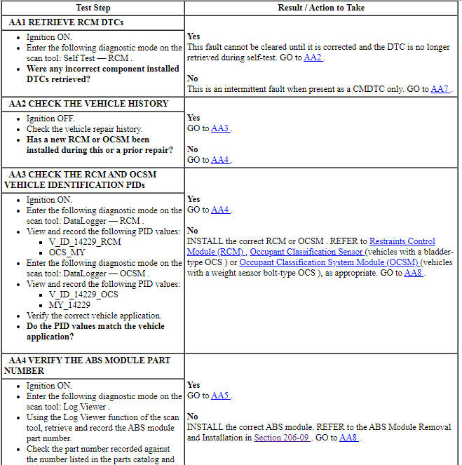
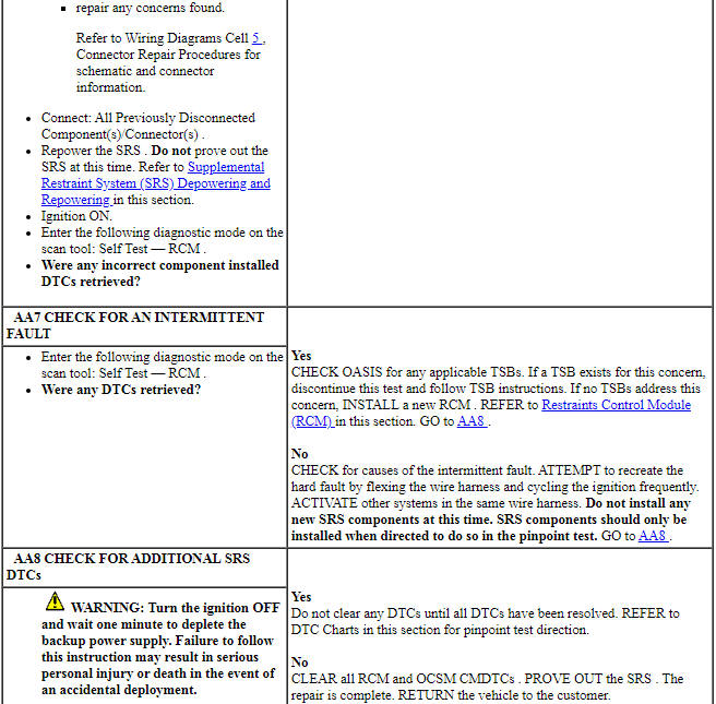
Pinpoint Test AB: DTCs U0028:08 and U0028:88
Diagnostic Overview
Diagnostics in this manual assume a certain skill level and knowledge of Ford-specific diagnostic practices. Refer to Diagnostic Methods in Section 100-00 for information about these practices.
Refer to Wiring Diagrams Cell 42, Vehicle Dynamic Systems for schematic and connector information.
Normal Operation and Fault Conditions
The RCM supplies the stability/traction control system with the yaw rate, roll rate, lateral and longitudinal accelerometer over a dedicated CAN bus. If the RCM detects a fault with communications with the ABS module or dedicated CAN bus circuits, it sets DTC U0028:08 or U0028:88.
The RCM does not request the IPC module to illuminate the air bag warning indicator if either DTC U0028:08 or U0028:88 is set.
- DTC U0028:08 (Vehicle Communication Bus A: Bus Signal / Message Failures) - A fault is indicted when the RCM does not receive messages from the ABS module on the dedicated CAN bus for 5 seconds. An open dedicated CAN circuit, incorrectly installed ABS module or loss of power and/or ground to the ABS module can set this DTC.
- DTC U0028:88 (Vehicle Communication Bus A: Bus Off) - A fault is indicted when the RCM detects the dedicated CAN circuits are shorted to ground, shorted to voltage or shorted to each other.
-
Visual Inspection and Diagnostic Pre-checks
- Inspect for damaged wiring harness(es).
- Inspect for a loose or damaged ABS module connector.
-
Possible Sources
- Wiring, terminals or connectors
- RCM
- ABS module
PINPOINT TEST AB: DTCs U0028:08 AND U0028:88
WARNING: Do not handle, move or change the original horizontal mounting position of the restraints control module (RCM) while the RCM is connected and the ignition switch is ON. Failure to follow this instruction may result in the accidental deployment of the Safety Canopy and cause serious personal injury or death.
WARNING: Never probe the electrical connectors on airbag, Safety Canopy or side air curtain assemblies. Failure to follow this instruction may result in the accidental deployment of these assemblies, which increases the risk of serious personal injury or death.
WARNING: Never disassemble or tamper with seat belt deployable components, including pretensioners, load limiters and inflators. Never back probe deployable device electrical connectors. Tampering or back probing may cause an accidental deployment and result in personal injury or death.
NOTICE: Use the correct probe adapter(s) from the Flex Probe Kit when taking measurements. Failure to use the correct probe adapter(s) may damage the connector.
NOTE: Most faults are due to connector and/or wiring concerns. Carry out a thorough inspection and verification before proceeding with the pinpoint test.
NOTE: Only disconnect or reconnect SRS components when instructed to do so within a pinpoint test step. Failure to follow this instruction may result in incorrect diagnosis of the SRS.
NOTE: Always make sure the correct SRS component is being installed. Parts released for other vehicles may not be compatible even if they appear physically similar. Check the part number listed in the parts catalog to make sure the correct component is being installed. If an incorrect SRS component is installed, DTCs may set.
NOTE: The SRS must be fully operational and free of faults before releasing the vehicle to the customer.
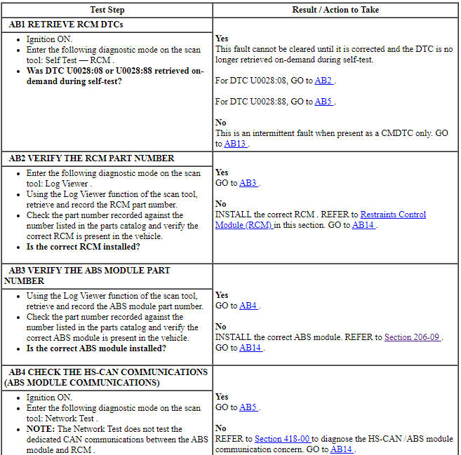
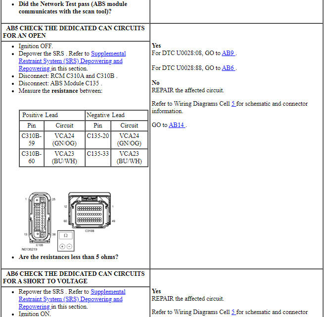
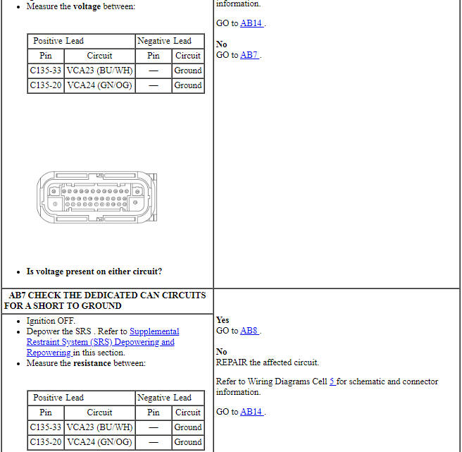
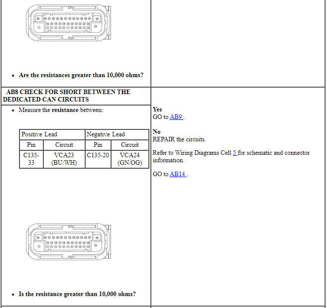
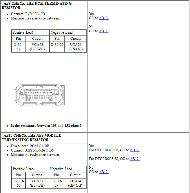
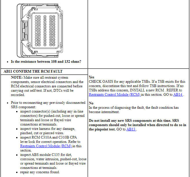
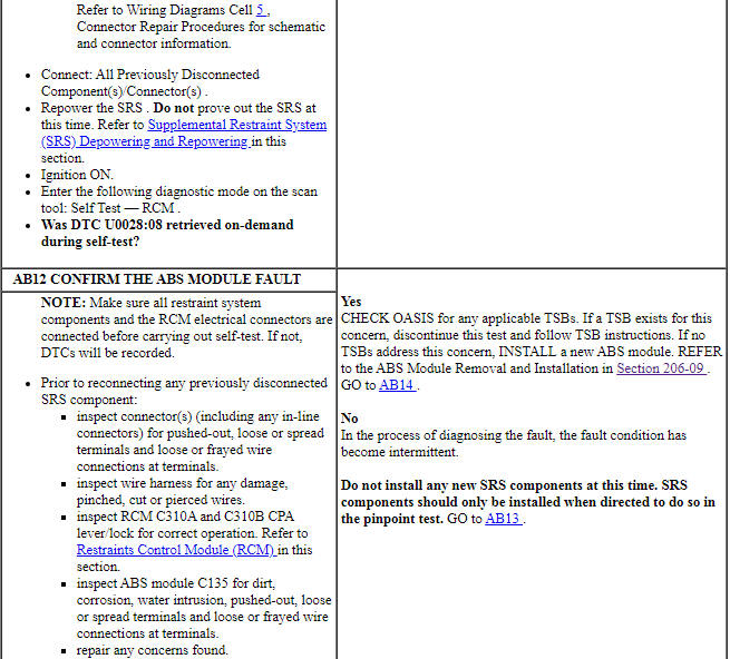
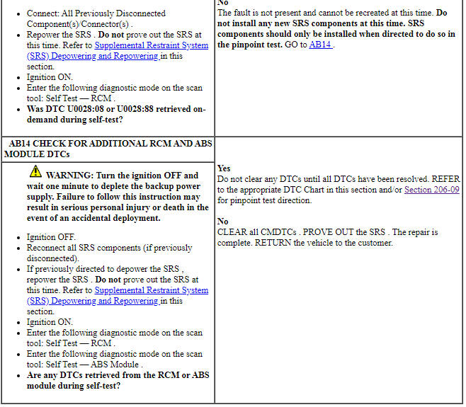
Pinpoint Test AC: DTC U0140:00
Diagnostic Overview
Diagnostics in this manual assume a certain skill level and knowledge of Ford-specific diagnostic practices. Refer to Diagnostic Methods in Section 100-00 for information about these practices.
Refer to Wiring Diagrams Cell 46, Supplemental Restraint System for schematic and connector information.
Normal Operation and Fault Conditions
The RCM uses information contained in messages from the BCM sent on the HS-CAN.
- DTC U0140:00 (Lost Communication with Body Control Module: No Sub Type Information) - This DTC sets if the RCM does not receive an expected message from the BCM.
-
Possible Sources
- Network traffic
- BCM
- RCM
PINPOINT TEST AC: DTC U0140:00
WARNING: Do not handle, move or change the original horizontal mounting position of the restraints control module (RCM) while the RCM is connected and the ignition switch is ON. Failure to follow this instruction may result in the accidental deployment of the Safety Canopy and cause serious personal injury or death.
NOTE: Most faults are due to connector and/or wiring concerns. Carry out a thorough inspection and verification before proceeding with the pinpoint test.
NOTE: SRS components should only be disconnected or reconnected when instructed to do so within a pinpoint test step. Failure to follow this instruction may result in incorrect diagnosis of the SRS.
NOTE: Always make sure the correct SRS component is being installed. Parts released for other vehicles may not be compatible even if they appear physically similar. Check the part number listed in the parts catalog to make sure the correct component is being installed. If an incorrect SRS component is installed, DTCs may set.
NOTE: The SRS must be fully operational and free of faults before releasing the vehicle to the customer.
Pinpoint Test AD: DTC U0154:00
Diagnostic Overview
Diagnostics in this manual assume a certain skill level and knowledge of Ford-specific diagnostic practices. Refer to Diagnostic Methods in Section 100-00 for information about these practices.
Refer to Wiring Diagrams Cell 46, Supplemental Restraint System for schematic and connector information.
Normal Operation and Fault Conditions
The RCM uses information contained in messages from the OCSM sent on the HS-CAN.
- DTC U0154:00 (Lost Communication with Restraints Occupant Classification System Module: No Sub Type Information) - This DTC sets if the RCM does not receive an expected message from the OCSM for 6 seconds.
-
Possible Sources
- Network traffic
- OCSM
- RCM
PINPOINT TEST AD: DTC U0154:00
WARNING: Do not handle, move or change the original horizontal mounting position of the restraints control module (RCM) while the RCM is connected and the ignition switch is ON. Failure to follow this instruction may result in the accidental deployment of the Safety Canopy and cause serious personal injury or death.
WARNING: Never probe the electrical connectors on airbag, Safety Canopy or side air curtain assemblies. Failure to follow this instruction may result in the accidental deployment of these assemblies, which increases the risk of serious personal injury or death.
WARNING: Never disassemble or tamper with seat belt deployable components, including pretensioners, load limiters and inflators. Never back probe deployable device electrical connectors. Tampering or back probing may cause an accidental deployment and result in personal injury or death.
NOTE: Most faults are due to connector and/or wiring concerns. Carry out a thorough inspection and verification before proceeding with the pinpoint test.
NOTE: SRS components should only be disconnected or reconnected when instructed to do so within a pinpoint test step. Failure to follow this instruction may result in incorrect diagnosis of the SRS.
NOTE: Always make sure the correct SRS component is being installed. Parts released for other vehicles may not be compatible even if they appear physically similar. Check the part number listed in the parts catalog to make sure the correct component is being installed. If an incorrect SRS component is installed, DTCs may set.
NOTE: The SRS must be fully operational and free of faults before releasing the vehicle to the customer.
Pinpoint Test AE: DTC U0155:00
Diagnostic Overview
Diagnostics in this manual assume a certain skill level and knowledge of Ford-specific diagnostic practices. Refer to Diagnostic Methods in Section 100-00 for information about these practices.
Refer to Wiring Diagrams Cell 46, Supplemental Restraint System for schematic and connector information.
Normal Operation and Fault Conditions
The RCM uses information contained in messages from the IPC sent on the HS-CAN.
- DTC U0155:00 (Lost Communication With Instrument Panel Cluster (IPC) Control Module: No Sub Type Information) - This DTC sets if the RCM does not receive an expected message from the IPC.
-
Possible Sources
- Network traffic
- IPC
- RCM
PINPOINT TEST AE: DTC U0155:00
WARNING: Do not handle, move or change the original horizontal mounting position of the restraints control module (RCM) while the RCM is connected and the ignition switch is ON. Failure to follow this instruction may result in the accidental deployment of the Safety Canopy and cause serious personal injury or death.
NOTE: Most faults are due to connector and/or wiring concerns. Carry out a thorough inspection and verification before proceeding with the pinpoint test.
NOTE: SRS components should only be disconnected or reconnected when instructed to do so within a pinpoint test step. Failure to follow this instruction may result in incorrect diagnosis of the SRS.
NOTE: Always make sure the correct SRS component is being installed. Parts released for other vehicles may not be compatible even if they appear physically similar. Check the part number listed in the parts catalog to make sure the correct component is being installed. If an incorrect SRS component is installed, DTCs may set.
NOTE: The SRS must be fully operational and free of faults before releasing the vehicle to the customer.
Pinpoint Test AF: DTC U0253:00
Diagnostic Overview
Diagnostics in this manual assume a certain skill level and knowledge of Ford-specific diagnostic practices. Refer to Diagnostic Methods in Section 100-00 for information about these practices.
Refer to Wiring Diagrams Cell 46, Supplemental Restraint System for schematic and connector information.
Normal Operation and Fault Conditions
The RCM uses information contained in messages from the APIM sent on the HS-CAN.
- DTC U0253:00 (Lost Communication With Accessory Protocol Interface Module: No Sub Type Information) - This DTC sets if the RCM does not receive an expected message from the APIM for 6 seconds.
-
Possible Sources
- Network traffic
- APIM
- RCM
PINPOINT TEST AF: DTC U0253:00
WARNING: Do not handle, move or change the original horizontal mounting position of the restraints control module (RCM) while the RCM is connected and the ignition switch is ON. Failure to follow this instruction may result in the accidental deployment of the Safety Canopy and cause serious personal injury or death.
NOTE: Most faults are due to connector and/or wiring concerns. Carry out a thorough inspection and verification before proceeding with the pinpoint test.
NOTE: SRS components should only be disconnected or reconnected when instructed to do so within a pinpoint test step. Failure to follow this instruction may result in incorrect diagnosis of the SRS.
NOTE: Always make sure the correct SRS component is being installed. Parts released for other vehicles may not be compatible even if they appear physically similar. Check the part number listed in the parts catalog to make sure the correct component is being installed. If an incorrect SRS component is installed, DTCs may set.
NOTE: The SRS must be fully operational and free of faults before releasing the vehicle to the customer.
Pinpoint Test AG: DTCs U3003:16 and U3003:17
Diagnostic Overview
Diagnostics in this manual assume a certain skill level and knowledge of Ford-specific diagnostic practices. Refer to Diagnostic Methods in Section 100-00 for information about these practices.
Refer to Wiring Diagrams Cell 46, Supplemental Restraint System for schematic and connector information.
NOTE: DTC U3003:16 and U3003:17 can be set if the vehicle has been recently jump started, the battery has been recently charged or the battery has been discharged. The battery may become discharged due to excessive load(s) on the charging system from aftermarket accessories or if the battery has been left unattended with the accessories on.
Normal Operation and Fault Conditions - RCM
The RCM continuously monitors the input voltage for correct operation. If the RCM detects input voltage below 9.5 volts when another RCM fault is present, or if the RCM detects voltage below 8.0 volts, regardless of fault status, it stores DTC U3003:16 in memory. If the RCM detects input voltage above 16.0 volts when another RCM fault is present, or if the RCM detects voltage above 18.0 volts, regardless of fault status, it stores DTC U3003:17 in memory. If the RCM sets DTC U3003:16 or U3003:17, it sends a message to the IPC to illuminate the air bag warning indicator.
Normal Operation and Fault Conditions - OCSM - Weight Sensor Bolt System
The OCSM continuously monitors the input voltage for correct operation. If the OCSM detects input voltage below 9.6 volts when another OCS fault is present, or if the OCSM detects voltage below 7.6 volts, regardless of fault status, it stores DTC U3003:16 in memory. If the OCSM detects input voltage above 16.5 volts when another OCS fault is present, or if the OCSM detects voltage above 18.5 volts, it stores DTC U3003:17 in memory. If the OCSM sets DTC U3003:16 or U3003:17, it sends a fault message to the RCM. The RCM then sends a message to the IPC to illuminate the air bag warning indicator.
Normal Operation and Fault Conditions - OCSM - Bladder System
The OCSM continuously monitors the input voltage for correct operation. If the OCSM detects input voltage below 8 volts, it stores DTC U3003:16 in memory. If the OCSM detects input voltage above 18 volts, it stores DTC U3003:17 in memory. If the OCSM sets DTC U3003:16 or U3003:17, it sends a fault message to the RCM. The RCM then sends a message to the IPC to illuminate the air bag warning indicator.
-
Visual Inspection and Diagnostic Pre-checks
- Inspect for damaged wiring harness(es).
- Inspect for loose or damaged connectors.
-
Possible Sources
- Wiring, terminals or connectors
- OCSM
- RCM
PINPOINT TEST AG: DTCs U3003:16 AND U3003:17
WARNING: Always tighten the fasteners of the restraints control module (RCM) and impact sensor (if equipped) to the specified torque. Failure to do so may result in incorrect restraint system operation, which increases the risk of personal injury or death in a crash.
NOTICE: Use the correct probe adapter(s) from the Flex Probe Kit when taking measurements. Failure to use the correct probe adapter(s) may damage the connector.
NOTE: Most faults are due to connector and/or wiring concerns. Carry out a thorough inspection and verification before proceeding with the pinpoint test.
NOTE: Only disconnect or reconnect SRS components when instructed to do so within a pinpoint test step. Failure to follow this instruction may result in incorrect diagnosis of the SRS.
NOTE: Always make sure the correct SRS component is being installed. Parts released for other vehicles may not be compatible even if they appear physically similar. Check the part number listed in the parts catalog to make sure the correct component is being installed. If an incorrect SRS component is installed, DTCs may set.
NOTE: The SRS must be fully operational and free of faults before releasing the vehicle to the customer.
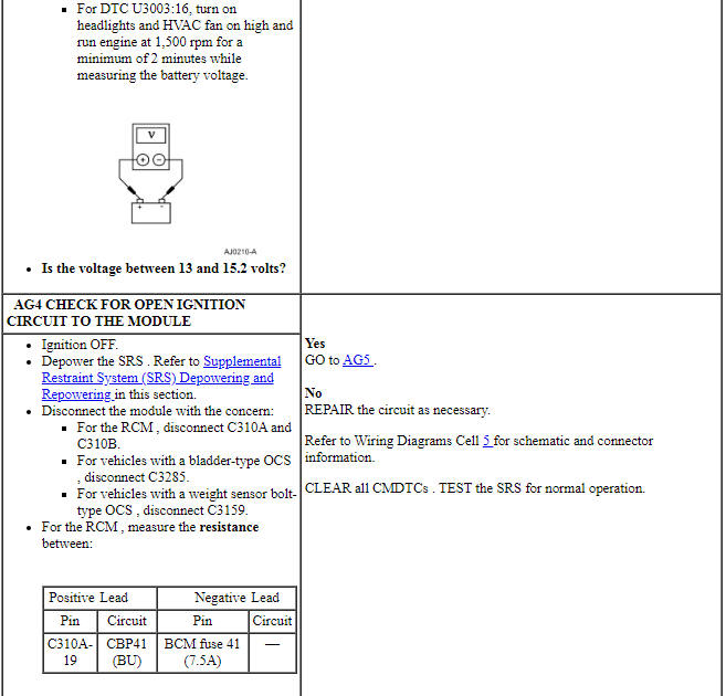
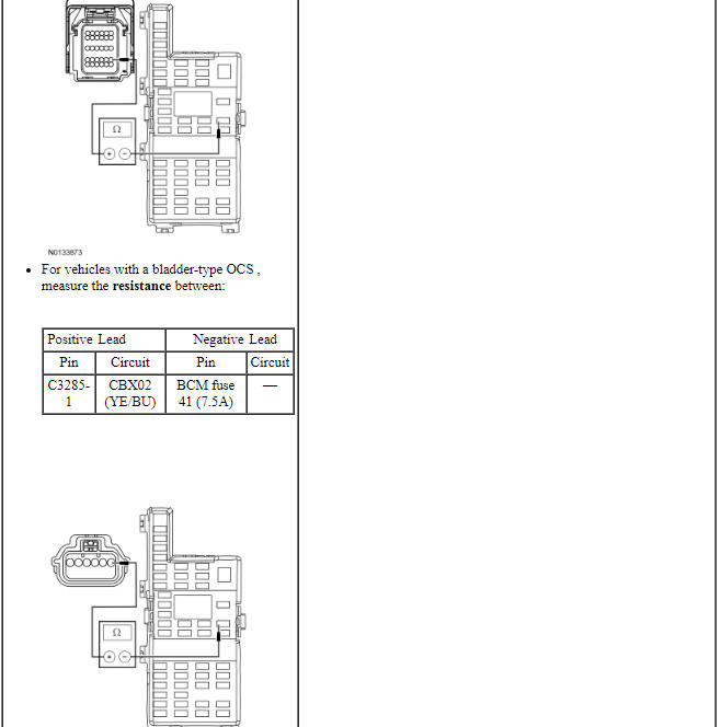
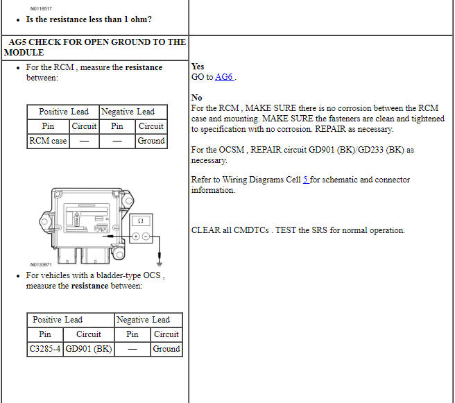
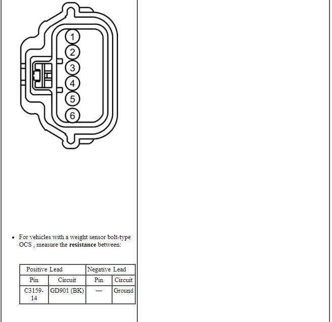
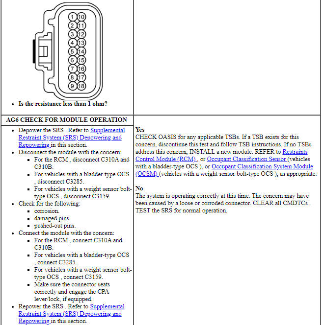

Pinpoint Test AH: DTCs B0061:11, B0061:12, B0061:13, B0061:1C and B0061:49
Diagnostic Overview
Diagnostics in this manual assume a certain skill level and knowledge of Ford-specific diagnostic practices. Refer to Diagnostic Methods in Section 100-00 for information about these practices.
Refer to Wiring Diagrams Cell 46, Supplemental Restraint System for schematic and connector information.
Normal Operation and Fault Conditions
The BTS operates in conjunction with the OCS. The OCS interprets a variable voltage signal provided by the BTS to identify the possible presence of a child safety seat in the front passenger seat. The voltage output of the BTS is proportional to the amount of tension applied to the sensor by the belt: no belt tension causes a low voltage (approximately 0.95 volt) to be output, and high belt tension causes a high voltage (approximately 3.8 volts) to be returned to the OCSM.
The OCSM monitors the BTS and related circuits for the following faults:
- Resistance out of range
- Unexpected voltage
- Short to ground
- Faulted BTS (part of front passenger safety belt buckle)
If a fault is detected, the OCSM stores DTC B0061:11, B0061:12, B0061:13, B0061:1C or B0061:49 in memory and sends a message to the RCM over the HS-CAN indicating that an OCS fault is present. Upon receipt of this message, the RCM sets DTC B00A0:68 and sends a message over the HS-CAN to the IPC to illuminate the air bag warning indicator.
-
Visual Inspection and Diagnostic Pre-checks
- Inspect for a damaged passenger safety belt buckle.
- Inspect for a damaged passenger seat cushion wiring harness.
- Inspect for a loose or damaged OCSM or BTS connector.
- Inspect for a damaged OCSM.
-
Possible Sources
- Wiring, terminals or connectors
- BTS (part of RH front passenger safety belt buckle)
- OCSM
PINPOINT TEST AH: DTCs B0061:11, B0061:12, B0061:13, B0061:1C and B0061:49
WARNING: Never disassemble or tamper with seat belt deployable components, including pretensioners, load limiters and inflators. Never back probe deployable device electrical connectors. Tampering or back probing may cause an accidental deployment and result in personal injury or death.
WARNING: Never probe the electrical connectors on airbag, Safety Canopy or side air curtain assemblies. Failure to follow this instruction may result in the accidental deployment of these assemblies, which increases the risk of serious personal injury or death.
NOTE: Most faults are due to connector and/or wiring concerns. Carry out a thorough inspection and verification before proceeding with the pinpoint test.
NOTE: Only disconnect or reconnect SRS components when instructed to do so within a pinpoint test step. Failure to follow this instruction may result in incorrect diagnosis of the SRS.
NOTE: Always make sure the correct SRS component is being installed. Parts released for other vehicles may not be compatible even if they appear physically similar. Check the part number listed in the parts catalog to make sure the correct component is being installed. If an incorrect SRS component is installed, DTCs may set.
NOTE: The SRS must be fully operational and free of faults before releasing the vehicle to the customer.
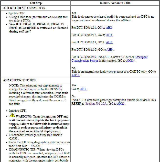
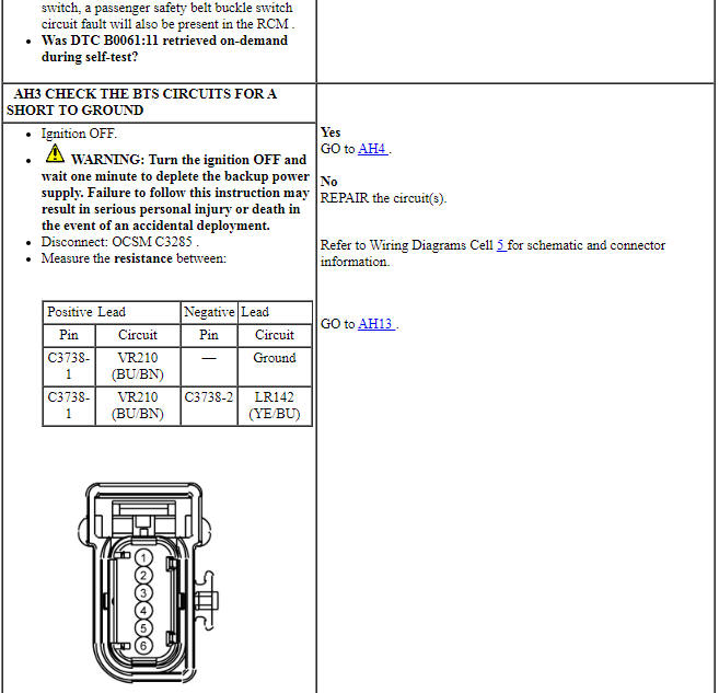
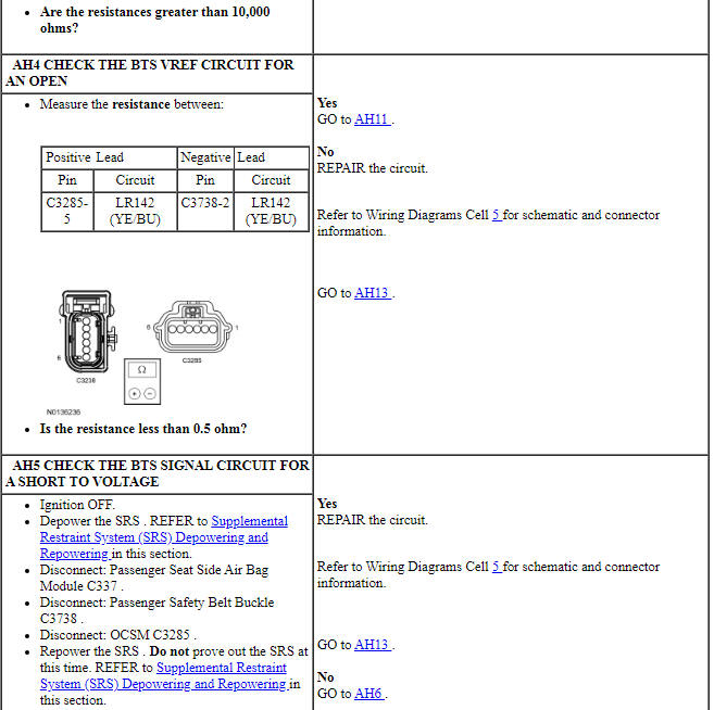
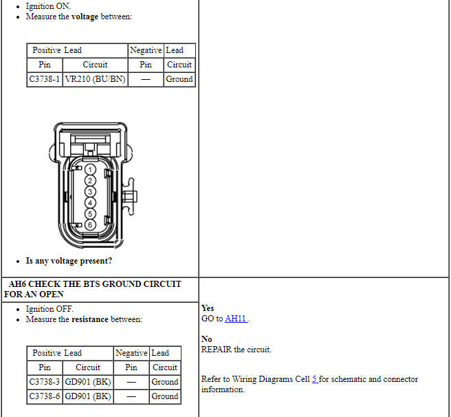
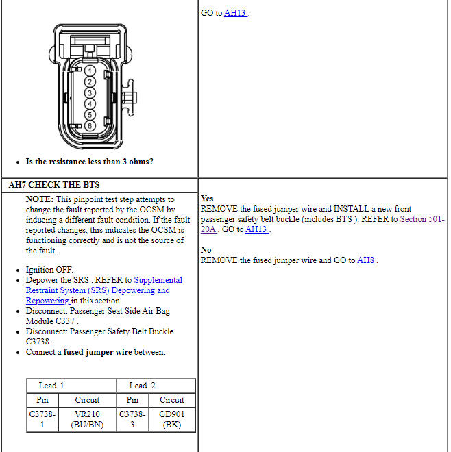
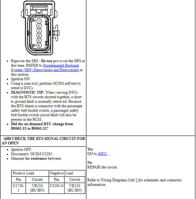
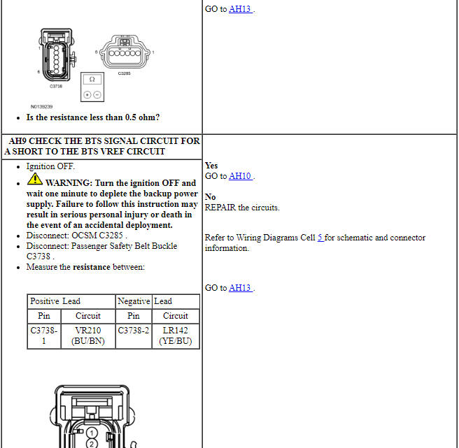
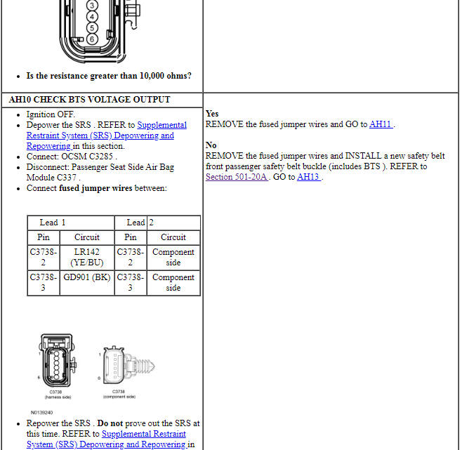
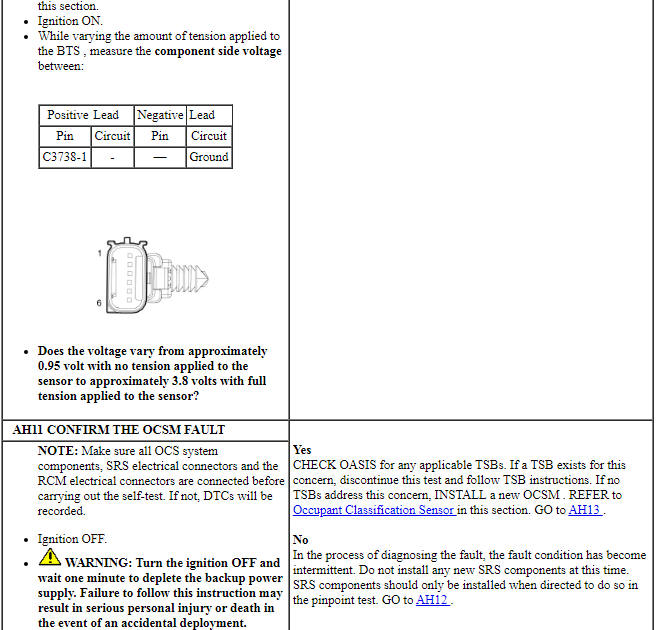
Pinpoint Test AI: DTCs B00C2:11 and B00C2:12
Diagnostic Overview
Diagnostics in this manual assume a certain skill level and knowledge of Ford-specific diagnostic practices. Refer to Diagnostic Methods in Section 100-00 for information about these practices.
Refer to Wiring Diagrams Cell 46, Supplemental Restraint System for schematic and connector information.
Normal Operation and Fault Conditions
The BTS operates in conjunction with the OCS. The OCSM provides a reference voltage to the BTS, which changes as it passes through the sensor, based on how much tension is applied to the safety belt and BTS.
The OCSM monitors the BTS reference voltage circuit for the following faults:
- Short to voltage
- Short to ground
If a fault is detected, the OCSM stores DTC B00C2:11 or B00C2:12 in memory and sends a message to the RCM over the HS-CAN indicating that an OCS fault is present. Upon receipt of this message, the RCM sets DTC B00A0:68 and sends a message over the HS-CAN to the IPC to illuminate the air bag warning indicator.
- DTC B00C2:11 (Passenger Seat Occupant Classification Sensor "C": Circuit Short to Ground) - A fault is indicated when the OCSM senses a short to ground on the BTS reference voltage circuit.
- DTC B00C2:12 (Passenger Seat Occupant Classification Sensor "C": Circuit Short to Battery) - A fault is indicated when the OCSM senses a short to voltage on the BTS reference voltage circuit.
-
Visual Inspection and Diagnostic Pre-checks
- Inspect for a damaged passenger safety belt buckle.
- Inspect for a damaged passenger seat cushion wiring harness.
- Inspect for a loose or damaged OCSM or BTS connector.
- Inspect for a damaged OCSM.
-
Possible Sources
- Wiring, terminals or connectors
- BTS (part of RH front passenger safety belt buckle)
- OCSM
PINPOINT TEST AI: DTCs B00C2:11 AND B00C2:12
WARNING: Never probe the electrical connectors on airbag, Safety Canopy or side air curtain assemblies. Failure to follow this instruction may result in the accidental deployment of these assemblies, which increases the risk of serious personal injury or death.
WARNING: Never disassemble or tamper with seat belt deployable components, including pretensioners, load limiters and inflators. Never back probe deployable device electrical connectors. Tampering or back probing may cause an accidental deployment and result in personal injury or death.
NOTE: Most faults are due to connector and/or wiring concerns. Carry out a thorough inspection and verification before proceeding with the pinpoint test.
NOTE: Only disconnect or reconnect SRS components when instructed to do so within a pinpoint test step. Failure to follow this instruction may result in incorrect diagnosis of the SRS.
NOTE: Always make sure the correct SRS component is being installed. Parts released for other vehicles may not be compatible even if they appear physically similar. Check the part number listed in the parts catalog to make sure the correct component is being installed. If an incorrect SRS component is installed, DTCs may set.
NOTE: The SRS must be fully operational and free of faults before releasing the vehicle to the customer.
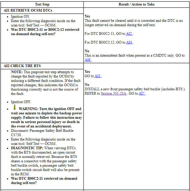
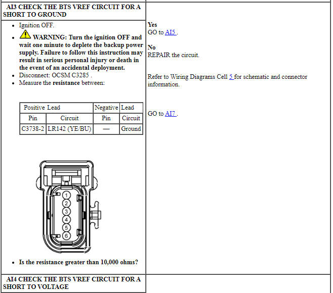
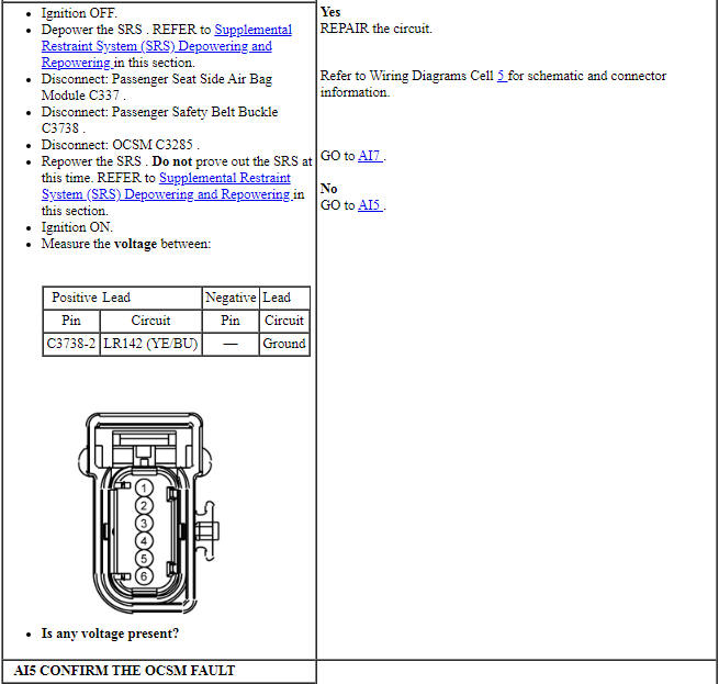
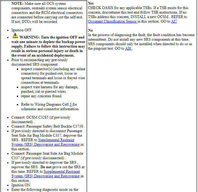
Pinpoint Test AJ: DTC U0100:00
Diagnostic Overview
Diagnostics in this manual assume a certain skill level and knowledge of Ford-specific diagnostic practices. Refer to Diagnostic Methods in Section 100-00 for information about these practices.
Refer to Wiring Diagrams Cell 46, Supplemental Restraint System for schematic and connector information.
Normal Operation and Fault Conditions
The OCSM and RCM both use information contained in messages from the PCM sent on the HS-CAN.
- DTC U0100:00 (Lost Communication with ECM/PCM "A": No Sub Type Information) - This DTC sets if the OCSM does not receive an expected message from the PCM.
- DTC U0100:00 (Lost Communication with ECM/PCM "A": No Sub Type Information) - This DTC sets if the RCM does not receive an expected message from the PCM.
-
Possible Sources
- Network traffic
- PCM
- RCM
- OCSM
PINPOINT TEST AJ: DTC U0100:00
WARNING: Do not handle, move or change the original horizontal mounting position of the restraints control module (RCM) while the RCM is connected and the ignition switch is ON. Failure to follow this instruction may result in the accidental deployment of the Safety Canopy and cause serious personal injury or death.
NOTE: Most faults are due to connector and/or wiring concerns. Carry out a thorough inspection and verification before proceeding with the pinpoint test.
NOTE: Only disconnect or reconnect SRS components when instructed to do so within a pinpoint test step. Failure to follow this instruction may result in incorrect diagnosis of the SRS.
NOTE: Always make sure the correct SRS component is being installed. Parts released for other vehicles may not be compatible even if they appear physically similar. Check the part number listed in the parts catalog to make sure the correct component is being installed. If an incorrect SRS component is installed, DTCs may set.
Pinpoint Test AK: DTC U0151:00
Diagnostic Overview
Diagnostics in this manual assume a certain skill level and knowledge of Ford-specific diagnostic practices. Refer to Diagnostic Methods in Section 100-00 for information about these practices.
Refer to Wiring Diagrams Cell 46, Supplemental Restraint System for schematic and connector information.
Normal Operation and Fault Conditions
The OCSM uses information contained in messages from the RCM sent on the HS-CAN.
- DTC U0151:00 (Lost Communication with Restraints Control Module: No Sub Type Information) - This DTC sets if the OCSM does not receive an expected message from the RCM.
-
Possible Sources
- Network traffic
- RCM
- OCSM
PINPOINT TEST AK: U0151:00
WARNING: Do not handle, move or change the original horizontal mounting position of the restraints control module (RCM) while the RCM is connected and the ignition switch is ON. Failure to follow this instruction may result in the accidental deployment of the Safety Canopy and cause serious personal injury or death.
WARNING: Never probe the electrical connectors on airbag, Safety Canopy or side air curtain assemblies. Failure to follow this instruction may result in the accidental deployment of these assemblies, which increases the risk of serious personal injury or death.
WARNING: Never disassemble or tamper with seat belt deployable components, including pretensioners, load limiters and inflators. Never back probe deployable device electrical connectors. Tampering or back probing may cause an accidental deployment and result in personal injury or death.
NOTE: Most faults are due to connector and/or wiring concerns. Carry out a thorough inspection and verification before proceeding with the pinpoint test.
NOTE: Only disconnect or reconnect SRS components when instructed to do so within a pinpoint test step. Failure to follow this instruction may result in incorrect diagnosis of the SRS.
NOTE: Always make sure the correct SRS component is being installed. Parts released for other vehicles may not be compatible even if they appear physically similar. Check the part number listed in the parts catalog to make sure the correct component is being installed. If an incorrect SRS component is installed, DTCs may set.
Pinpoint Test AL: DTCs B0061:11, B0061:12, B0061:13 and B0061:1C
Diagnostic Overview
Diagnostics in this manual assume a certain skill level and knowledge of Ford-specific diagnostic practices. Refer to Diagnostic Methods in Section 100-00 for information about these practices.
Refer to Wiring Diagrams Cell 46, Supplemental Restraint System for schematic and connector information.
Normal Operation and Fault Conditions
The safety BTS operates in conjunction with the OCS. The OCS interprets a variable voltage signal provided by the BTS to identify the possible presence of a child safety seat in the front passenger seat. The voltage output of the BTS is proportional to the amount of tension applied to the sensor by the belt. No tension outputs a low voltage (approximately 0.95 volt), and high tension outputs a high voltage (approximately 3.8 volts), in relation to the reference voltage.
The OCSM monitors the BTS and its related circuitry for the following faults:
- Resistance out of range
- Unexpected voltage
- Short to ground
- Faulted BTS (part of RH front safety belt buckle)
If a fault is detected, the OCSM stores DTC B0061:11, B0061:12, B0061:13 or B0061:1C in memory and sends a message to the RCM, which stores DTC B00A0:09 or B00A0:68 in memory and sends a message to the IPC to illuminate the air bag warning indicator.
-
Visual Inspection and Diagnostic Pre-checks
- Inspect for a damaged passenger safety belt buckle.
- Inspect for a damaged passenger seat cushion wiring harness.
- Inspect for a loose or damaged OCSM or BTS connector.
- Inspect for a damaged OCSM.
-
Possible Sources
- Wiring, terminals or connectors
- BTS (part of RH front passenger safety belt buckle)
- OCSM
PINPOINT TEST AL: DTCs B0061:11, B0061:12, B0061:13 AND B0061:1C
WARNING: Do not handle, move or change the original horizontal mounting position of the restraints control module (RCM) while the RCM is connected and the ignition switch is ON. Failure to follow this instruction may result in the accidental deployment of the Safety Canopy and cause serious personal injury or death.
WARNING: Never probe the electrical connectors on airbag, Safety Canopy or side air curtain assemblies. Failure to follow this instruction may result in the accidental deployment of these assemblies, which increases the risk of serious personal injury or death.
WARNING: Never disassemble or tamper with seat belt deployable components, including pretensioners, load limiters and inflators. Never back probe deployable device electrical connectors. Tampering or back probing may cause an accidental deployment and result in personal injury or death.
NOTICE: Use the correct probe adapter(s) from the Flex Probe Kit when taking measurements. Failure to use the correct probe adapter(s) may damage the connector.
NOTE: Most faults are due to connector and/or wiring concerns. Carry out a thorough inspection and verification before proceeding with the pinpoint test.
NOTE: Only disconnect or reconnect SRS components when instructed to do so within a pinpoint test step. Failure to follow this instruction may result in incorrect diagnosis of the SRS.
NOTE: Always make sure the correct SRS component is being installed. Parts released for other vehicles may not be compatible even if they appear physically similar. Check the part number listed in the parts catalog to make sure the correct component is being installed. If an incorrect SRS component is installed, DTCs may set.
NOTE: The SRS must be fully operational and free of faults before releasing the vehicle to the customer.
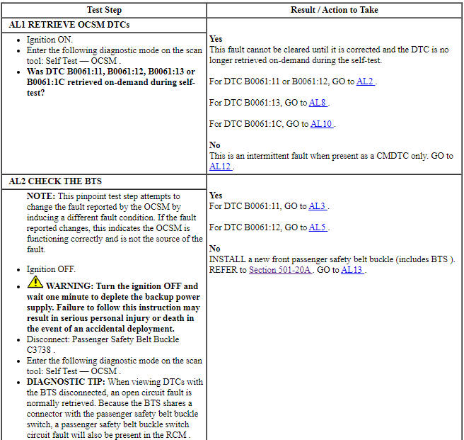
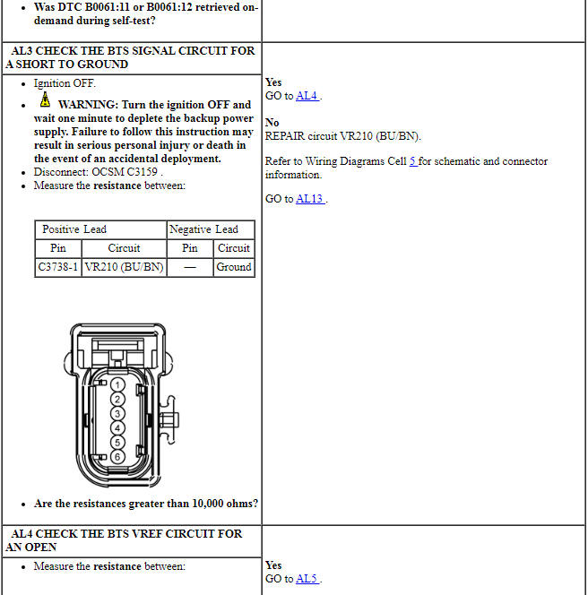
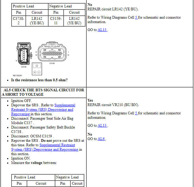
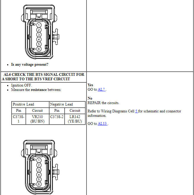
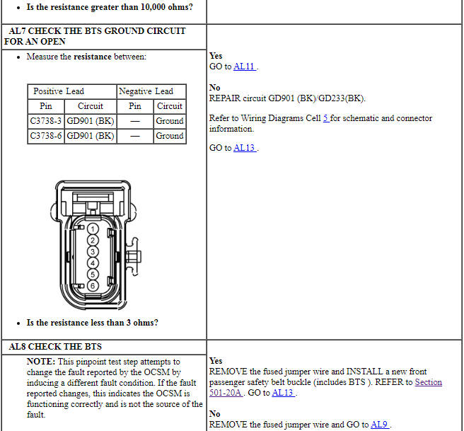
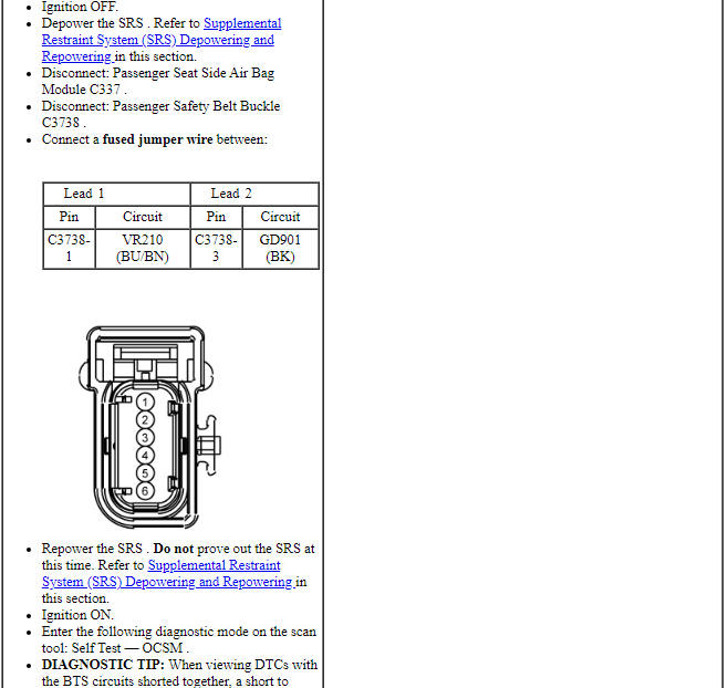
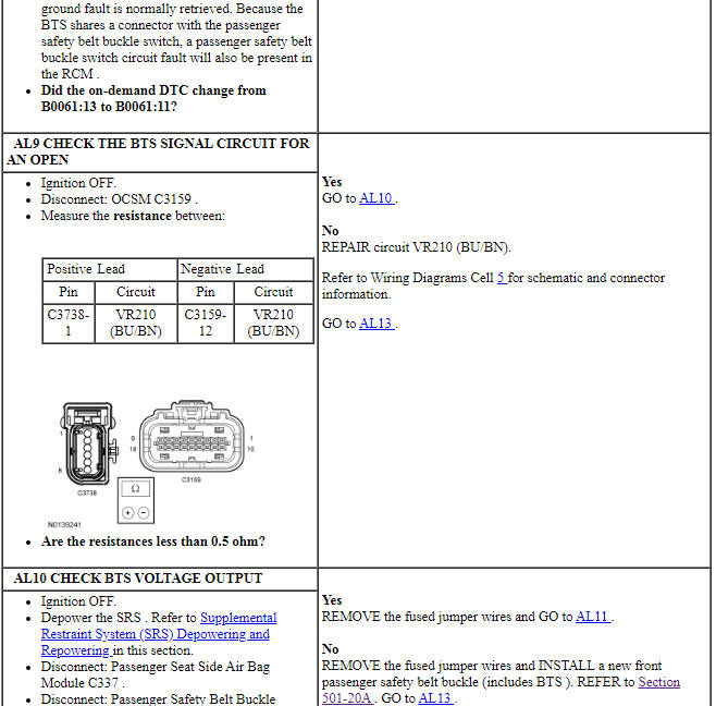
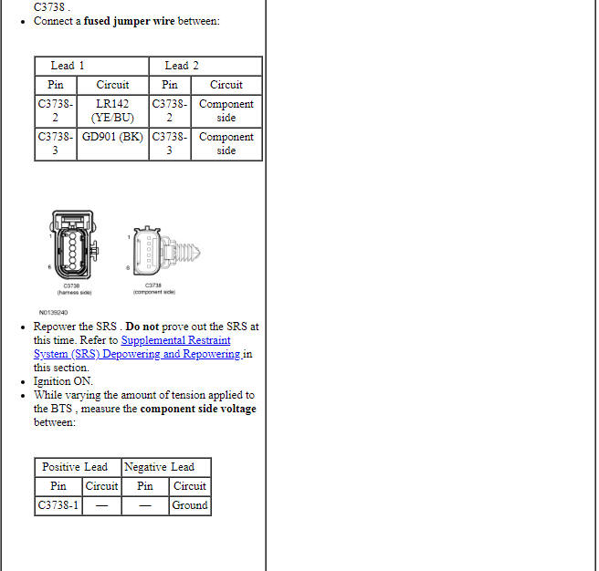
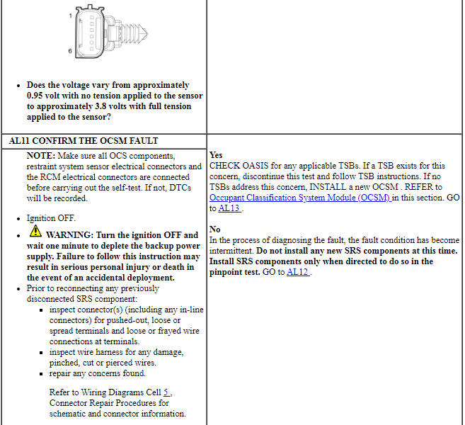
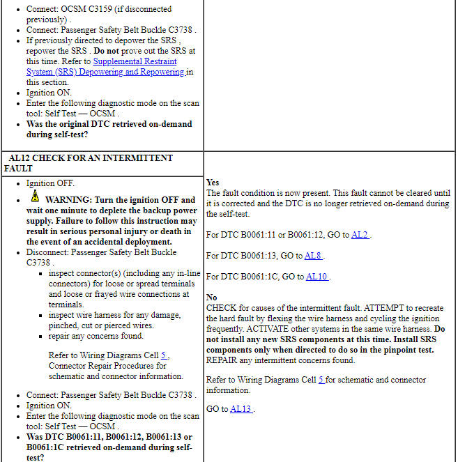
Pinpoint Test AM: DTCs B00A0:54, B00A0:76, B00C2:49 and B00C3:49
Diagnostic Overview
Diagnostics in this manual assume a certain skill level and knowledge of Ford-specific diagnostic practices. Refer to Diagnostic Methods in Section 100-00 for information about these practices.
Refer to Wiring Diagrams Cell 46, Supplemental Restraint System for schematic and connector information.
Normal Operation and Fault Conditions
The OCSM monitors each OCS weight sensor bolt for correct calibration/weight and identification. When the OCSM detects a fault from either of the 2 sensors or if an OCS component has been installed new, it stores a DTC in memory and sends a message to the RCM.
When the RCM receives a fault message from the OCS, it stores DTC B00A0:09 in memory and sends a message to the IPC to illuminate the air bag warning indicator.
-
Visual Inspection and Diagnostic Pre-checks
- Inspect for a damaged passenger seat cushion wiring harness.
- Inspect for a damaged seat track.
- Inspect for a damaged OCSM or OCSM connector.
- Inspect for damaged weight sensors or weight sensor connectors.
- Inspect the passenger seat cushion wiring harness routing.
-
Possible Sources
- Wiring, terminals or connectors
- Passenger seat track
PINPOINT TEST AM: DTCs B00A0:54, B00A0:76, B00C2:49 AND B00C3:49
WARNING: Never probe the electrical connectors on airbag, Safety Canopy or side air curtain assemblies. Failure to follow this instruction may result in the accidental deployment of these assemblies, which increases the risk of serious personal injury or death.
WARNING: Never disassemble or tamper with seat belt deployable components, including pretensioners, load limiters and inflators. Never back probe deployable device electrical connectors. Tampering or back probing may cause an accidental deployment and result in personal injury or death.
NOTICE: Use the correct probe adapter(s) from the Flex Probe Kit when taking measurements. Failure to use the correct probe adapter(s) may damage the connector.
NOTE: Most faults are due to connector and/or wiring concerns. Carry out a thorough inspection and verification before proceeding with the pinpoint test.
NOTE: Only disconnect or reconnect SRS components when instructed to do so within a pinpoint test step. Failure to follow this instruction may result in incorrect diagnosis of the SRS.
NOTE: Do not install any new OCS components until directed to do so. OCS components should only be installed when directed to do so in the pinpoint test.
NOTE: Always make sure the correct SRS component is being installed. Parts released for other vehicles may not be compatible even if they appear physically similar. Check the part number listed in the parts catalog to make sure the correct component is being installed. If an incorrect SRS component is installed, DTCs may set.
NOTE: The SRS must be fully operational and free of faults before releasing the vehicle to the customer.
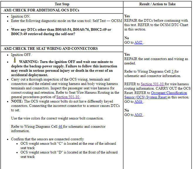
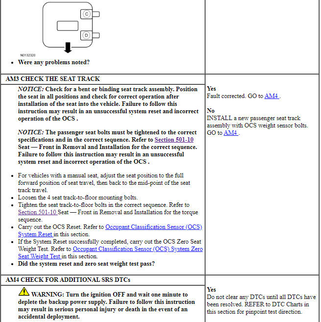
Pinpoint Test AN: DTC B00A0:97
Diagnostic Overview
Diagnostics in this manual assume a certain skill level and knowledge of Ford-specific diagnostic practices. Refer to Diagnostic Methods in Section 100-00 for information about these practices.
Refer to Wiring Diagrams Cell 46, Supplemental Restraint System for schematic and connector information.
Normal Operation and Fault Conditions
The OCSM monitors each OCS weight sensor bolt and circuitry for faults. If the OCSM detects an upward force (obstruction) on the passenger seat for 60 seconds, it stores DTC B00A0:97 in memory and sends a message to the RCM, which stores DTC B00A0:09 or B00A0:68 in memory and sends a message to the IPC to illuminate the air bag warning indicator.
- DTC B00A0:97 (Occupant Classification System: Component or System Operation Obstructed or Blocked) - This DTC sets if the OCSM detects a negative (upward) force on one or more OCS weight sensor bolt(s).
-
Visual Inspection and Diagnostic Pre-checks
- Inspect for a damaged seat track.
- Inspect the passenger seat cushion wiring harness routing.
- Inspect for foreign objects in the seat track.
-
Possible Sources
- Foreign object placed under or contacting the passenger seat
- OCSM
PINPOINT TEST AN: DTC B00A0:97
WARNING: Never probe the electrical connectors on airbag, Safety Canopy or side air curtain assemblies. Failure to follow this instruction may result in the accidental deployment of these assemblies, which increases the risk of serious personal injury or death.
WARNING: Never disassemble or tamper with seat belt deployable components, including pretensioners, load limiters and inflators. Never back probe deployable device electrical connectors. Tampering or back probing may cause an accidental deployment and result in personal injury or death.
NOTICE: Use the correct probe adapter(s) from the Flex Probe Kit when taking measurements. Failure to use the correct probe adapter(s) may damage the connector.
NOTE: Most faults are due to connector and/or wiring concerns. Carry out a thorough inspection and verification before proceeding with the pinpoint test.
NOTE: Only disconnect or reconnect SRS components when instructed to do so within a pinpoint test step. Failure to follow this instruction may result in incorrect diagnosis of the SRS.
NOTE: Always make sure the correct SRS component is being installed. Parts released for other vehicles may not be compatible even if they appear physically similar. Check the part number listed in the parts catalog to make sure the correct component is being installed. If an incorrect SRS component is installed, DTCs may set.
NOTE: The OCS weight sensor bolt(s) are 3 wire sensors and cannot be tested using a multi-meter.
NOTE: The SRS must be fully operational and free of faults before releasing the vehicle to the customer.
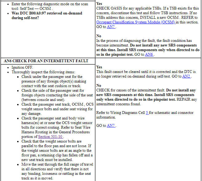
Pinpoint Test AO: DTCs B00C2:12, B00C2:13 and B00C2:1A
Diagnostic Overview
Diagnostics in this manual assume a certain skill level and knowledge of Ford-specific diagnostic practices. Refer to Diagnostic Methods in Section 100-00 for information about these practices.
Refer to Wiring Diagrams Cell 46, Supplemental Restraint System for schematic and connector information.
Normal Operation and Fault Conditions
The OCSM monitors the OCS weight sensor bolt "C" and circuitry for faults. If the OCSM detects a fault, it stores DTC B00C2:12, B00C2:13 or B00C2:1A in memory and sends a message to the RCM, which stores DTC B00A0:09 in memory and sends a message to the IPC to illuminate the air bag warning indicator.
- DTC B00C2:12 (Passenger Seat Occupant Classification Sensor "C": Circuit Short To Battery) - A fault is indicated when the OCSM measures voltage on the OCS weight sensor bolt "C" signal circuit above 4.85 volts. An open sensor return circuit also sets this DTC.
- DTC B00C2:13 (Passenger Seat Occupant Classification Sensor "C": Circuit Open) - A fault is indicated when the OCSM measures resistance above a calibrated threshold on the OCS weight sensor bolt "C" signal circuit.
- DTC B00C2:1A (Passenger Seat Occupant Classification Sensor "C": Circuit Resistance Below Threshold) - A fault is indicated when the OCSM measures resistance below a calibrated threshold on the OCS weight sensor bolt "C" signal circuit.
-
Visual Inspection and Diagnostic Pre-checks
- Inspect for a damaged passenger seat cushion wiring harness.
- Inspect for a damaged OCSM or OCSM connector.
- Inspect for damaged weight sensors or weight sensor connectors.
- Inspect the passenger seat cushion wiring harness routing.
-
Possible Sources
- Wiring, terminals or connectors
- OCS weight sensor bolt "C"
- OCSM
PINPOINT TEST AO: DTCs B00C2:12, B00C2:13 AND B00C2:1A
WARNING: Never probe the electrical connectors on airbag, Safety Canopy or side air curtain assemblies. Failure to follow this instruction may result in the accidental deployment of these assemblies, which increases the risk of serious personal injury or death.
WARNING: Never disassemble or tamper with seat belt deployable components, including pretensioners, load limiters and inflators. Never back probe deployable device electrical connectors. Tampering or back probing may cause an accidental deployment and result in personal injury or death.
NOTICE: Use the correct probe adapter(s) from the Flex Probe Kit when taking measurements. Failure to use the correct probe adapter(s) may damage the connector.
NOTE: Most faults are due to connector and/or wiring concerns. Carry out a thorough inspection and verification before proceeding with the pinpoint test.
NOTE: Only disconnect or reconnect SRS components when instructed to do so within a pinpoint test step. Failure to follow this instruction may result in incorrect diagnosis of the SRS.
NOTE: Always make sure the correct SRS component is being installed. Parts released for other vehicles may not be compatible even if they appear physically similar. Check the part number listed in the parts catalog to make sure the correct component is being installed. If an incorrect SRS component is installed, DTCs may set.
NOTE: The OCS weight sensor bolt(s) are 3 wire sensors and cannot be tested using a multi-meter.
NOTE: The SRS must be fully operational and free of faults before releasing the vehicle to the customer.
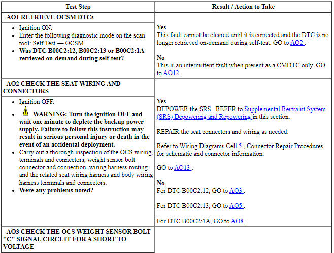
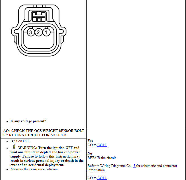
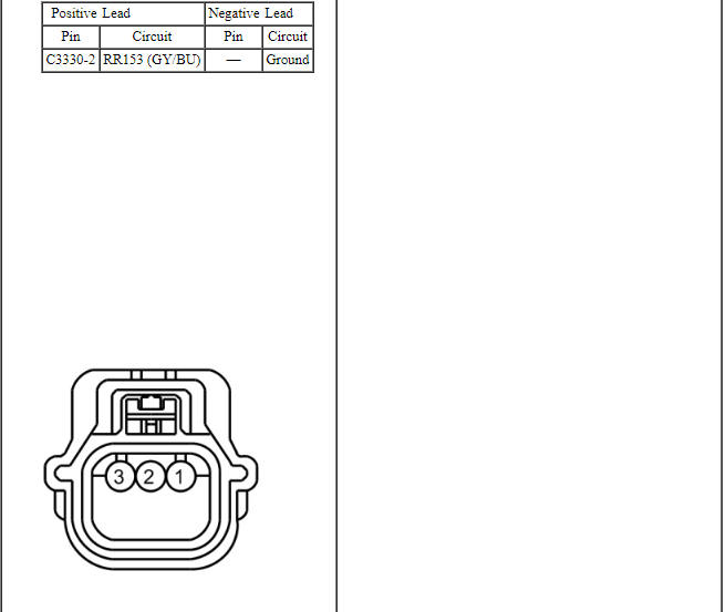
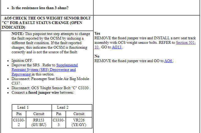
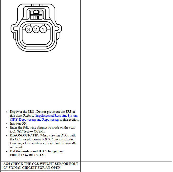
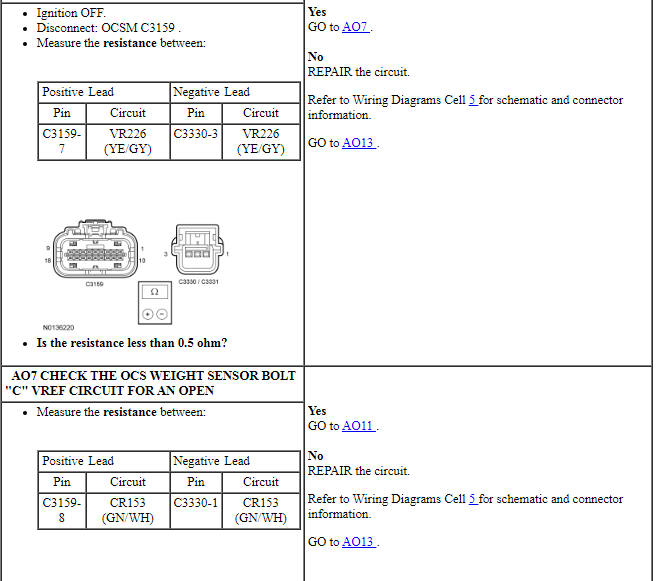
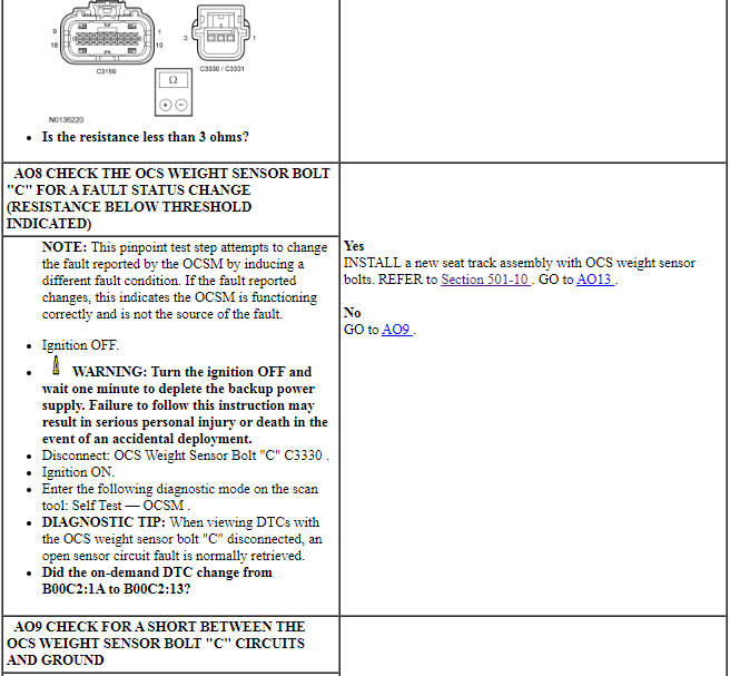
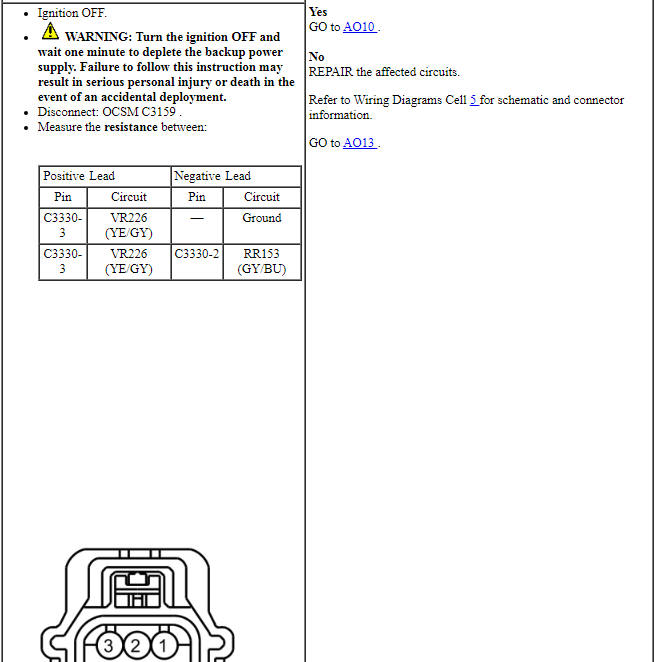
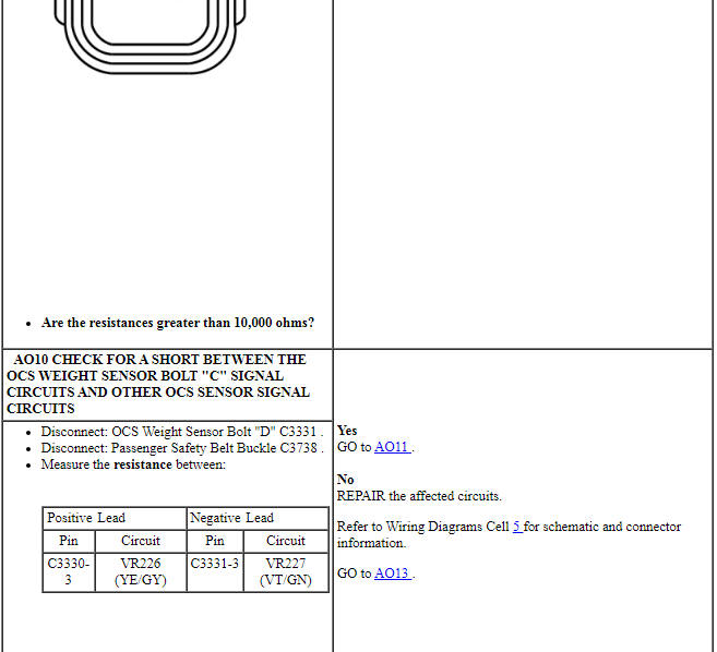
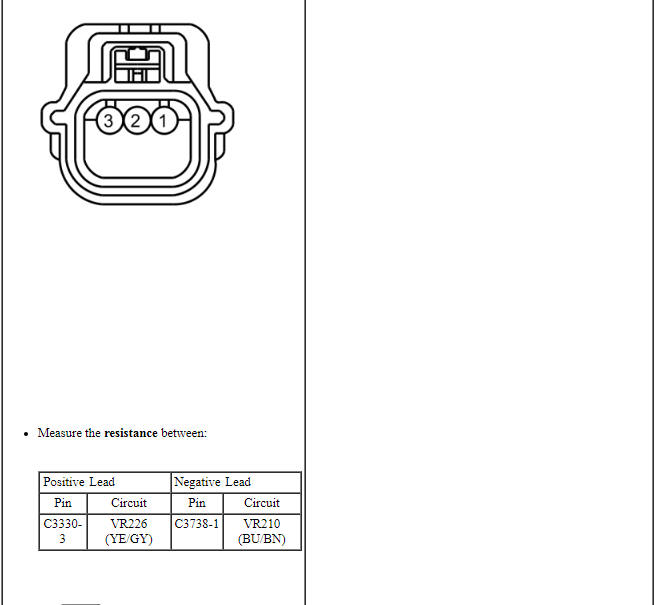
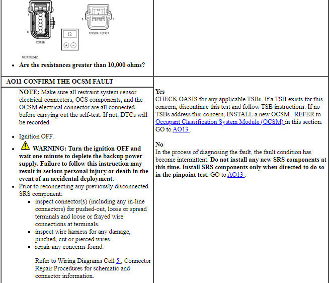
Pinpoint Test AP: DTCs B00C3:12, B00C3:13 and B00C3:1A
Diagnostic Overview
Diagnostics in this manual assume a certain skill level and knowledge of Ford-specific diagnostic practices. Refer to Diagnostic Methods in Section 100-00 for information about these practices.
Refer to Wiring Diagrams Cell 46, Supplemental Restraint System for schematic and connector information.
Normal Operation and Fault Conditions
The OCSM monitors OCS weight sensor bolt "D" and circuitry for faults. If the OCSM detects a fault, it stores DTC B00C3:12, B00C3:13 or B00C3:1A in memory and sends a message to the RCM.
The RCM stores DTC B00A0:09 in memory and sends a message to the IPC to illuminate the air bag warning indicator.
- DTC B00C3:12 (Passenger Seat Occupant Classification Sensor "D": Circuit Short To Battery) - A fault is indicated when the OCSM measures voltage on the OCS weight sensor bolt "D" signal circuit above 4.85 volts. An open sensor return circuit also sets this DTC.
- DTC B00C3:13 (Passenger Seat Occupant Classification Sensor "D": Circuit Open) - A fault is indicated when the OCSM measures resistance above a calibrated threshold on the OCS weight sensor bolt "D" signal circuit.
- DTC B00C3:1A (Passenger Seat Occupant Classification Sensor "D": Circuit Resistance Below Threshold) - A fault is indicated when the OCSM measures resistance below a calibrated threshold on the OCS weight sensor bolt "D" signal circuit.
-
Visual Inspection and Diagnostic Pre-checks
- Inspect for a damaged passenger seat cushion wiring harness.
- Inspect for a damaged OCSM or OCSM connector.
- Inspect for damaged weight sensors or weight sensor connectors.
- Inspect the passenger seat cushion wiring harness routing.
-
Possible Sources
- Wiring, terminals or connectors
- OCS weight sensor bolt "D"
- OCSM
PINPOINT TEST AP: DTCs B00C3:12, B00C3:13 AND B00C3:1A
WARNING: Never probe the electrical connectors on airbag, Safety Canopy or side air curtain assemblies. Failure to follow this instruction may result in the accidental deployment of these assemblies, which increases the risk of serious personal injury or death.
WARNING: Never disassemble or tamper with seat belt deployable components, including pretensioners, load limiters and inflators. Never back probe deployable device electrical connectors. Tampering or back probing may cause an accidental deployment and result in personal injury or death.
NOTICE: Use the correct probe adapter(s) from the Flex Probe Kit when taking measurements. Failure to use the correct probe adapter(s) may damage the connector.
NOTE: Most faults are due to connector and/or wiring concerns. Carry out a thorough inspection and verification before proceeding with the pinpoint test.
NOTE: Only disconnect or reconnect SRS components when instructed to do so within a pinpoint test step. Failure to follow this instruction may result in incorrect diagnosis of the SRS.
NOTE: Always make sure the correct SRS component is being installed. Parts released for other vehicles may not be compatible even if they appear physically similar. Check the part number listed in the parts catalog to make sure the correct component is being installed. If an incorrect SRS component is installed, DTCs may set.
NOTE: The OCS weight sensor bolt(s) are 3 wire sensors and cannot be tested using a multi-meter.
NOTE: The SRS must be fully operational and free of faults before releasing the vehicle to the customer.
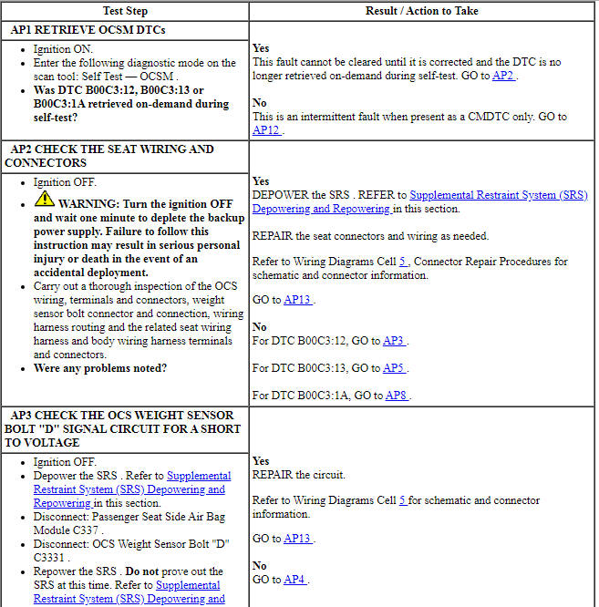
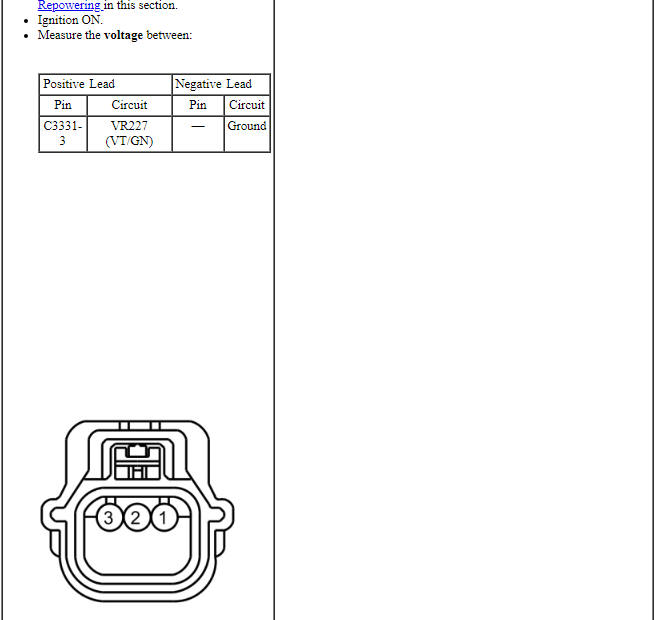
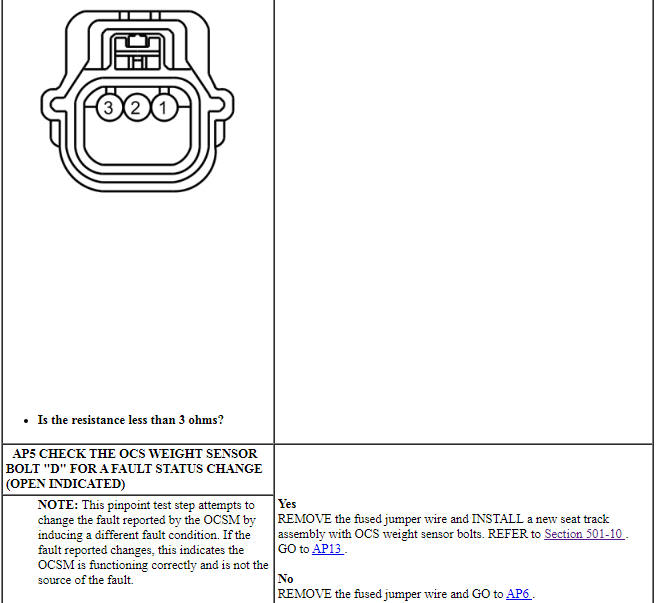
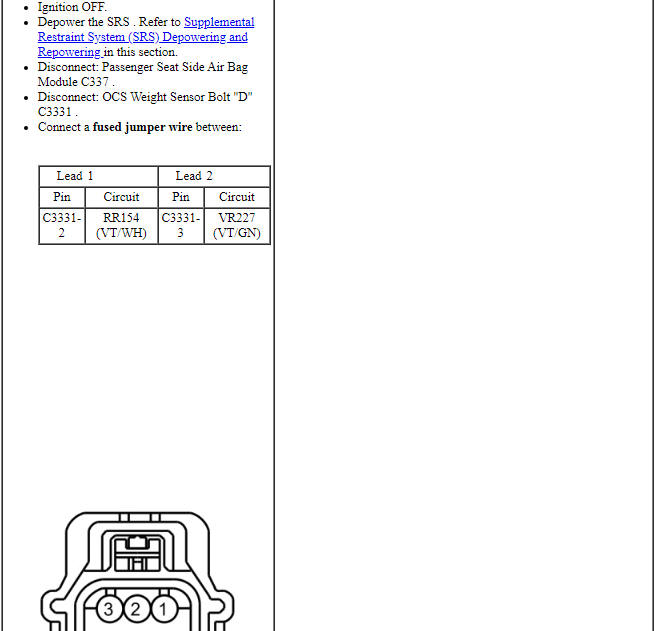
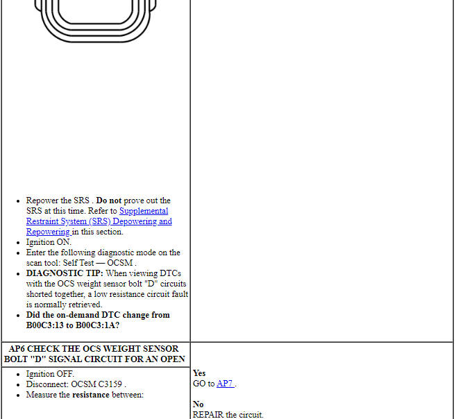
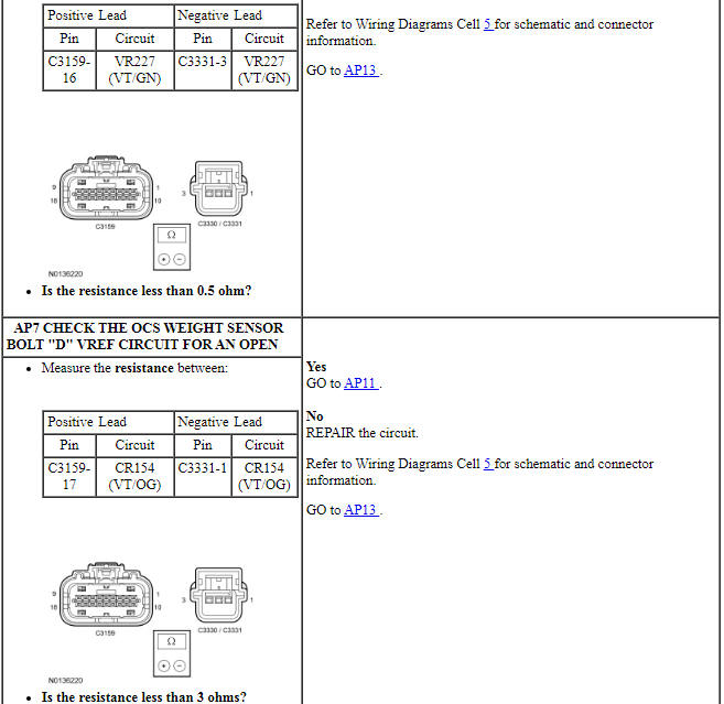
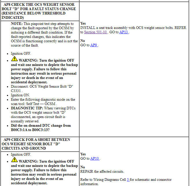
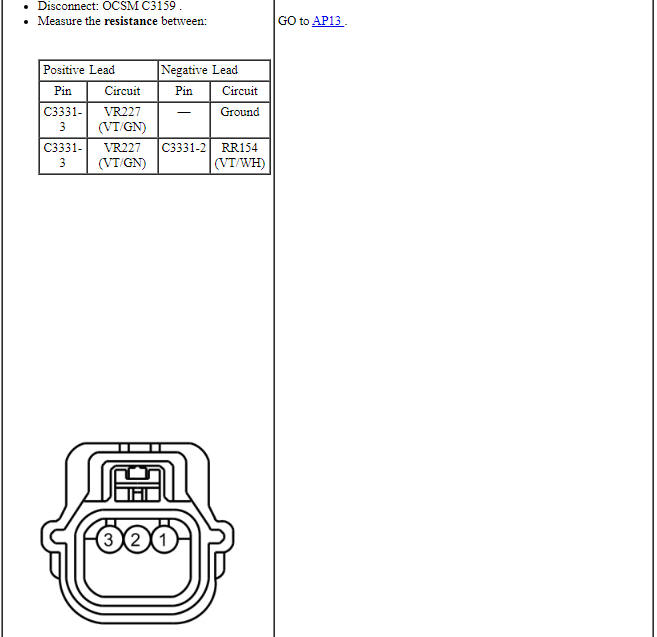
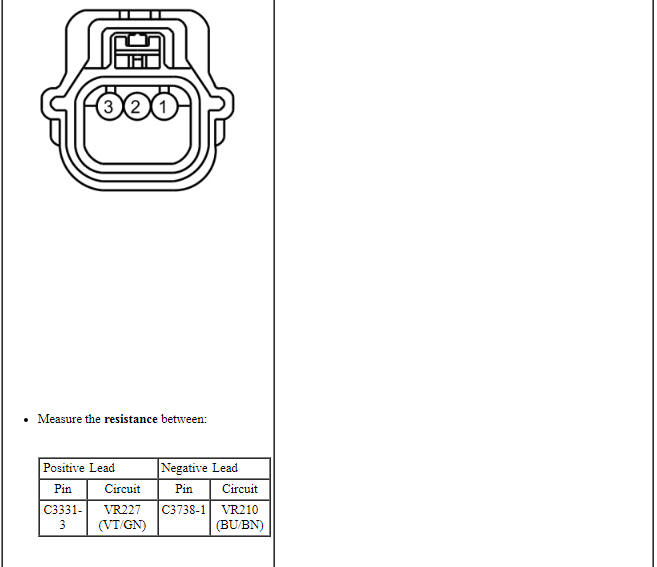
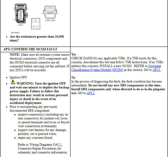
Pinpoint Test AQ: DTCs B1A59:01 and B1A59:11
Diagnostic Overview
Diagnostics in this manual assume a certain skill level and knowledge of Ford-specific diagnostic practices. Refer to Diagnostic Methods in Section 100-00 for information about these practices.
Refer to Wiring Diagrams Cell 46, Supplemental Restraint System for schematic and connector information.
Normal Operation and Fault Conditions
The OCSM monitors each OCS weight sensor bolt and circuitry for faults. If the OCSM detects a fault, it stores DTC B1A59:01 in memory and sends a message to the RCM.
The RCM stores DTC B00A0:09 in memory and sends a message to the IPC to illuminate the air bag warning indicator.
- DTC B1A59:01 (Sensor 5 Volt Supply: General Electrical Failure) - A fault is indicated when the OCSM senses a short between the BTS VREF circuit and one of the OCS weight sensor bolt VREF circuits. DTC U200E:1A may also set when this DTC is present. The OCSM only checks for this fault when the module is first powered on, and does not monitor for this fault after that initial "prove out".
- DTC B1A59:11 (Sensor 5 Volt Supply: Circuit Short To Ground) - A fault is indicated when the OCSM senses a short to ground on either of the OCS weight sensor bolt VREF circuits, or if the BTS VREF circuit is shorted to ground while an open circuit exists on the BTS VREF circuit ( BTS disconnected).
-
Visual Inspection and Diagnostic Pre-checks
- Inspect for a damaged passenger seat cushion wiring harness.
- Inspect for a damaged OCSM or OCSM connector.
- Inspect for damaged weight sensors or weight sensor connectors.
- Inspect the passenger seat cushion wiring harness routing.
-
Possible Sources
- Wiring, terminals or connectors
- Passenger seat track assembly
- OCSM
PINPOINT TEST AQ: DTCs B1A59:01 AND B1A59:11
WARNING: Never probe the electrical connectors on airbag, Safety Canopy or side air curtain assemblies. Failure to follow this instruction may result in the accidental deployment of these assemblies, which increases the risk of serious personal injury or death.
WARNING: Never disassemble or tamper with seat belt deployable components, including pretensioners, load limiters and inflators. Never back probe deployable device electrical connectors. Tampering or back probing may cause an accidental deployment and result in personal injury or death.
NOTICE: Use the correct probe adapter(s) from the Flex Probe Kit when making measurements. Failure to use the correct probe adapter(s) may damage the connector.
NOTE: Most faults are due to connector and/or wiring concerns. Carry out a thorough inspection and verification before proceeding with the pinpoint test.
NOTE: Only disconnect or reconnect SRS components when instructed to do so within a pinpoint test step. Failure to follow this instruction may result in incorrect diagnosis of the SRS.
NOTE: Do not install any new OCS components until directed to do so. OCS components should only be installed when directed to do so in the pinpoint test.
NOTE: Always make sure the correct SRS component is being installed. Parts released for other vehicles may not be compatible even if they appear physically similar. Check the part number listed in the parts catalog to make sure the correct component is being installed. If an incorrect SRS component is installed, DTCs may set.
NOTE: The SRS must be fully operational and free of faults before releasing the vehicle to the customer.
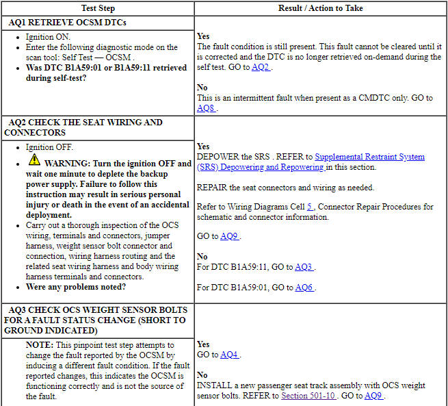
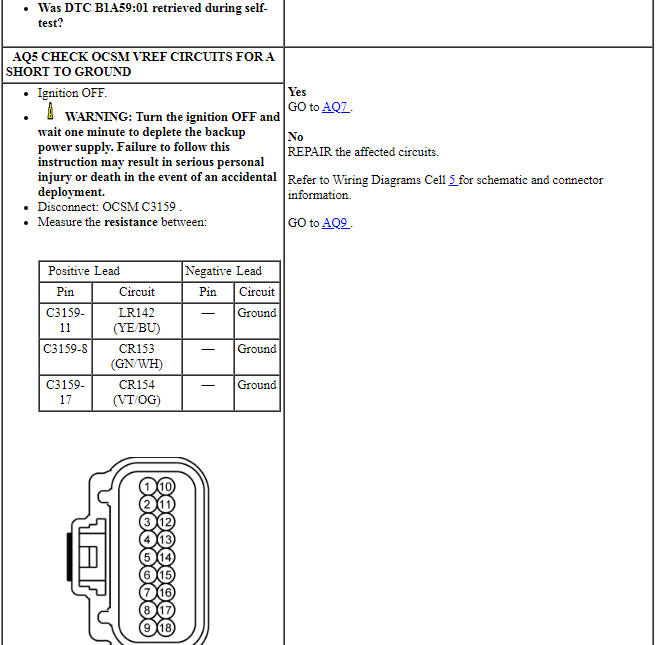
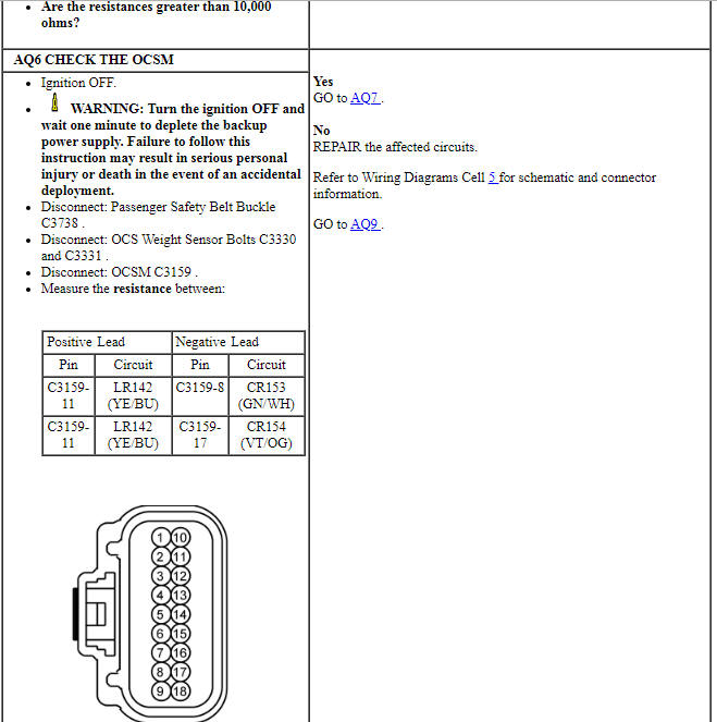
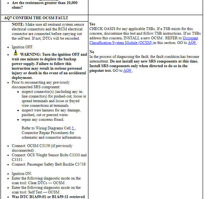
Pinpoint Test AR: DTC U0140:00
Diagnostic Overview
Diagnostics in this manual assume a certain skill level and knowledge of Ford-specific diagnostic practices. Refer to Diagnostic Methods in Section 100-00 for information about these practices.
Refer to Wiring Diagrams Cell 46, Supplemental Restraint System for schematic and connector information.
Normal Operation and Fault Conditions
The OCSM uses information contained in messages from the BCM sent on the HS-CAN.
- DTC U0140:00 (Lost Communication with Body Control Module: No Sub Type Information) - This DTC sets if the OCSM does not receive an expected message from the BCM.
-
Possible Sources
- Network traffic
- BCM
- OCSM
PINPOINT TEST AR: U0140:00
WARNING: Do not handle, move or change the original horizontal mounting position of the restraints control module (RCM) while the RCM is connected and the ignition switch is ON. Failure to follow this instruction may result in the accidental deployment of the Safety Canopy and cause serious personal injury or death.
WARNING: Never probe the electrical connectors on airbag, Safety Canopy or side air curtain assemblies. Failure to follow this instruction may result in the accidental deployment of these assemblies, which increases the risk of serious personal injury or death.
WARNING: Never disassemble or tamper with seat belt deployable components, including pretensioners, load limiters and inflators. Never back probe deployable device electrical connectors. Tampering or back probing may cause an accidental deployment and result in personal injury or death.
NOTE: Most faults are due to connector and/or wiring concerns. Carry out a thorough inspection and verification before proceeding with the pinpoint test.
NOTE: Only disconnect or reconnect SRS components when instructed to do so within a pinpoint test step. Failure to follow this instruction may result in incorrect diagnosis of the SRS.
NOTE: Always make sure the correct SRS component is being installed. Parts released for other vehicles may not be compatible even if they appear physically similar. Check the part number listed in the parts catalog to make sure the correct component is being installed. If an incorrect SRS component is installed, DTCs may set.
Pinpoint Test AS: DTC U200D:12
Diagnostic Overview
Diagnostics in this manual assume a certain skill level and knowledge of Ford-specific diagnostic practices. Refer to Diagnostic Methods in Section 100-00 for information about these practices.
Refer to Wiring Diagrams Cell 46, Supplemental Restraint System for schematic and connector information.
Normal Operation and Fault Conditions
The OCSM monitors each OCS weight sensor bolt and its circuitry for faults. If the OCSM detects unwanted voltage on any weight sensor VREF circuit, it stores DTC U200D:12 in memory and sends a message to the RCM.
The RCM stores DTC B00A0:09 in memory and sends a message to the IPC to illuminate the air bag warning indicator.
- DTC U200D:12 (Control Module Output Power A: Circuit Short to Battery) - If the OCSM detects voltage above 5 volts on any weight sensor VREF circuit, it sets this DTC.
-
Visual Inspection and Diagnostic Pre-checks
- Inspect for a damaged passenger seat cushion wiring harness.
- Inspect for a damaged OCSM or OCSM connector.
- Inspect for damaged weight sensors or weight sensor connectors.
- Inspect the passenger seat cushion wiring harness routing.
-
Possible Sources
- Wiring, terminals or connectors
- OCSM
PINPOINT TEST AS: DTC U200D:12
WARNING: Never probe the electrical connectors on airbag, Safety Canopy or side air curtain assemblies. Failure to follow this instruction may result in the accidental deployment of these assemblies, which increases the risk of serious personal injury or death.
WARNING: Never disassemble or tamper with seat belt deployable components, including pretensioners, load limiters and inflators. Never back probe deployable device electrical connectors. Tampering or back probing may cause an accidental deployment and result in personal injury or death.
NOTICE: Use the correct probe adapter(s) from the Flex Probe Kit when making measurements. Failure to use the correct probe adapter(s) may damage the connector.
NOTE: Most faults are due to connector and/or wiring concerns. Carry out a thorough inspection and verification before proceeding with the pinpoint test.
NOTE: Only disconnect or reconnect SRS components when instructed to do so within a pinpoint test step. Failure to follow this instruction may result in incorrect diagnosis of the SRS.
NOTE: Do not install any new OCS components until directed to do so. OCS components should only be installed when directed to do so in the pinpoint test.
NOTE: Always make sure the correct SRS component is being installed. Parts released for other vehicles may not be compatible even if they appear physically similar. Check the part number listed in the parts catalog to make sure the correct component is being installed. If an incorrect SRS component is installed, DTCs may set.
NOTE: The SRS must be fully operational and free of faults before releasing the vehicle to the customer.
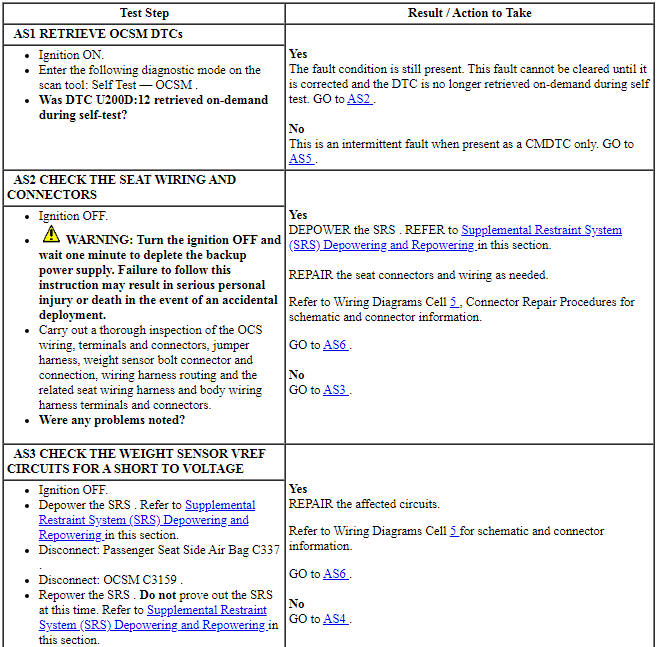
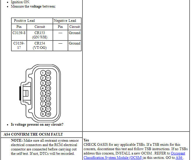
Pinpoint Test AT: DTCs U200E:11, U200E:12 and U200E:1A
Diagnostic Overview
Diagnostics in this manual assume a certain skill level and knowledge of Ford-specific diagnostic practices. Refer to Diagnostic Methods in Section 100-00 for information about these practices.
Refer to Wiring Diagrams Cell 46, Supplemental Restraint System for schematic and connector information.
Normal Operation and Fault Conditions
The OCSM monitors the BTS VREF circuit for faults. If the OCSM detects a fault, it stores DTC U200E:11, U200E:12 or U200E:1A in memory and sends a message to the RCM.
The RCM stores DTC B00A0:09 memory and sends a message to the IPC to illuminate the air bag warning indicator.
- DTC U200E:11 (Control Module Output Power B: Circuit Short to Ground) - A fault is indicated when the OCSM senses a short to a ground on the BTS VREF circuit. If an open circuit is present on the BTS signal circuit (such as if the BTS connector is disconnected) at the same time that the BTS VREF circuit is shorted to ground, only DTC B1A59:11 will be retrieved.
- DTC U200E:12 (Control Module Output Power B: Circuit Short to Battery) - A fault is indicated when the OCSM senses a short to voltage on the BTS VREF circuit.
- DTC U200E:1A (Control Module Output Power B: Circuit Resistance Below Threshold) - A fault is indicated when the OCSM senses that the BTS VREF circuit is shorted to the weight sensor VREF circuit(s). DTC B0061:12 and/or B1A59:01 may also set when this fault is present.
-
Visual Inspection and Diagnostic Pre-checks
- Inspect for a damaged passenger seat cushion wiring harness.
- Inspect for a damaged passenger safety belt buckle BTS connector.
- Inspect for a damaged OCSM or OCSM connector.
- Inspect for damaged weight sensors or weight sensor connectors.
- Inspect the passenger seat cushion wiring harness routing.
-
Possible Sources
- Wiring, terminals or connectors
- BTS (part of RH front safety belt buckle)
- OCSM
PINPOINT TEST AT: DTCs U200E:11, U200E:12 AND U200E:1A
WARNING: Never probe the electrical connectors on airbag, Safety Canopy or side air curtain assemblies. Failure to follow this instruction may result in the accidental deployment of these assemblies, which increases the risk of serious personal injury or death.
WARNING: Never disassemble or tamper with seat belt deployable components, including pretensioners, load limiters and inflators. Never back probe deployable device electrical connectors. Tampering or back probing may cause an accidental deployment and result in personal injury or death.
NOTICE: Use the correct probe adapter(s) from the Flex Probe Kit when making measurements. Failure to use the correct probe adapter(s) may damage the connector.
NOTE: Most faults are due to connector and/or wiring concerns. Carry out a thorough inspection and verification before proceeding with the pinpoint test.
NOTE: Only disconnect or reconnect SRS components when instructed to do so within a pinpoint test step. Failure to follow this instruction may result in incorrect diagnosis of the SRS.
NOTE: Do not install any new OCS components until directed to do so. OCS components should only be installed when directed to do so in the pinpoint test.
NOTE: Always make sure the correct SRS component is being installed. Parts released for other vehicles may not be compatible even if they appear physically similar. Check the part number listed in the parts catalog to make sure the correct component is being installed. If an incorrect SRS component is installed, DTCs may set.
NOTE: The SRS must be fully operational and free of faults before releasing the vehicle to the customer.
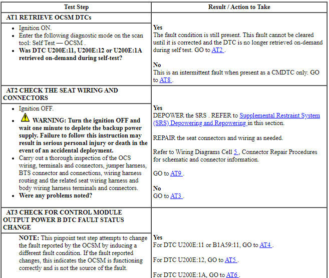
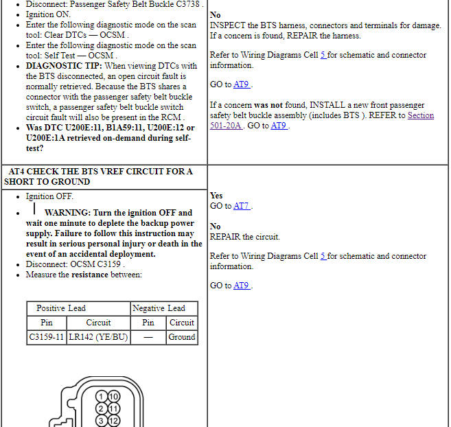
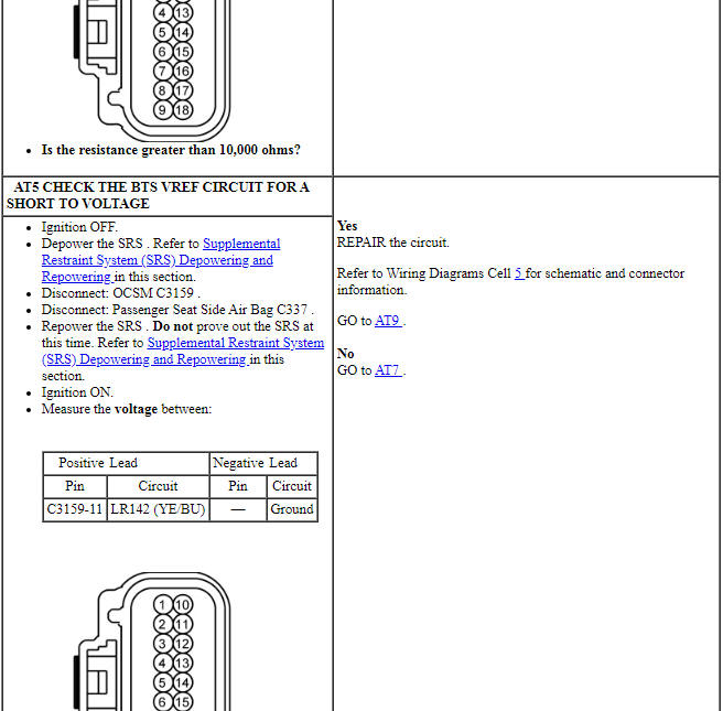
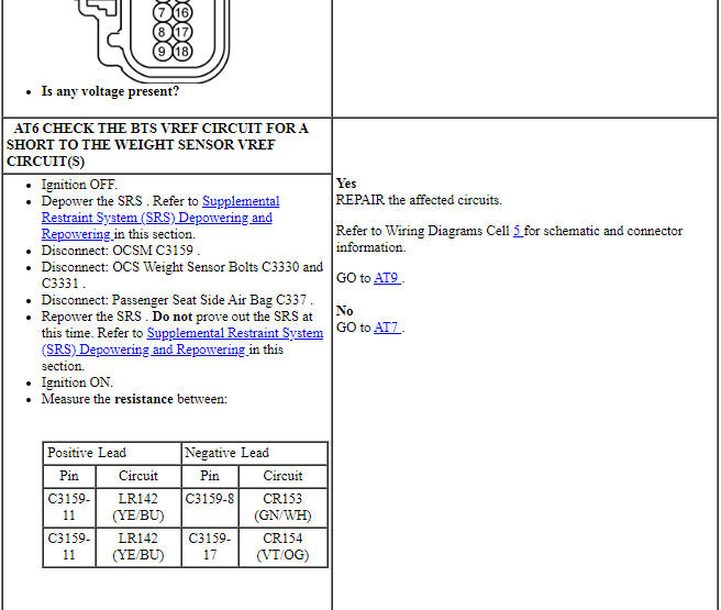
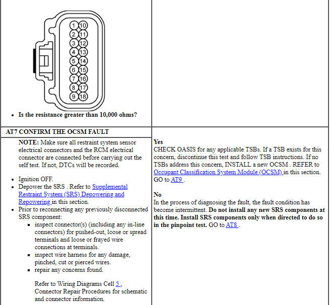
Pinpoint Test AU: DTC U2300:55 and U2300:64
Diagnostic Overview
Diagnostics in this manual assume a certain skill level and knowledge of Ford-specific diagnostic practices. Refer to Diagnostic Methods in Section 100-00 for information about these practices.
Refer to Wiring Diagrams Cell 46, Supplemental Restraint System for schematic and connector information.
NOTE: DTC U2300:55 sets in every new RCM installed until configuration data is successfully received from the BCM. DO NOT install any new components for this DTC unless directed to do so in the pinpoint test.
Normal Operation and Fault Conditions
On the first ignition cycle after a new RCM is installed the BCM sends a configuration data message to the RCM during RCM prove out. During prove-out of each subsequent ignition cycle, the BCM sends configuration data to the RCM and the RCM compares the message to that received during the very first ignition cycle.
-
Possible Sources
- RCM or BCM configuration
- BCM
- RCM
PINPOINT TEST AU: DTC U2300:55 AND U2300:64
WARNING: Do not handle, move or change the original horizontal mounting position of the restraints control module (RCM) while the RCM is connected and the ignition switch is ON. Failure to follow this instruction may result in the accidental deployment of the Safety Canopy and cause serious personal injury or death.
NOTE: SRS components should only be disconnected or reconnected when instructed to do so within a pinpoint test step. Failure to follow this instruction may result in incorrect diagnosis of the SRS.
NOTE: Always make sure the correct SRS component is being installed. Parts released for other vehicles may not be compatible even if they appear physically similar. Check the part number listed in the Ford Catalog Advantage or equivalent to make sure the correct component is being installed. If an incorrect SRS component is installed, DTCs may set.
NOTE: The SRS must be fully operational and free of faults before releasing the vehicle to the customer.
 Specifications, Description and Operation
SPECIFICATIONS
Torque Specifications
DESCRIPTION AND OPERATION
Airbag and Safety Belt Pretensioner Supplemental Restraint System (SRS)
Air Bag and Safety Belt Pretensioner SRS Components (I ...
 General Procedures
Clockspring Adjustment
WARNING: If
the clockspring is not correctly centralized, it may fail prematurely. If in
doubt, repeat the centralizing procedure. Failure to follow these instructions
...
Other materials:
Essential towing checks
Follow these guidelines for safe towing:
• Do not tow a trailer until you drive your vehicle at least 1000 miles
(1600 kilometers).
• Consult your local motor vehicle laws for towing a trailer.
• See the instructions included with towing accessories for the proper
installation and adj ...
Disassembly and Assembly of Subassemblies
Cylinder Head
Special Tool(s)
Material
Disassembly
NOTICE: During engine repair procedures, cleanliness is extremely
important. Any foreign material, including any material created while cleaning
gasket surfaces, that enters the oil passages, coolant passages or the oil pan
can cause en ...
Trip computer
Resetting the Trip Computer
Press and hold OK on the current screen to reset the respective trip,
distance, time and fuel information.
Odometer
Registers the total accumulated distance for the lifetime of the vehicle.
This value cannot be reset.
Trip Odometer
Registers the distance of indiv ...
