Engine
Special Tool(s)
Material
WARNING: Do not smoke, carry lighted tobacco or have an open flame of any type when working on or near any fuel-related component. Highly flammable mixtures are always present and may be ignited. Failure to follow these instructions may result in serious personal injury.
WARNING: Do not carry personal electronic devices such as cell phones, pagers or audio equipment of any type when working on or near any fuel-related component. Highly flammable mixtures are always present and may be ignited. Failure to follow these instructions may result in serious personal injury.
WARNING: When handling fuel, always observe fuel handling precautions and be prepared in the event of fuel spillage. Spilled fuel may be ignited by hot vehicle components or other ignition sources. Failure to follow these instructions may result in serious personal injury.
WARNING: Clean all fuel residue from the engine compartment. If not removed, fuel residue may ignite when the engine is returned to operation. Failure to follow this instruction may result in serious personal injury.
NOTICE: During engine repair procedures, cleanliness is extremely important. Any foreign material, including any material created while cleaning gasket surfaces that enters the oil passages, coolant passages or the oil pan, may cause engine failure.
NOTICE: Whenever turbocharger air intake system components are removed, always cover open ports to protect from debris. It is important that no foreign material enter the system. The turbocharger compressor vanes are susceptible to damage from even small particles. All components should be inspected and cleaned, if necessary, prior to installation or reassembly.
NOTE: A clean working environment is essential to prevent dirt or foreign material contamination into the fuel rails.
NOTE: For additional information, refer to the exploded view under the Assembly procedure in this section.
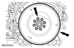
- Remove the 8 bolts and the flexplate.
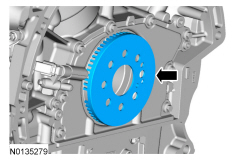
- Remove the crankshaft sensor ring.
- NOTE: Install the engine stand bolts into the cylinder block
only. Do not install the bolts into the oil pan.
Mount the engine on a suitable engine stand.
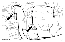
- If equipped, remove the heat shield and disconnect the block heater
electrical connector.
- Detach all of the engine block heater harness retainers and remove the harness.
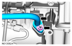
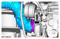
- Remove the nut and the A/C tube from the compressor.
- Discard the O-ring seal and gasket seal.
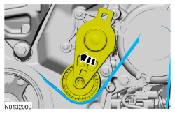
- Rotate the accessory drive belt tensioner clockwise and remove the accessory drive belt.
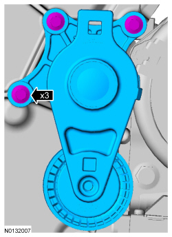
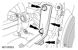
- Remove the 3 bolts and the accessory drive belt tensioner.
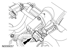
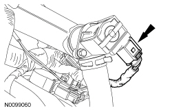
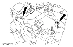
- Disconnect the LH turbocharger bypass valve electrical connector.
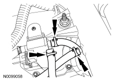
- NOTE: Index-mark the hoses for installation.
Remove the turbocharger wastegate regulating valve hoses from the RH CAC tube and turbocharger wastegate regulating valve.
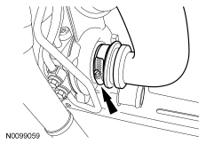
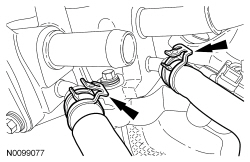
- Loosen the clamp and remove the LH turbocharger intake tube from the LH turbocharger.
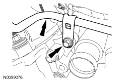
- Disconnect the RH turbocharger bypass valve electrical connector.
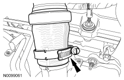
- Loosen the clamp and remove the RH CAC tube from the RH turbocharger.
- Loosen the clamp and remove the RH turbocharger intake pipe from the RH turbocharger.
- NOTICE: The compression limiter bushing may fall out of the
mounting bracket grommet on the turbocharger intake tube during service.
Make sure the bushing is in place when reinstalling the tube or damage to
the tube may occur.
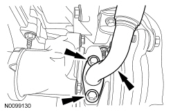
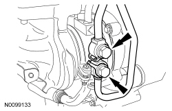
Remove the nut from the RH valve cover stud bolt for the RH turbocharger intake tube.
- NOTICE: The compression limiter bushing may fall out of the
mounting bracket grommet on the Charge Air Cooler (CAC) tube during service.
Make sure the bushing is in place when reinstalling the tube or damage to
the tube may occur.
Remove the RH CAC tube nut from the intake manifold and remove the RH CAC tube and turbocharger intake tube as an assembly.
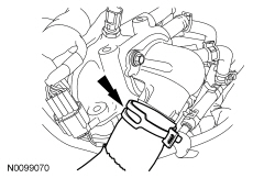
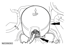
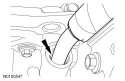
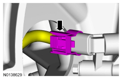
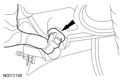
- Remove the lower radiator hose from the thermostat housing.
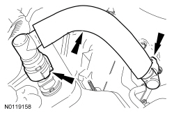
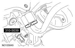
- Disconnect the 2 quick connect couplings and remove the PCV tube. For additional information, refer to Section 310-00.
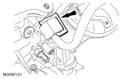
- Remove the noise insulator shield for the fuel injection fuel pump and disconnect the electrical connector.
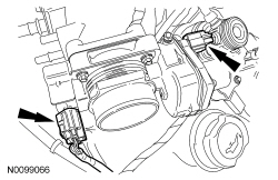
- Disconnect the Throttle Position (TP) sensor and electronic TB electrical connectors.
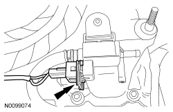
- Disconnect the LH Variable Camshaft Timing (VCT) solenoid electrical connector.
- Disconnect the A/C compressor and the pressure relief valve electrical
connectors.
- Detach the 2 wiring harness retainers from the from the A/C stud bolts.
- Remove the A/C compressor nut and the Catalyst Monitor Sensor (CMS)
electrical connector bracket.
- Detach the CMS electrical connector from the bracket.
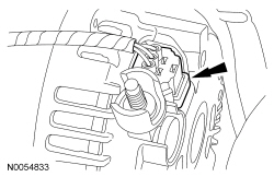
- Remove the nut and disconnect the generator B+ cable.
- Disconnect the generator electrical connector.
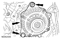
- Remove the nut, bolt and the generator.
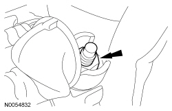
- Remove the generator stud.
- Remove the stud bolt and the A/C compressor.
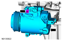
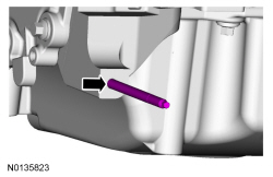
- Remove the A/C compressor mounting stud from the oil pan.
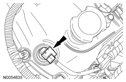
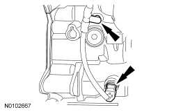
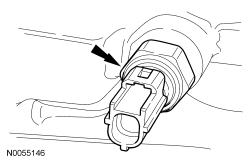
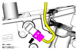
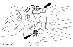
- Disconnect the Engine Oil Pressure (EOP) switch electrical connector.
- Detach the EOP wiring harness retainer from the engine block.
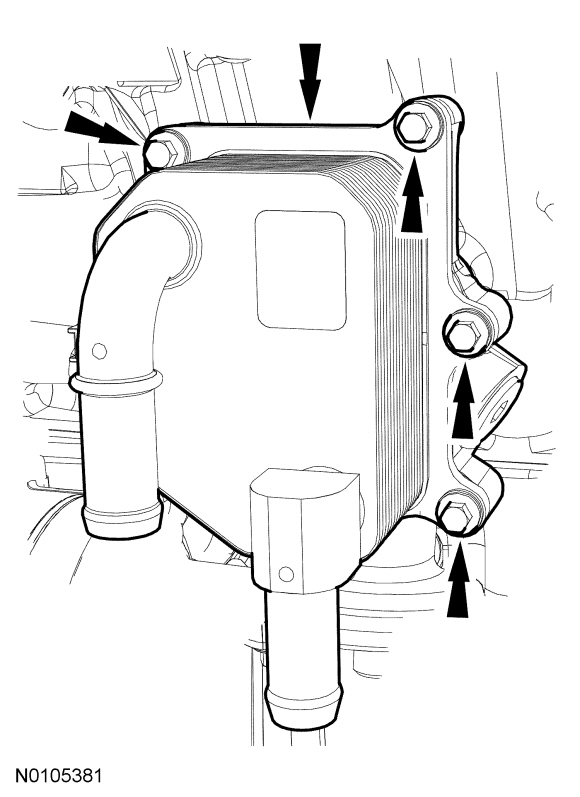
- NOTICE: A new oil cooler must be installed or severe damage to
the engine may occur.
If equipped, remove the 6 bolts and the oil cooler.
- Discard the oil cooler and gaskets.
- NOTE: Engine without oil cooler shown, engine with oil cooler
similar.
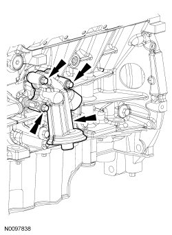
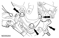
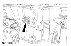
Remove the 3 bolts and the oil filter adapter.
- Discard the gasket.
- Remove the EOP switch.
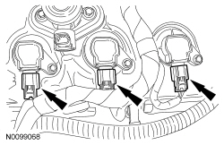
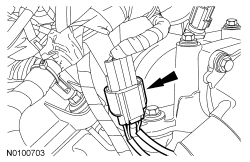
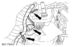
- Disconnect the 3 LH ignition coil-on-plug electrical connectors.
- Detach all the wiring harness retainers from the LH valve cover and stud bolts.
- Remove the oil level indicator.
- Disconnect the Knock Sensor (KS) sensor electrical connector.
- Detach and disconnect the 2 fuel injector wiring harness electrical connectors.
- Disconnect the Manifold Absolute Pressure (MAP)/Intake Air Temperature 2 (IAT2) sensor electrical connector.
- Disconnect the turbocharger wastegate regulating valve electrical connector.
- Detach the 2 wire harness-to-intake manifold retainers.
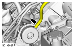
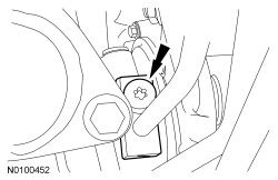
- Remove the fuel tube-to-engine front cover bracket bolt and position the fuel tube aside.
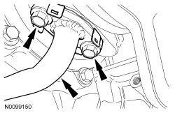
- Disconnect the 2 turbocharger coolant hoses from the intake manifold.
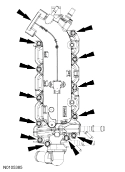
- NOTICE: If the engine is repaired or replaced because of upper
engine failure, typically including valve or piston damage, check the intake
manifold for metal debris. If metal debris is found, install a new intake
manifold. Failure to follow these instructions can result in engine damage.
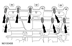
NOTE: Note the routing of the 2 fuel rail wiring harnesses for installation.
Remove the 12 bolts and the intake manifold.- Remove and discard the intake manifold, coolant crossover and thermostat housing gaskets.
- Clean and inspect all sealing surfaces.
- Disconnect the RH VCT solenoid electrical connector and detach the 2 wiring harness retainers.
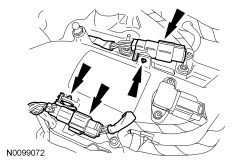
- Disconnect the 3 RH ignition coil-on-plug electrical connectors.
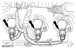
- Detach all the wiring harness retainers from the RH valve cover and stud bolts.
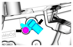
- Disconnect the RH Camshaft Position (CMP) sensor electrical connector.
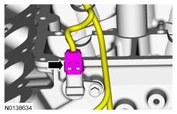
- Remove the bolt and the RH CMP sensor.
- Disconnect the Cylinder Head Temperature (CHT) sensor electrical connector from the rear of the RH cylinder head.
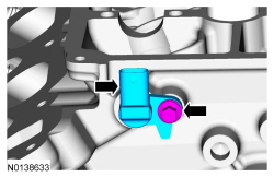
- Disconnect the LH CMP sensor electrical connector.
- Remove the bolt and the LH CMP sensor.
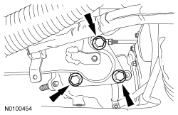
- Disconnect the turbocharger wastegate regulating valve hose from the LH turbocharger assembly.
- Remove the 2 bolts and the LH turbocharger oil return tube from the
turbocharger.
- Remove and discard the gasket.
- Remove the LH turbocharger oil return tube from the oil pan.
- Discard the 2 O-ring seals.
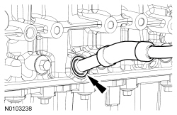
- Remove the LH oil supply tube secondary latch.
- Using the Spring Lock Coupling Disconnect Tool, remove the LH oil supply
tube from the quick connect fitting.
- Inspect and if necessary, replace the quick connect filtering.
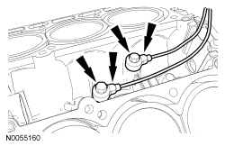
- Remove the 2 coolant tube banjo bolts and the LH turbocharger coolant
tubes and sealing washers.
- Discard the sealing washers.
- Remove the LH turbocharger oil supply tube banjo bolt.
- Discard the sealing washer.
- Discard the oil supply tube filter.
- Remove the 2 bolts and the lower LH turbocharger-to-cylinder block bracket.
- Remove the 2 bolts and the upper LH turbocharger bracket-to-cylinder block bracket.
- Remove the 3 LH turbocharger-to-exhaust manifold bolts and turbocharger.
- Discard the gasket and bolts.
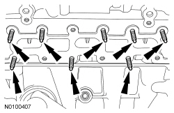
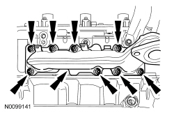
- Remove the 8 LH exhaust manifold nuts (6 shown) and the exhaust
manifold.
- Discard the exhaust manifold gasket and nuts.
- Clean and inspect the LH exhaust manifold. For additional information, refer to Section 303-00.
- Remove and discard the 8 LH exhaust manifold studs.
- NOTICE: Do not use metal scrapers, wire brushes, power
abrasive discs or other abrasive means to clean the sealing surfaces. These
may cause scratches and gouges resulting in leak paths. Use a plastic
scraper to clean the sealing surfaces.
Clean the exhaust manifold mating surface of the cylinder head with metal surface prep. Follow the directions on the packaging.
- Remove the LH coolant tube bracket-to-cylinder head nut.
- Remove the nut and the heat shield.
- Remove the wiring harness retainer stud bolt.
- Remove the wiring harness grommet.
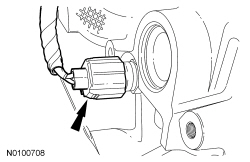
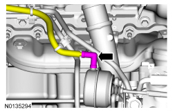
- Disconnect the Crankshaft Position (CKP) sensor electrical connector.
- Remove the bolt and the CKP sensor.
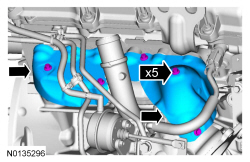
- Remove the 5 bolts and the 2 upper RH exhaust manifold heat shields.
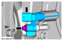
- Disconnect the turbocharger wastegate regulating valve hose from the RH turbocharger assembly.
- Remove the 2 bolts and the RH turbocharger oil return tube from the RH
turbocharger.
- Remove and discard the gasket.
- Remove the RH turbocharger oil return tube from the cylinder block.
- Discard the 2 O-ring seals.
- Remove the RH oil supply tube secondary latch.
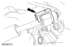
- Using the Spring Lock Coupling Disconnect Tool, remove the RH oil supply
tube from the quick connect fitting.
- Inspect and if necessary, replace the quick connect fitting.
- Remove the 2 coolant tube banjo bolts and the RH turbocharger coolant
tubes.
- Discard the sealing washers.
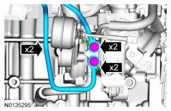
- Remove the 3 bolts and the upper turbocharger-to-cylinder block bracket.
- Remove the 3 exhaust manifold-to-turbocharger bolts and the turbocharger
assembly.
- Discard the gasket and bolts.
- Remove the RH turbocharger oil supply tube banjo bolt.
- Discard the sealing washer.
- Discard the oil supply tube filter.
- Remove the 8 nuts and the RH exhaust manifold.
- Discard the nuts and exhaust manifold gaskets.
- Clean and inspect the RH exhaust manifold. For additional information, refer to Section 303-00.
- Remove and discard the 8 RH exhaust manifold studs.
- NOTICE: Do not use metal scrapers, wire brushes, power
abrasive discs or other abrasive means to clean the sealing surfaces. These
may cause scratches and gouges resulting in leak paths. Use a plastic
scraper to clean the sealing surfaces.
Clean the exhaust manifold mating surface of the cylinder head with metal surface prep. Follow the directions on the packaging.
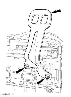
- Remove the 2 bolts and the RH engine lifting eye.
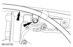
- Remove the RH coolant tube bracket-to-cylinder head bolt and the coolant tube assembly.
- Remove the pin-type retainer and the cover.
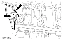
- Detach the wiring harness retainer from the rear of the LH cylinder head.
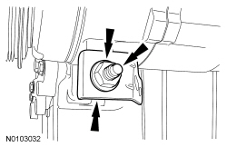
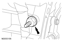
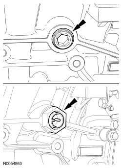
- Remove the LH cylinder block drain plug.
- Allow coolant to drain from the cylinder block.
- Remove the RH cylinder block drain plug or, if equipped, the block
heater.
- Allow coolant to drain from the cylinder block.
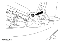
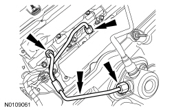
- Remove the nut for the high pressure fuel tube from the LH valve cover stud bolt and disconnect the Fuel Rail Pressure (FRP) sensor electrical connector.
- NOTE: To release the fuel pressure in the high pressure fuel
tube, wrap the flare nuts with a shop towel to absorb any residual fuel
pressure during the loosening of the flare nuts.
Remove the high pressure fuel tube flare nut from the fuel injection pump. Remove the 2 high pressure fuel tube flare nuts from the fuel rails and remove the high pressure fuel tube assembly.
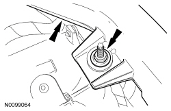
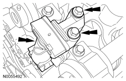
- Remove the 2 bolts and the fuel injection pump.
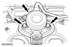
- Remove the fuel injection pump mounting plate.
- NOTE: Valve cover is removed for clarity.
Remove the fuel injection pump roller tappet.
- Inspect the fuel injection pump roller tappet. For additional information, refer to Section 303-04B.
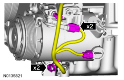
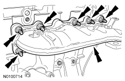
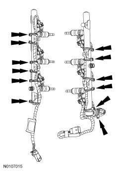
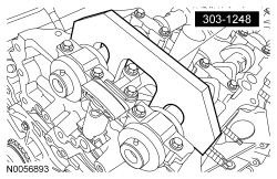
- NOTICE: It is very important to note the routing of the wiring
harness on the fuel rails and index-mark the locations of the tie straps
prior to removal or damage may occur to the wire harnesses during
installation. The illustration details the correct wire harness routing and
tie strap positioning for installation.
NOTE: Use compressed air to remove any dirt or foreign material from the cylinder head, block and the general surrounding area of the fuel rails and injectors.
Carefully cut and remove the fuel rail wire harness tie straps.
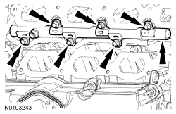
- NOTICE: Pull out the fuel rails in the direction of the fuel
injector axis or damage may occur to the fuel injectors.
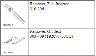
NOTE: When removing the fuel rails, the fuel injectors may remain in the fuel rails but normally remain lodged in the cylinder heads and require the use of a Fuel Injector Remover to extract.
Remove the 6 bolts and the LH fuel rail.
- Remove the 6 bolts and the RH fuel rail.
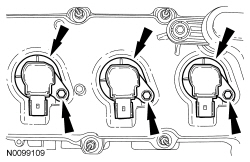
- NOTE: RH shown, LH similar.
Disconnect the 6 fuel injector electrical connectors and remove the 2 fuel injector wire harnesses.
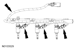
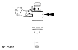
- Remove and discard the 6 upper fuel injector O-ring seals.
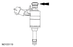
- Remove and discard the 6 fuel injector clips.
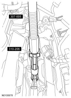
- Using the Slide Hammer and the Fuel Injector Remover, remove the 6 fuel injectors.
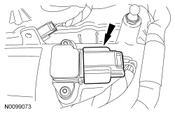
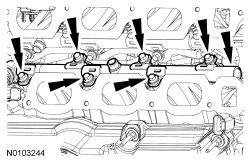
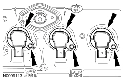
- NOTE: When removing the ignition coil-on-plugs, a slight twisting
motion will break the seal and ease removal.
Remove the 3 bolts and the 3 RH ignition coils-on-plugs.
- NOTE: When removing the ignition coil-on-plugs, a slight twisting
motion will break the seal and ease removal.
Remove the 3 bolts and the 3 LH ignition coils-on-plugs.
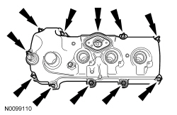
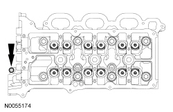
- Loosen the 10 stud bolts and remove the LH valve cover.
- Discard the gasket.
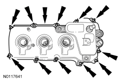
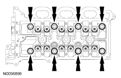
- Loosen the 11 stud bolts and remove the RH valve cover.
- Discard the gasket.
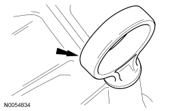
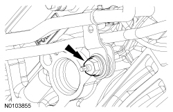
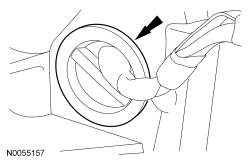
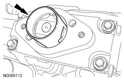
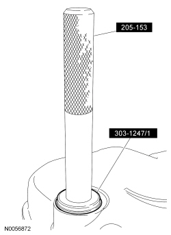
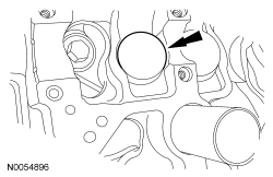
- NOTE: VCT solenoid seal removal shown, spark plug tube seal
removal similar.
Inspect the VCT solenoid seals and the spark plug tube seals. Install new seals if damaged.
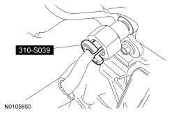
- Using the VCT Spark Plug Tube Seal Remover and Handle, remove the seal(s).
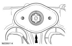
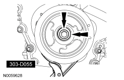
- Using the Strap Wrench, remove the crankshaft pulley bolt and washer.
- Discard the bolt.
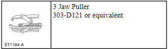
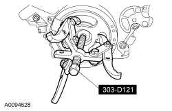
- Using the 3 Jaw Puller, remove the crankshaft pulley.
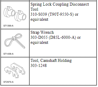
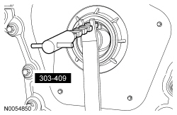
- Using the Oil Seal Remover, remove and discard the crankshaft front seal.
- Remove the stud bolt and Heated Oxygen Sensor (HO2S) connector bracket from the engine front cover.
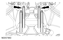
- NOTE: Only use hand tools to remove the studs.
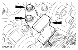
Remove the 2 engine mount studs.
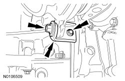
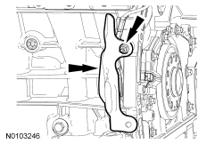
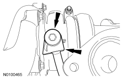
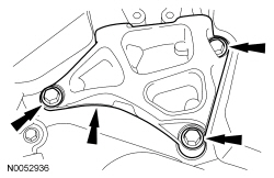
- Remove the 3 bolts and the engine mount bracket.
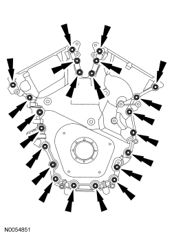
- Remove the 22 engine front cover bolts.
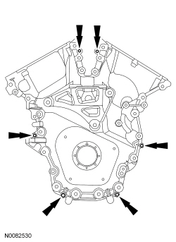
- Install 6 of the engine front cover bolts (finger-tight) into the 6
threaded holes in the engine front cover.
- Tighten the bolts one turn at a time in a crisscross pattern until
the engine front cover-to-cylinder block seal is released.
- Remove the engine front cover.
- Tighten the bolts one turn at a time in a crisscross pattern until
the engine front cover-to-cylinder block seal is released.
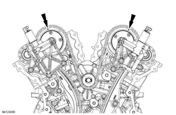
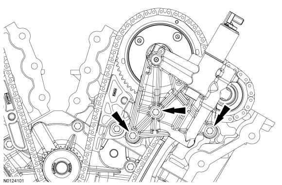
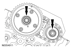
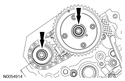
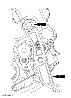
- Rotate the crankshaft clockwise and align the timing marks on the Variable Camshaft Timing (VCT) assemblies as shown.
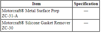
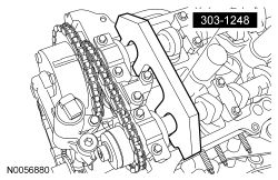
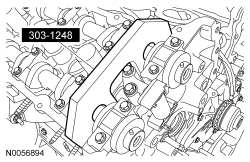
- NOTE: The Camshaft Holding Tool will hold the camshafts in the
Top Dead Center (TDC) position.
Install the Camshaft Holding Tool onto the flats of the LH camshafts.
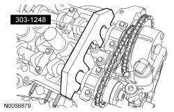
- NOTE: The Camshaft Holding Tool will hold the camshafts in
the TDC position.
Install the Camshaft Holding Tool onto the flats of the RH camshafts.
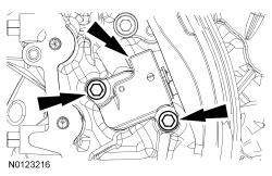
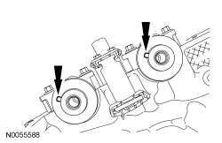
- Remove the 3 bolts and the RH VCT housing.
- Remove the 3 bolts and the LH VCT housing.
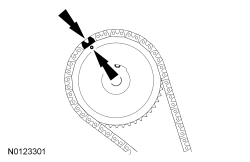
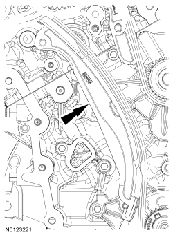
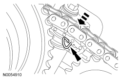
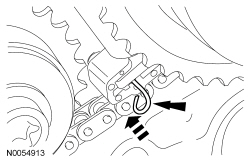
NOTE: The following 3 steps are for primary timing chains when the colored links are not visible.
- Mark the timing chain link that aligns with the timing mark on the RH intake VCT assembly as shown.
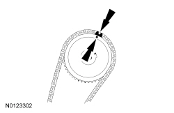
- Mark the timing chain link that aligns with the timing mark on the LH intake VCT assembly as shown.
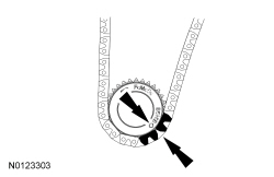
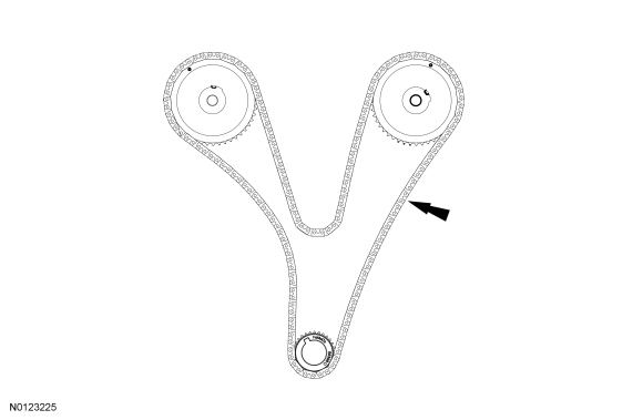
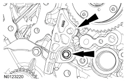
- NOTE: The crankshaft sprocket timing mark should be between the 2
colored links.
Mark the 2 timing chain links that align with the timing mark on the crankshaft sprocket as shown.
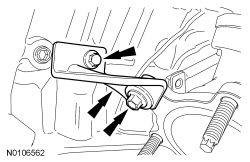
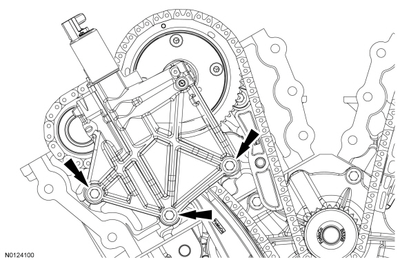
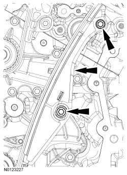
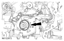
- Remove the 2 bolts and the primary timing chain tensioner.
- Remove the primary timing chain tensioner arm.
- Remove the 2 bolts and the lower LH primary timing chain guide.
- Remove the primary timing chain.
- Remove the crankshaft timing chain sprocket.
- Remove the bolt and the upper LH primary timing chain guide.
- Compress the LH secondary timing chain tensioner and install a suitable lockpin to retain the tensioner in the collapsed position.
- NOTE: The VCT bolt and the exhaust camshaft bolt must be
discarded and new ones installed. However, the exhaust camshaft washer is
reusable.
Remove and discard the LH VCT assembly bolt and the LH exhaust camshaft sprocket bolt.
- Remove the LH VCT assembly, secondary timing chain and the LH exhaust camshaft sprocket as an assembly.
- NOTE: When the Camshaft Holding Tool is removed, valve spring
pressure will rotate the LH camshafts approximately 3 degrees to a neutral
position.
Remove the Camshaft Holding Tool from the LH camshafts.
- NOTICE: The camshafts must remain in the neutral position
during removal or engine damage may occur.
Verify the LH camshafts are in the neutral position.
- Remove the 2 bolts and the LH secondary timing chain tensioner.
- NOTE: Cylinder head camshaft bearing caps are numbered to verify
that they are assembled in their original positions.
Remove the bolts and the LH camshaft bearing caps.
- Remove the LH camshafts.
- Compress the RH secondary timing chain tensioner and install a suitable lockpin to retain the tensioner in the collapsed position.
- NOTE: The VCT bolt and the exhaust camshaft bolt must be
discarded and new ones installed. However, the exhaust camshaft washer is
reusable.
Remove and discard the RH VCT assembly bolt and the RH exhaust camshaft sprocket bolt.
- Remove the RH VCT assembly, secondary timing chain and the RH exhaust camshaft sprocket as an assembly.
- Remove the Camshaft Holding Tool from the RH camshafts.
- NOTICE: The camshafts must remain in the neutral position
during removal or engine damage may occur.
Rotate the RH camshafts counterclockwise to the neutral position.
- Remove the 2 bolts and the RH secondary timing chain tensioner.
- Remove the bolt and the RH timing chain guide.
- NOTE: Cylinder head camshaft bearing caps are numbered to verify
that they are assembled in their original positions.
Remove the bolts and the RH camshaft bearing caps.
- Remove the RH camshafts.
- NOTE: If the components are to be reinstalled, they must be
installed in the same positions. Mark the components for installation into
their original locations.
NOTE: LH shown, RH similar.
Remove the valve tappets from the cylinder heads.
- NOTE: LH shown, RH similar.
Remove and discard the M6 bolt from each cylinder head.
- NOTICE: Place clean, lint-free shop towels over exposed engine
cavities. Carefully remove the towels so foreign material is not dropped
into the engine. Any foreign material (including any material created while
cleaning gasket surfaces) that enters the oil passages or the oil pan, may
cause engine failure.
NOTICE: Aluminum surfaces are soft and may be scratched easily. Never place the cylinder head gasket surface, unprotected, on a bench surface.
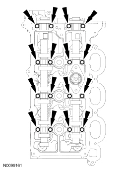
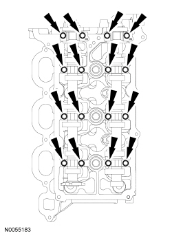
NOTE: The cylinder head bolts must be discarded and new bolts must be installed. They are a torque-to-yield design and cannot be reused.
NOTE: LH shown, RH similar.
Remove and discard the 8 bolts from each cylinder head.- Remove the cylinder heads.
- Discard the cylinder head gaskets.
- NOTICE: Do not use metal scrapers, wire brushes, power
abrasive discs or other abrasive means to clean the sealing surfaces. These
tools cause scratches and gouges that make leak paths. Use a plastic
scraping tool to remove all traces of the head gasket.
NOTE: Observe all warnings or cautions and follow all application directions contained on the packaging of the silicone gasket remover and the metal surface prep.
NOTE: If there is no residual gasket material present, metal surface prep can be used to clean and prepare the surfaces.
Clean the cylinder head-to-cylinder block mating surfaces of both the cylinder heads and the cylinder block in the following sequence.- Remove any large deposits of silicone or gasket material with a plastic scraper.
- Apply silicone gasket remover, following package directions, and allow to set for several minutes.
- Remove the silicone gasket remover with a plastic scraper. A second application of silicone gasket remover may be required if residual traces of silicone or gasket material remain.
- Apply metal surface prep, following package directions, to remove any remaining traces of oil or coolant and to prepare the surfaces to bond with the new gasket. Do not attempt to make the metal shiny. Some staining of the metal surfaces is normal.
- Support the cylinder head on a bench with the head gasket side up. Check the cylinder head distortion and the cylinder block distortion. For additional information, refer to Section 303-00.
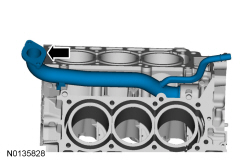
- Remove the coolant inlet tube.
- Remove and discard the O-ring seal.
- Remove the 2 bolts and the KS.
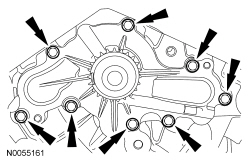
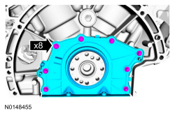
- Remove the 8 bolts and the coolant pump.
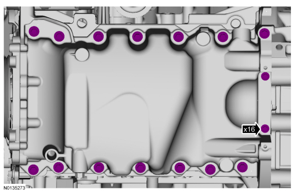
- Remove the 16 oil pan bolts.
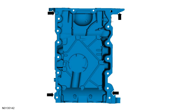
- Using a suitable pry tool, locate the pry pads and pry the oil pan loose and remove.
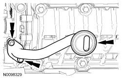
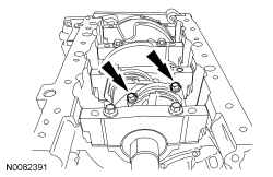
- Remove the 2 bolts and the oil pump screen and pickup tube.
- Discard the O-ring seal.
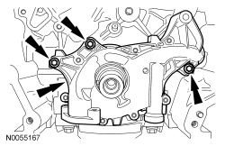
- Remove the 3 bolts and the oil pump.
- Remove the 8 bolts and the crankshaft rear seal retainer plate.
- Discard the plate and seal assembly.
- NOTICE: Only use a 3M Roloc Bristle Disk (2-in white, part
number 07528) to clean the engine front cover, oil pan and crankshaft rear
seal retainer plate. Do not use metal scrapers, wire brushes or any other
power abrasive disk to clean the engine front cover and oil pan. These tools
cause scratches and gouges that make leak paths.
Clean the engine front cover and oil pan using a 3M Roloc Bristle Disk (2-in white, part number 07528) in a suitable tool turning at the recommended speed of 15,000 rpm.
- Thoroughly wash the engine front cover and oil pan to remove any foreign material, including any abrasive particles created during the cleaning process.
- Before removing the pistons, inspect the top of the cylinder bores. If necessary, remove the ridge or carbon deposits from each cylinder using an abrasive pad or equivalent, following manufacturer's instructions.
- NOTE: The main bearing cap support brace bolts must be discarded
and new bolts must be installed. They are a tighten-to-yield design and
cannot be reused.
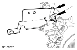
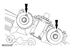
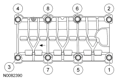
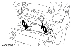
Remove the bolts in the sequence shown.
- Remove the main bearing cap support brace.
- Discard the bolts.
- NOTE: The connecting rod cap bolts are a torque-to-yield design.
The original connecting rod cap bolts will be used when measuring the
connecting rod large end bore during assembly. The connecting rod cap bolts
will be discarded after measurement.
NOTE: Clearly mark the position and orientation of the connecting rods, connecting rod caps and connecting rod bearings for reassembly.
Remove the connecting rod cap bolts and cap.
- NOTICE: Do not scratch the cylinder walls or crankshaft
journals with the connecting rod.
Remove the piston/rod assembly from the engine block.
- Repeat the previous 2 steps until all the piston/rod assemblies are removed from the engine block.
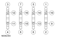
- NOTE: The 8 main bearing cap side bolts and the 8 main bearing
cap bolts must be discarded and new bolts must be installed. They are a
tighten-to-yield design and cannot be reused.
NOTE: Clearly mark the position and orientation of the main bearing caps for reassembly.
Remove the 8 main bearing cap side bolts and the 8 main bearing cap bolts in the sequence shown.- Discard the bolts.
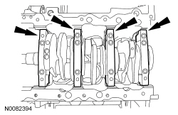
- NOTE: If the main bearings are being reused, mark them for
correct position and orientation for reassembly.
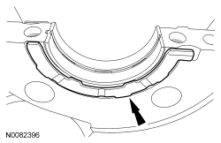
NOTE: Note the position of the thrust washer on the outside of the No. 4 rear main bearing cap.
Remove the 4 main bearing caps.
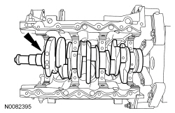
- NOTE: Note the position of the 2 thrust washers on the inside and
outside of the rear main bearing bulkhead.
Remove the crankshaft.
- NOTE: Inside shown, outside similar.
Remove the 2 crankshaft thrust bearings from the rear main bearing bulkhead.
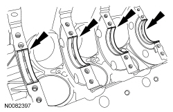
- NOTE: If the main bearings are being reused, mark them for
correct position and orientation for reassembly.
Remove the 4 crankshaft main bearings from the cylinder block.
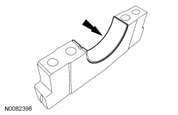
- NOTE: If the main bearings are being reused, mark them for
correct position and orientation for reassembly.
Remove the 4 crankshaft main bearings from the main bearing caps.
- Inspect the cylinder block, bearing cap support brace, pistons and connecting rods. For additional information, refer to Section 303-00.
- NOTICE: Place clean, lint-free shop towels over exposed engine
cavities. Carefully remove the towels so foreign material is not dropped
into the engine. Any foreign material (including any material created while
cleaning gasket surfaces) that enters the oil passages or the oil pan, may
cause engine failure.
NOTICE: Do not use wire brushes, power abrasive discs or 3M Roloc Bristle Disk (2-in white, part number 07528) to clean the sealing surfaces. These tools cause scratches and gouges that make leak paths. They also cause contamination that will cause premature engine failure. Remove all traces of sealant.
Clean the sealing surfaces of the cylinder block in the following sequence.- Remove any large deposits of silicone or gasket material.
- Apply silicone gasket remover and allow to set for several minutes.
- Remove the silicone gasket remover. A second application of silicone gasket remover may be required if residual traces of silicone or gasket material remain.
- Apply metal surface prep to remove any remaining traces of oil or coolant and to prepare the surfaces to bond. Do not attempt to make the metal shiny. Some staining of the metal surfaces is normal.
- Make sure the 2 engine front cover locating dowel pins are seated correctly in the cylinder block.
 Removal
Engine
Special Tool(s)
WARNING: Do not smoke, carry lighted tobacco or have an open flame of any
type when working on or near any fuel-related component. Highly flammable
mixtures are always ...
 Disassembly and Assembly of Subassemblies
Cylinder Head
Special Tool(s)
Material
Cylinder Head
NOTE: RH shown, LH similar.
Disassembly
NOTE: If the components are to be reinstalled, they must be installed
in the same positions ...
Other materials:
Front End Body Panels
SPECIFICATIONS
Torque Specifications
DESCRIPTION AND OPERATION
Active Grille Shutter System
Overview
The grille shutter system (when equipped) is comprised of the grille shutter
assembly and the grille shutter actuator. The grille shutter system is primarily
used to maximize fuel economy by reduc ...
Safety Warnings
Review carefully the General Service Health and Safety Precautions below before
beginning any repair. Following these general service warnings are specific
system warnings that must be carefully reviewed before beginning work on any
listed system.
General Service Health and Safety Precautions
& ...
Description and Operation
Instrument Panel Cluster (IPC)
Overview
Base IPC
Tachometer
Main menu navigation
Main menu text display
LH turn indicator
TPMS warning indicator
MIL
Stability-traction control indicator (sliding car icon)
Stability-traction control disabled indicator (sliding car OFF icon)
Air b ...
