SPECIFICATIONS
Alignment Specifications
a Camber Total/Split = LH Camber - RH Camber
b Caster Total/Split = LH Caster - RH Caster
General Specifications
Torque Specifications
DESCRIPTION AND OPERATION
Wheel Alignment Angles
Camber
Negative and Positive Camber
Camber is the vertical tilt of the wheel when viewed from the front. Camber can be positive or negative and has a direct effect on tire wear.
Caster
Caster is the deviation from vertical of an imaginary line drawn through the pivot points (top of strut and lower ball joint), when viewed from the side. The caster specifications in this section will give the vehicle the best directional stability characteristics when loaded and driven. The caster setting is not related to tire wear. The caster setting is not adjustable.
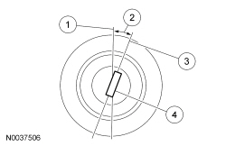
- True vertical
- Positive caster angle
- Strut-to-ball joint centerline
- Pivot centerline
A backward tilt is positive (+) and a forward tilt is negative (-). Front caster adjustment is not a separate procedure on this vehicle. The vehicle will tend to drift/pull toward the side with the lowest caster.
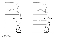
Toe
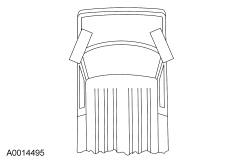
Positive Toe (Toe In)
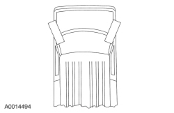
Negative Toe (Toe Out)
The vehicle toe setting affects tire wear and directional stability.
Incorrect Thrust Angle (Dogtracking)
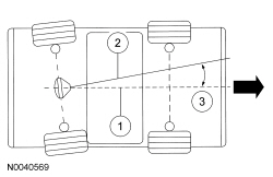
- Vehicle centerline
- Axle centerline
- Thrust angle
Incorrect thrust angle (also known as dogtracking) is the condition in which the rear axle is not square to the chassis. Heavily crowned roads can give the illusion of dogtracking.
Wander
Wander is the tendency of the vehicle to require frequent, random left and right steering wheel corrections to maintain a straight path down a level road.
Shimmy
Shimmy, as experienced by the driver, is large, consistent, rotational oscillations of the steering wheel resulting from large, side-to-side (lateral) tire/wheel movements.
Shimmy is usually experienced near 64 km/h (40 mph), and can begin or be amplified when the tire contacts pot holes or irregularities in the road surface.
Nibble
Sometimes confused with shimmy, nibble is a condition resulting from tire interaction with various road surfaces and experienced by the driver as small rotational oscillations of the steering wheel.
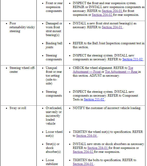
Poor Returnability/Sticky Steering
Poor returnability and sticky steering are used to describe the poor return of the steering wheel to center after a turn or steering correction.
Drift/Pull
Pull is a tugging sensation felt by the hands on the steering wheel that must be overcome to keep the vehicle going straight.
Drift describes what a vehicle with this condition does with the hands off the steering wheel.
- A vehicle-related drift/pull on a flat road causes a consistent deviation from the straight-ahead path and requires constant steering input in the opposite direction to counteract the effect.
- Drift/pull may be induced by conditions external to the vehicle (for example, wind or road crown).
Poor Groove Feel
Poor groove feel is characterized by little or no buildup of turning effort felt in the steering wheel as the wheel is rocked slowly left and right within very small turns around center or straight-ahead (under 20 degrees of steering wheel turn). Effort may be said to be "flat on-center."
- Under 20 degrees of turn, most of the turning effort that builds up comes from the mesh of the gear teeth in the steering gear. In this range, the steering wheel is not yet turned enough to feel the effort from the self-aligning forces at the road wheel or tire patch.
- In the diagnosis of a driveability problem, it is important to understand the difference between wander and poor groove feel.
DIAGNOSIS AND TESTING
Suspension System
Material
Inspection and Verification
- Road test the vehicle.
- If any suspension alignment or ride height concerns are present, GO to Symptom Chart - Suspension System.
- Verify the customer concern by carrying out a road test on a smooth road. If any vibrations are present, GO to Symptom Chart - NVH.
- Inspect the tires.
- Check the tire pressures with all normal loads in the vehicle and the tires cold. Refer to the Vehicle Certification (VC) label.
- Verify that all tires are sized to specification. Refer to the VC label.
- Inspect the tires for incorrect wear and damage. Install new tires as necessary.
- Inspect the chassis and underbody.
- Remove any excessive accumulation of mud, dirt or road deposits from the chassis and underbody.
- Inspect for aftermarket equipment.
- Check for aftermarket changes to the steering, suspension, and wheel and tire components (such as competition or heavy duty). The specifications shown in this manual do not apply to vehicles equipped with aftermarket equipment.
Mechanical
- Front or rear suspension components
- Suspension fastener(s)
- Incorrect spring usage
- Spring(s)
- Shock absorber(s)
- Strut(s)
- Suspension bushing(s)
- Steering system components
- Wheel bearing and wheel hub(s)
- Non-OEM parts or modifications
- If an obvious cause for an observed or reported condition is found, correct the cause (if possible) before proceeding to the next step.
- If the fault is not visually evident, GO to Symptom Chart - Suspension System or GO to Symptom Chart - NVH.
Symptom Chart - Suspension System
Symptom Chart - NVH
NOTE: NVH symptoms should be identified using the diagnostic tools that are available. For a list of these tools, an explanation of their uses and a glossary of common terms, refer to Section 100-04. Since it is possible any one of multiple systems may be the cause of a symptom, it may be necessary to use a process of elimination type of diagnostic approach to pinpoint the responsible system. If this is not the causal system for the symptom, refer back to Section 100-04 for the next likely system and continue diagnosis.
Pinpoint Tests
Pinpoint Test A: Vehicle Drifts/Pulls
-
This pinpoint test is intended to diagnose the following:
- Unevenly loaded vehicle
- Tire pressure
- Tire forces
- Brake drag
- Incorrect vehicle alignment
- Steering system
PINPOINT TEST A: VEHICLE DRIFTS/PULLS
Component Tests
Ball Joint Inspection
- Prior to inspecting the ball joints for wear, inspect the wheel bearings. Install a new wheel bearing as necessary. Refer to Section 204-01.
- NOTE: In order to obtain accurate measurements, the suspension
must be in full rebound with the weight of the vehicle supported by the
frame.
Raise and support the vehicle by the frame to allow the wheels to hang in the rebound position.
- Inspect the ball joint and ball joint boot for damage.
- If the ball joint or ball joint boot is damaged, install a new ball joint as necessary. Refer to Section 204-01.
- NOTICE: Do not use any tools or equipment to move the wheel
and tire assembly or suspension components while checking for relative
movement. Suspension damage may occur. The use of tools or equipment will
also create relative movement that may not exist when using hand force.
Relative movement must be measured using hand force only.
Inspect the ball joint for relative movement by alternately pulling downward and pushing upward on the lower control arm by hand. Note any relative vertical movement between the wheel knuckle and lower arm at the lower ball joint.
- If relative movement is not felt or seen, the ball joint is OK. Do not install a new ball joint.
- If relative movement is found, continue with Step 5.
- NOTE: In order to obtain an accurate measurement, the dial
indicator should be aligned as close as possible with the vertical axis
(center line) of the ball joint.
To measure ball joint deflection, attach a suitable dial indicator with a flexible arm between the lower control arm and the wheel knuckle or ball joint stud.
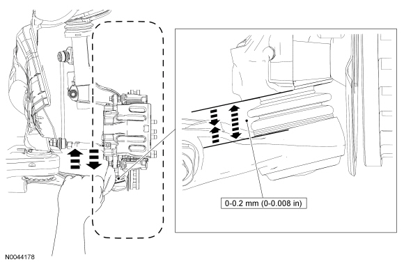
- Measure the ball joint deflection while an assistant pushes up and pulls
down on the lower control arm, by hand.
- If the deflection exceeds the specification, a new ball joint must be installed. Refer to Section 204-01.
- If the deflection meets the specification, no further action is required.
GENERAL PROCEDURES
Ride Height Measurement
Front Ride Height Measurement
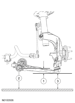
- Ride height = 2 - 3
- Measurement 2
- Measurement 3
NOTE: Make sure that the vehicle is positioned on a flat, level surface and the tires are inflated to the correct pressure. The vehicle should have a full tank of fuel.
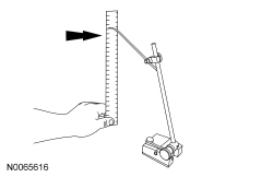
- Position a suitable surface gauge (such as Starrett 57D Surface Gauge)
on a flat, level surface, adjust the gauge's arm until the scriber point is
located in the center of the forward lower arm bolt.
- Lock the surface gauge in this position.
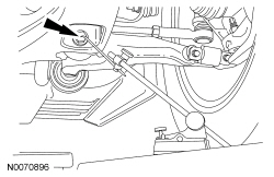
- With the surface gauge positioned on a flat, level surface, record the measurement of the surface gauge position (measurement 2).
- Position the surface gauge on the same flat, level surface and adjust
the gauge's arm until the scriber point is located on the lowest and
furthest inboard point of the lower ball joint.
- Lock the surface gauge in this position.
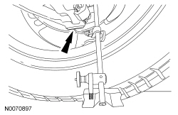
- With the surface gauge positioned on a flat, level surface, record the measurement of the surface gauge position (measurement 3).

- Subtract measurement 3 from measurement 2 to obtain the front ride
height.
- Refer to Specifications in this section.
Rear Ride Height Measurement
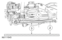
- Ride height = 2 - 3
- Measurement 2
- Measurement 3
NOTE: Make sure that the vehicle is positioned on a flat, level surface and the tires are inflated to the correct pressure. The vehicle should have a full tank of fuel.
- Measure the distance between the flat level surface and the center of the lower control arm-to-subframe bolt (measurement 2).
- Measure the distance between the same flat level surface and the center of the lower arm-to-knuckle bolt (measurement 3).
- Subtract measurement 3 from measurement 2 to obtain the rear ride
height.
- Refer to Specifications in this section.
Camber Adjustment - Front
NOTICE: Suspension fasteners are critical parts that affect the performance of vital components and systems. Failure can result in major service expense. When replacing suspension fasteners, use the same part number or an equivalent part number. Do not use a replacement part of lesser quality or substitute design. Torque values must be used as specified during reassembly to make sure of correct retention of these parts.
NOTE: Before carrying out a camber adjustment, check the tires for the correct pressure. Inspect the tires for incorrect wear or damage. Inspect the front suspension components for wear or damage.
- Using alignment equipment and the manufacturer's instructions, measure the front camber.
NOTICE: Do not use power tools to remove the stabilizer bar link nuts. Damage to the stabilizer bar link ball joints or boots may occur.
NOTE: To remove the stabilizer bar link nuts, first loosen the nuts, then use the hex-holding feature to prevent the stabilizer bar link ball joints from turning while removing the stabilizer bar link nuts.
- Remove and discard the stabilizer bar link upper nut and disconnect the stabilizer bar link.
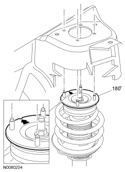
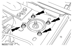
- Remove the strut upper mount nuts.

- NOTE: Do not rotate the strut mount to any other position than
180 degrees from its original position, the notch (located on top of the
strut mount) must either point inward (towards the engine) or outward
(towards the fender).
Push the strut mount downward and rotate it 180 degrees. When rotated 180 degrees from the original position, camber changes by 0.5 degrees.
- Install the strut upper mount nuts.
- Tighten to 63 Nm (46 lb-ft).
NOTE: To install the nuts, use the hex-holding feature to prevent the stabilizer link ball joints from turning while installing the nuts until snug. Finally, tighten the nuts using a socket and a torque wrench.
- Connect the stabilizer bar link and install a new stabilizer bar link
upper nut.
- Tighten the new nut to 150 Nm (111 lb-ft).
- Recheck the camber settings and adjust as necessary.
Camber Adjustment - Rear
NOTICE: Suspension fasteners are critical parts because they affect performance of vital components and systems and their failure may result in major service expense. New parts must be installed with the same part numbers or equivalent part, if replacement is necessary. Do not use a replacement part of lesser quality or substitute design. Torque values must be used as specified during reassembly to make sure of correct retention of these parts.
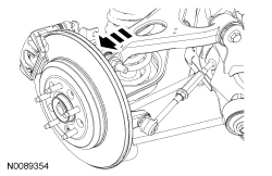
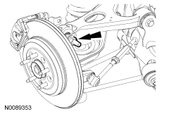
NOTE: To allow for rear camber adjustment, the upper arm is slotted at the upper arm-to-wheel knuckle joint. Rear camber is adjusted from the factory with the wheel knuckle pushed inboard for maximum negative camber. If the camber is more negative than specification, the top of the wheel knuckle should be positioned outboard to adjust the rear camber to the positive position.
- Using alignment equipment and the manufacturer's instructions, measure the rear camber.
- Loosen the upper arm-to-wheel knuckle nut.

- Position the wheel knuckle outboard to adjust the rear camber to the positive camber position.
- Tighten the upper arm-to-wheel knuckle nut to 200 Nm (148 lb-ft).
- Recheck the rear camber and toe.
- Adjust as necessary.
Toe Adjustment - Front
- Using alignment equipment and the manufacturer's instructions, measure the front toe.
- Start the engine and center the steering wheel.
- Turn the engine OFF and, using a suitable steering wheel holding device, lock the steering wheel in the straight-ahead position.
- Remove the steering gear bellows clamps.
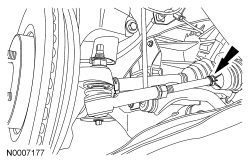
- Loosen the nuts.
- NOTE: Do not allow the steering gear bellows to twist when the
tie rod is rotated.
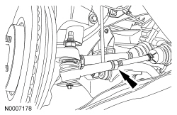
Rotate the tie rods as necessary to adjust the toe setting.
- Tighten the tie-rod jam nuts to 63 Nm (46 lb-ft).

- Recheck the toe settings and adjust as necessary.
- Install the steering gear bellows clamps.
Toe Adjustment - Rear
- Using alignment equipment and the manufacturer's instructions, measure the rear toe.
- Start the engine and center the steering wheel.
- Turn the engine OFF and, using a suitable steering wheel holding device, lock the steering wheel in the straight-ahead position.
- Loosen the tie-rod jam nuts.
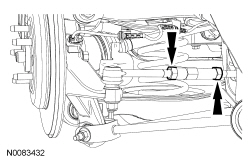
- Rotate the toe link adjusting rod until the toe setting is within specifications.
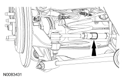
- NOTE: Do not allow the adjusting rod to rotate while tightening
the jam nuts.
Tighten the tie-rod jam nuts to 40 Nm (30 lb-ft).
- Recheck the rear toe and adjust as necessary.
 Suspension
...
 Front Suspension
SPECIFICATIONS
Material
Torque Specifications
a Refer to the procedure in this section.
DESCRIPTION AND OPERATION
Front Suspension
The front suspension consists of the following components:
W ...
Other materials:
Specifications, Description and Operation, Diagnosis and Testing
SPECIFICATIONS
Material
General Specifications
Torque Specifications
a Refer to the procedure in this section.
b 15 Nm plus an additional 60 degrees
c 8 Nm plus an additional 180 degrees
DESCRIPTION AND OPERATION
Engine
Overview
The 2.0L GTDI 4-cylinder engine has ...
Power Steering
SPECIFICATIONS
Torque Specifications
a Refer to the procedure for the specification.
REMOVAL AND INSTALLATION
Steering Gear
Special Tool(s)
NOTE: 3.5L GTDI engine shown, 3.5L Ti-VCT, 3.7L Ti-VCT and 2.0L GTDI similar.
Removal
All vehicles
If in ...
Diagnosis and Testing
Seating
Special Tool(s)
Medium Speed Controller Area Network (MS-CAN)
This vehicle utilizes a communication system called a Medium Speed Controller
Area Network (MS-CAN). When diagnosing the memory seat, heated seats or climate
controlled seats, use a Vehicle Communication Module (VCM) and Integr ...
