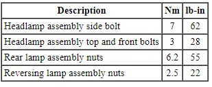
SPECIFICATIONS
Torque Specifications
DESCRIPTION AND OPERATION
Headlamps
Overview
The headlamp system consists of:
- Headlamp assemblies
- Ballasts ( HID only)
- Headlamp switch
- Multifunction switch
- BCM
- SCCM
The headlamp system is a dual-beam pattern system. It consists of a single replaceable headlamp bulb in each headlamp assembly. The vehicle may come equipped with halogen or HID bulbs. The park/turn and side marker lamps are integrated into the headlamp assembly.
System Operation
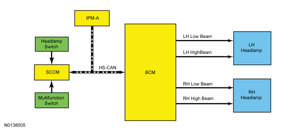
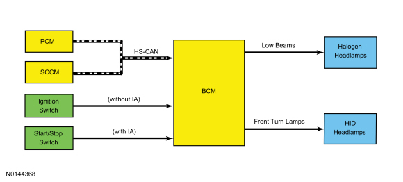
System Diagram
Network Message Chart
BCM Network Input Messages
SCCM Network Input Messages
Battery Saver
NOTE: The battery saver time-out is 1 minute if the vehicle has less than 201 km (125 mi).
NOTE: The battery saver does not control the parking lamps if the headlamp switch is in the parking lamps on position.
To save battery voltage, the BCM provides automatic shut-off of the interior and exterior lamps after a time-out period when the ignition is off. The BCM monitors the ignition state and input from the RKE system to determine when to energize or de-energize the battery saver relay and to shut the power off to the lamps. A timer in the BCM starts when:
- the ignition changes to OFF,
- any door becomes ajar while the ignition is off,
- an UNLOCK button of the RKE transmitter is pressed while the ignition is off,
- a valid keypad code is entered while the ignition is off,
- or the courtesy lamp switch is used to turn the courtesy lamps on while the ignition is off.
When 10 minutes have elapsed, the BCM automatically shuts off voltage to the lamps. The timer restarts (voltage is restored if the BCM is in battery saver mode) if:
- the ignition transitions out of OFF,
- any door becomes ajar,
- the UNLOCK button of the RKE transmitter is pressed,
- a valid keypad code is entered,
- or the courtesy lamp switch is pressed.
Low Beams
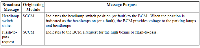
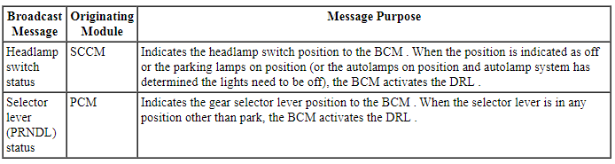
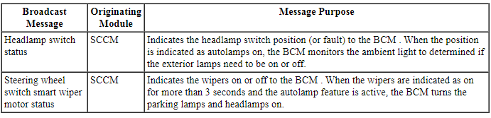
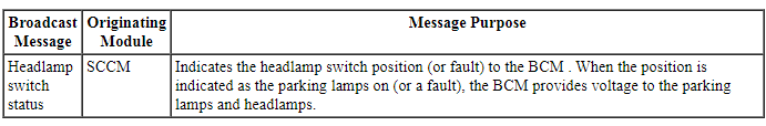
The SCCM monitors the headlamp switch position and sends a headlamp switch status message over the communication network to the BCM to indicate the headlamp switch status (position or a fault with the headlamp switch).
The BCM turns the parking lamps and headlamps on if it loses communication with the SCCM, or if the SCCM detects a fault from the headlamp switch. The head lights will remain on until the battery saver feature times out (refer to Battery Saver in this section).
When the BCM receives a message requesting the headlamps on, it supplies voltage to the headlamp bulbs (halogen headlamps) or the ballasts ( HID headlamps) within each headlamp assembly.
Vehicles with halogen headlamps use single filament bulbs.
Vehicles with HID headlamps utilize a ballast, mounted to each headlamp assembly, to provide the necessary voltage to illuminate the HID bulbs.
The BCM also provides an overload protection of the low beam output circuits. When an excessive current draw is detected, the BCM disables the affected low beam circuit driver. For additional information, refer to FET in Section 419-10.
High Beams
The SCCM monitors the multifunction switch for a high beam or flash-to-pass request. When the multifunction switch is in the high beam or flash-to-pass position, the SCCM sends a high beam flash-to-pass request message to the BCM over the communication network indicating the request.
When the low beams are on and the BCM receives a request for high beams, the headlamps remain powered and the shutter within each headlamp is activated. This changes the headlamp beam pattern to illuminate a greater distance.
The BCM also provides an overload protection of the high beam output circuits. When an excessive current draw is detected, the BCM disables the affected high beam circuit driver. For additional information, refer to FET in Section 419-10.
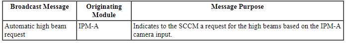
Automatic High Beams
The automatic high beam system uses an interior rear view mirror mounted camera to monitor surrounding traffic conditions and high beam usage. The automatic high beam feature is active only when the headlamp switch is in the AUTOLAMPS position.
The automatic high beams can be enabled/disabled in the IPC message center through the following process:
- From the message center main menu, use the up and down arrow buttons to scroll to and select Settings. Press the OK button.
- Use the up and down arrow buttons to scroll to and select Vehicle. Press the OK button.
- Use the up and down arrow buttons to scroll to and select Auto High Beam. Press the OK button.
- Use the up and down arrow buttons to scroll to and select either On or Off. Press the OK button.
During nighttime driving, the automatic high beam system automatically turns the high beams on if it is dark enough and no other traffic is present. When the system detects an approaching vehicle's headlamps or a preceding vehicle's rear lamps, the system turns off the high beams. When the approaching vehicle's headlamps or the preceding vehicle's rear lamps are no longer detected, the high beams automatically turn back on.
Flash-To-Pass
The SCCM monitors the multifunction switch for a high beam or flash-to-pass request. When the multifunction switch is in the high beam or flash-to-pass position, the SCCM sends a high beam flash-to-pass request message to the BCM over the communication network indicating the request.
When the low beams are off and the flash-to-pass is requested, the headlamp bulbs and the shutters are activated for approximately 0.5 second. When the low beams are on and the flash-to-pass is requested, the shutters within the headlamps are activated as long as the multifunction switch is held in the flash-to-pass position.
Component Description
Headlamp Assembly
The headlamp assembly has an integrated solenoid activated shutter which changes the headlamp beam pattern when activated. The solenoid and shutter are not serviceable separately from the headlamp assembly. The headlamp assembly is provided power on independent circuits for the low beams and the high beams.
On vehicles equipped with HID headlamps, a ballast is located within each headlamp assembly.
Lamp Assembly Condensation
Exterior lamps are vented to accommodate normal changes in pressure. Condensation can be a natural by-product of this design. When moist air enters the lamp assembly through the vents, there is a possibility that condensation can occur if the temperature is cold. When normal condensation occurs, a thin film of mist can form on the interior of the lens. The thin mist eventually clears and exits through the vents during normal operation. Time to clear the lens of acceptable mist varies with ambient humidity and lamp types. Normal condensation clears from any lamp in 48 hours under dry conditions.
Do not replace a lamp assembly with acceptable levels of condensation such as:
- presence of thin mist (no streaks, drip marks or droplets are present)
- fine mist covers less than 50% of the lens
Examples of unacceptable moisture (usually caused by a lamp housing leak):
- water puddling inside the lamp
- large water droplets, drip marks or streaks present on the interior of the lens
Ballast
On vehicles equipped with HID headlamps, there is a ballast located within each headlamp assembly. They are provided power at all times from the BJB. The ballasts provide high voltage to the HID bulbs when voltage from the BCM (low beam outputs) is detected.
Daytime Running Lamps (DRL)
Overview
The DRL system consists of:
- Low beams (halogen headlamps)
- Turn lamps ( HID headlamps)
- BCM
NOTE: The DRL is a programmable parameter for this vehicle.
The DRL system operates the low beam headlamps at a reduced intensity (vehicles with halogen headlamps) or for vehicles with HID headlamps the front turn lamps are turned on at full intensity (not flashing).
System Operation
System Diagram
Network Message Chart
BCM Network Input Messages
DRL
The DRL system utilizes the existing circuitry and components from the headlamp or the turn lamp system.
The BCM monitors the ignition status (ignition switch for vehicles without IA or the start/stop switch for vehicles with IA), the headlamp switch and autolamp status, and the transmission range status from the PCM.
Based on the input, the BCM activates the DRL.
The DRL are activated when:
- the ignition is in RUN,
- the headlamps have not been turned on by the autolamp system or the headlamp switch, and
- the transmission is not in PARK.
Autolamps
Overview
The autolamp system consists of:
- Light sensor
- Headlamp switch
- BCM
The autolamp system provides light sensitive automatic on/off control of the exterior lamps. The autolamp system keeps the exterior lamps on for a preselected period of time after the ignition is turned off (20 seconds is the factory default setting). The preselected time lapse is adjustable up to approximately 3 minutes. To change the autolamps time delay, refer to Autolamps Time Delay Adjustment.
System Operation
System Diagram
Network Message Chart
BCM Network Input Messages
Autolamps
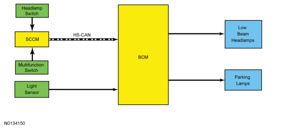
The BCM monitors the light sensor with a voltage signal. The light sensor input to the BCM varies with the ambient light conditions.
When the BCM receives a headlamp switch status message from the SCCM indicating a request for the autolamps, the BCM monitors the light sensor for the ambient light condition. If the BCM determines the ambient light level is dark, the BCM supplies voltage to the exterior lamps.
If the vehicle enters a dark/lighted area (such as when entering/exiting a non-lighted tunnel during the daytime), the transition from light to dark (or dark to light) needs to last 15 seconds before the BCM turns the exterior lamps on or off. This strategy prevents the exterior lamps from unnecessarily flashing on and off.
The BCM reacts quicker under extreme light conditions. If the BCM has detected a very dark condition, the exterior lamps are turned on after 1.5 seconds. If the BCM has detected a very high ambient light level, the exterior lamps are turned off after 4 seconds.
Headlamps On With Wipers On Function
When the headlamp switch is in the autolamps on position, the exterior lamps turn on when the front wipers are on for more than 3 seconds (if wipers are turned on manually) or 30 seconds (if the wipers are on from the rain sensing wiper system). This feature does not activate the exterior lamps during a mist wipe or while the wipers are on to clear washer fluid during a wash condition.
The exterior lamps turn off when the ignition is changed to OFF or ACCESSORY, the headlamp switch is placed in the OFF position, or the front wipers are off for more than 30 seconds (60 seconds if on from the rain sensing wiper system). The exception to this is when the exterior lights are on because of darkness determined by the light sensor.
Component Description
Light Sensor
The BCM sends a voltage signal to the light sensor. The light sensor provides resistance between the voltage signal and ground. The resistance varies depending on the amount of ambient light detected by the light sensor. The brighter the ambient light, the lower the resistance. By varying the resistance, the BCM can determine the amount of ambient light.
Stoplamps
Overview
The stoplamp system consists of:
- Stoplamp switch
- Rear lamp assemblies
- High mounted stoplamp
- BCM
The stoplamp switch is located on the brake pedal assembly. Voltage is supplied to the rear lamps and high mounted stoplamp when the brake pedal is applied.
System Operation
System Diagram
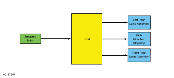
Stoplamps
The BCM monitors the input from the stoplamp switch. When the brake pedal is applied, voltage is routed to the BCM. The BCM then supplies voltage to the stoplamps
The BCM uses a single output to control all of the stoplamps
Component Description
Stoplamp Switch
The stoplamp switch is a normally open switch and is provided voltage at all times. When the brake pedal is applied, the switch closes and routes voltage to the BCM.
Turn Signal and Hazard Lamps
Overview
The turn lamp system consists of:
- Front turn lamps
- Rear lamp assemblies
- Multifunction switch
- SCCM
- FCIM
- BCM
When the multifunction switch is placed in the left or right TURN position, the corresponding turn lamps flash on and off.
The hazard flasher switch is located in the center instrument panel finish panel (integrated into the FCIM ). When the hazard function is active, all the turn lamps flash on and off.
The front turn signal indicator lamps are integrated into the headlamp assemblies.
The rear turn signal indicator lamps operate independently of the stoplamps. (Taurus only)
The rear turn signal indicator lamps and the stoplamps share the same bulb. (Police only)
System Operation
System Diagram
Network Message Chart
BCM Network Input Messages
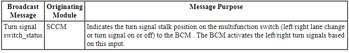
Turn Signals
The SCCM monitors the multifunction switch position. When the multifunction switch is in the left or right turn position, the SCCM sends a turn signal switch status message over the communication network to the BCM indicating a request for the left or right turn signal
When the BCM receives a request for a turn signal, the BCM supplies on/off voltage to the appropriate turn lamps.
The timed on/off cycle for turn lamps is determined by the BCM and is set to flash approximately 80 times per minute if both the front and rear turn signal lamps operate correctly. If an individual turn signal lamp is inoperative, the BCM fast flashes the remaining turn lamp approximately 160 times per minute to indicate a bulb outage to the driver.
The multifunction switch is a momentary contact switch, with 2 detents for the left turn position and 2 detents for the right turn position. When placed in the first detent and released, the corresponding turn signals flash 3 times and turn off. When the multifunction switch is moved to the second detent and released, the turn signal flashes until the steering wheel is turned in the opposite direction (based on input from the steering wheel rotation sensor) or the vehicle travels farther than 3.22 km (2 mi). The SCCM monitors the steering wheel rotation sensor and the multifunction switch input to determine when to cancel the turn signals. The SCCM monitors the distance traveled to determine if the turn signal should be turned off.
The BCM also provides an overload protection of the turn lamp output circuits. When an excessive current draw is detected, the BCM disables the affected turn lamp circuit driver. For additional information, refer to FET in Section 419-10.
Hazard Lamps
The BCM sends a voltage signal to the Front Controls Interface Module (FCIM) to monitor for a hazard lamp function request. When the hazard flasher switch is activated, the voltage signal is routed to ground, indicating a request to activate or deactivate the hazard lamp function
When the BCM receives a request for the hazard lamps, the BCM supplies on/off voltage to all the turn lamps.
The timed on/off cycle for the hazard lamps is approximately 80 times per minute regardless of bulb outage.
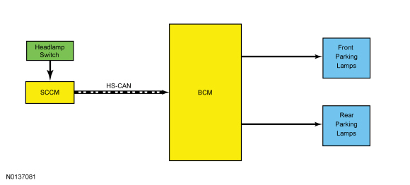
Parking, Rear and License Plate Lamps
Overview
The parking lamp system consists of:
- Front parking lamps
- Front side marker lamps
- Front auxiliary lamps
- Rear decklid lamp assemblies
- Rear lamp assemblies
- License plate lamps
- Headlamp switch
- BCM
- SCCM
The front parking and side marker lamps are integrated into the headlamp assemblies.
The rear parking and side marker lamps are LEDs integrated into the rear lamp assemblies. (Taurus only)
The rear parking and side marker lamps are replaceable bulbs. (Police only)
System Operation
System Diagram
Network Message Chart
BCM Network Input Messages
Parking Lamps
The SCCM monitors the headlamp switch position and sends the headlamp switch status message over the communication network to the BCM to indicate the headlamp switch status (position or a fault with the headlamp switch).
The BCM turns the parking lamps and headlamps on if it loses communication with the SCCM, or if the SCCM detects a fault from the headlamp switch. The head lights will remain on until the battery saver feature times out.
When the BCM receives input requesting the parking lamps on, one circuit provides voltage to all of the front parking lamps and a second circuit provides voltage to all of the rear parking lamps.
Reversing Lamps
Overview
The reverse lamp system consists of:
- Reverse lamps
- Ignition switch (without IA )
- Start/stop switch (with IA )
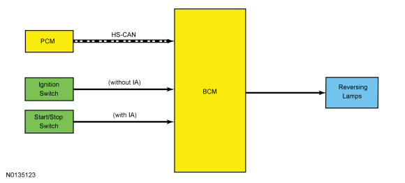
- PCM
- BCM
When the transmission is placed in REVERSE, the reversing lamps are illuminated. The reversing lamps are located within the rear lamp assemblies.
System Operation
System Diagram
Network Message Chart
BCM Network Input Messages
Reversing Lamps
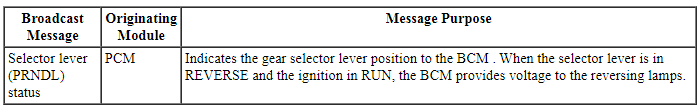
When the transmission is in REVERSE, the PCM sends a selector lever (PRNDL) status message over the communication network to the BCM indicating the transmission is in REVERSE. The BCM provides voltage to the reversing lamps when it receives the message that the transmission is in REVERSE and the ignition is in RUN.
The BCM also provides an overload protection of the reversing lamp output circuits. When an excessive current draw is detected, the BCM disables the affected reversing lamp circuit driver. For additional information, refer to FET in Section 419-10.

 Diagnosis and Testing
Exterior Lighting
DTC Charts
Diagnostics in this manual assume a certain skill level and knowledge of
Ford-specific diagnostic practices. Refer to Diagnostic Methods in Section
100-00 ...
Other materials:
Steering wheel controls
AUDIO CONTROL
SEEK: Press to select the next or
previous stored preset or track.
Press and hold to select the next or
previous frequency or seek through
a track.
MEDIA: Press repeatedly to scroll
through available audio modes.
MUTE: Press to silence the radio.
VOL (Volume): Press to ...
Evaporative Emissions
SPECIFICATIONS
Torque Specifications
DESCRIPTION AND OPERATION
Evaporative Emissions
The EVAP system
consists of the:
EVAP canister purge valve.
EVAP canister.
dust separator and EVAP canister
vent solenoid assembly.
fuel vapor tube assembly (includes ...
General Procedures
Air Conditioning (A/C) Clutch Air Gap Adjustment
Check the A/C clutch air gap at 3 equally spaced places between the
clutch plate and the A/C clutch pulley.
Remove the clutch plate. Add or remove spacers between the clutch plate
hub and the compressor shaft until the clearance is within ...
