Engine
Special Tool(s)
WARNING: Do not smoke, carry lighted tobacco or have an open flame of any type when working on or near any fuel-related component. Highly flammable mixtures are always present and may be ignited. Failure to follow these instructions may result in serious personal injury.
All vehicles
- With the vehicle in NEUTRAL, position it on a hoist. For additional information, refer to Section 100-02.
- Release the fuel system pressure. For additional information, refer to Section 310-00.
- Recover the A/C system. For additional information, refer to Section 412-00.
- Remove the cowl panel grille. For additional information, refer to Section 501-02.
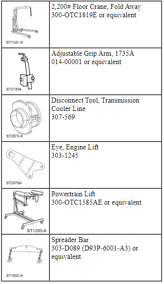
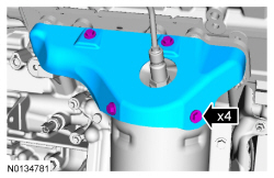
- Remove the 4 nuts and the strut tower brace.
- Remove the engine Air Cleaner (ACL) and ACL outlet pipe. For additional information, refer to Section 303-12.
- Remove the battery tray. For additional information, refer to Section 414-01.
- Remove the nut and disconnect the 2 battery feed cables from the positive battery terminal.
- Remove the retainer and the ground wire cable.
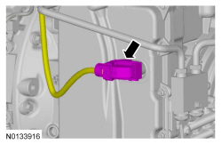
- Disconnect the engine wiring harness electrical connector.

- If equipped, release the 4 retainers and remove the underbody shield.
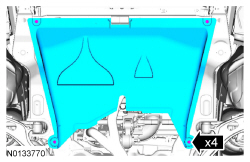
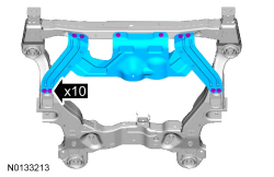
- If equipped, remove the 10 retainers and the skid plate.
- Drain the cooling system. For additional information, refer to Section 303-03.
- Remove the front wheels and tires. For additional information, refer to Section 204-04.
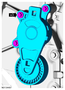
- Remove the 3 pin-type retainers and position aside.

- Remove the accessory drive belt. For additional information, refer to Section 303-05.
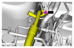
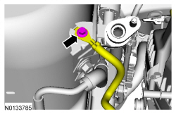
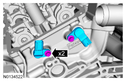
- Remove the nut and disconnect the A/C tube.
- Discard the O-ring seal and gasket seal.
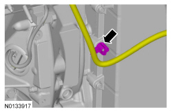
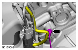
- Disconnect the A/C pressure switch electrical connector.

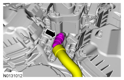
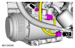
- Remove the nut and the A/C tube from the condenser.
- Discard the O-ring seal and gasket seal.

- Remove the degas bottle. For additional information, refer to Section 303-03.
- Disconnect the degas bottle coolant hose from the engine coolant tube.
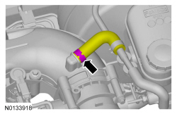
- Disconnect the brake booster vacuum hose from the upper intake manifold.
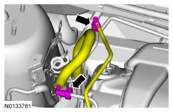
- Disconnect the Evaporative Emission (EVAP) tube and the fuel supply tube quick connect coupling. For additional information, refer to Section 310-00.
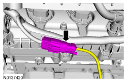
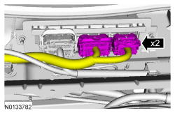
- Disconnect the 2 PCM electrical connectors.

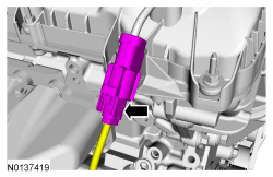
- Disconnect the engine harness electrical connector.
- Detach the wiring harness retainer.

- Remove the engine wiring harness retainer from the bulkhead.
- Push the wiring harness retainer tab in.
- Slide the wiring harness up and out of the bulkhead.
- Remove the bolt and ground wire from the RH shock tower.

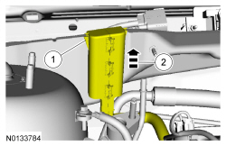
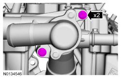
- Disconnect the upper radiator hose, lower radiator hose and 2 heater hoses from the thermostat housing.

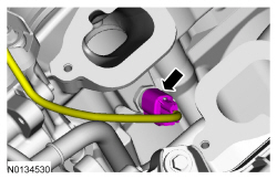
- Disconnect the transaxle control cable from the control lever.

- Disconnect the transaxle control cable from the shift cable bracket and
position aside.
- Detach the wiring harness pin-type retainer from the shift cable bracket.
- If equipped, detach the engine block heater harness from the radiator support.
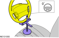
- NOTE: Use a steering wheel holding device (such as Hunter
28-75-1 or equivalent).
Using a suitable holding device, hold the steering wheel in the straight-ahead position.
- NOTICE: Do not allow the intermediate shaft to
rotate while it is disconnected from the gear or damage to the clockspring
may occur. If there is evidence that the intermediate shaft has rotated, the
clockspring must be removed and recentered. For additional information,
refer to Section 501-20B.
NOTE: Index-mark the steering column shaft position to the steering gear for reference during installation.
Remove the bolt and disconnect the steering column shaft from the steering gear.- Discard the bolt.
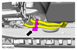
- Remove the exhaust Y-pipe. For additional information, refer to Section 309-00.
All-Wheel Drive (AWD) vehicles
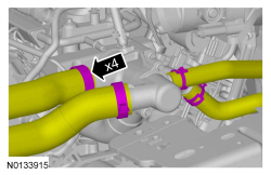
- NOTE: Index-mark the driveshaft for installation.
Remove and discard the 4 bolts and support the driveshaft with a length of mechanic's wire.

All vehicles
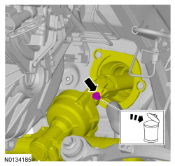
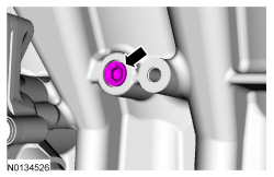
- Remove the drain plug and drain the engine oil.
- Install the drain plug and tighten to 27 Nm (20 lb-ft).
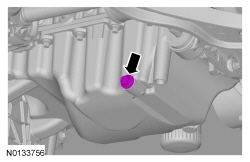
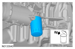
- Remove and discard the engine oil filter.
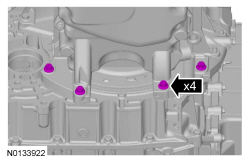
- Remove the 2 fasteners and the inspection cover.
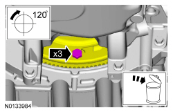
- Remove and discard the 3 torque converter bolts.
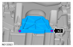
- Remove the 4 oil pan-to-transaxle bolts.
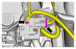
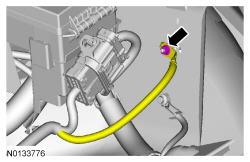
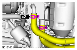
- If equipped, disconnect the 2 oil cooler coolant hoses.

- If equipped, unlatch the cooler hose retainer latch and pry up on the oil cooler hose retainer to release the retainer and remove it from the subframe.

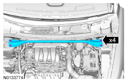
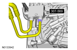
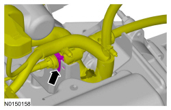
- Remove the 2 secondary latches from the transmission fluid cooler tubes at the transmission fluid cooler thermal bypass valve.

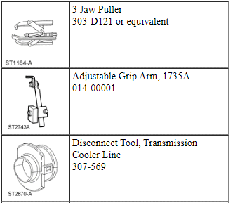
- Using the Transmission Cooler Line Disconnect Tool, disconnect the transmission fluid cooler tubes from the transmission fluid cooler thermal bypass valve.
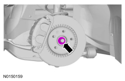
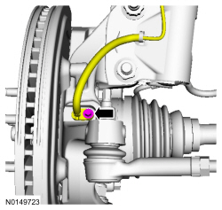
- NOTE: LH shown, RH similar.
Remove the bolt and the wheel speed sensor.

- NOTE: LH shown, RH similar.
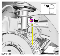
Remove and discard the upper stabilizer link nut.
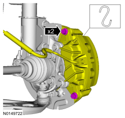
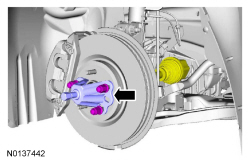
- NOTICE: Do not allow the brake caliper to hang from the brake
flexible hose or damage to the hose may occur.
NOTE: LH shown, RH similar.
Remove the brake caliper guide pin bolts and calipers.- Support the calipers.
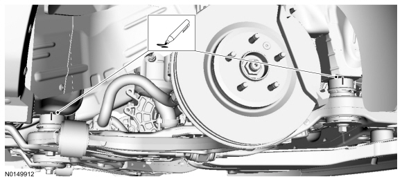
- NOTE: RH shown, LH similar.
Using a wax pencil, mark the relationship of the front and rear subframe to the underbody at the mounting locations on both side.
- NOTE: LH shown, RH similar.
Remove the LH and RH halfshaft nuts.
- Do not discard at this time.
- NOTE: LH shown, RH similar.
Separate the LH and RH halfshaft from the wheel hubs.

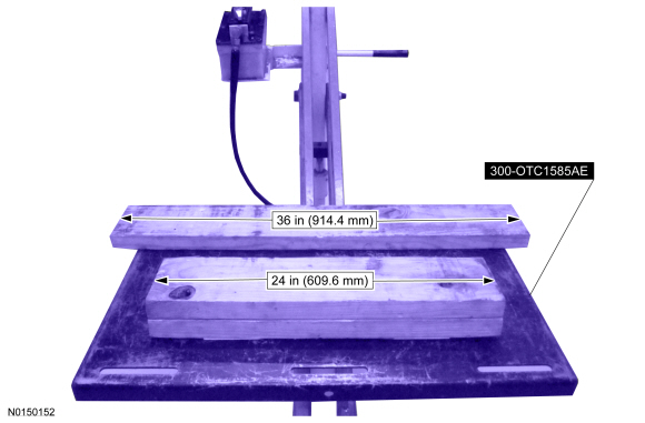
- Position a 2 x 6 board, 36 in (914.4 mm) in length and two 2 x 6 boards
24 in (609.6 mm) in length onto the powertrain lift.
- Position the powertrain lift table with:
- the long board towards the rear of the subframe.
- the short boards under the engine and transmission.
- Position the powertrain lift table with:
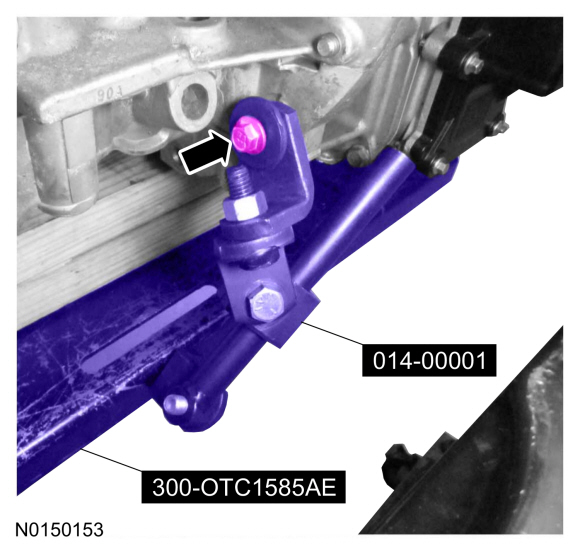
- Install the Adjustable Grip Arm from the powertrain lift table to the LH engine-to-transmission bolt hole.
- Install a ratchet strap from the front of the subframe under the powertrain lift table to the rear of the subframe, to secure the subframe to the powertrain lift table.
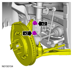
- NOTE: LH shown, RH similar.
NOTE: The halfshafts are not being remove from the transmission.
Remove the strut-to-wheel knuckle nuts and bolts.- Remove the strut from the wheel knuckle and the halfshafts from the wheel knuckle.
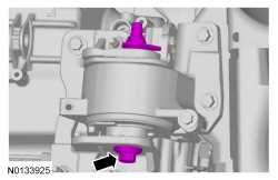
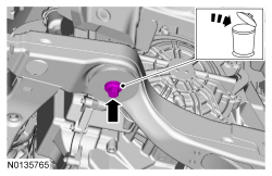
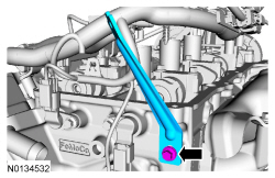
- Remove the transaxle support insulator through bolt and nut.

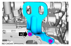
- Remove the bolt, 3 nuts and the transaxle support insulator bracket.

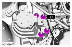
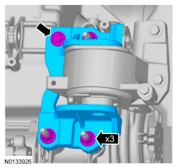
- Remove the 4 engine mount nuts.
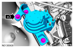
- Remove the 3 bolts and the engine mount.

- NOTE: RH shown, LH similar.
Remove the subframe bracket-to-body bolts.
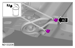
- NOTE: RH shown, LH similar.
Remove the rear subframe bolts and the subframe brackets.
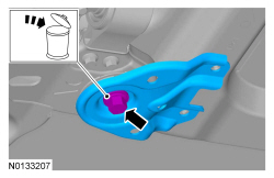
- NOTE: RH shown, LH similar.
Remove the front subframe bolts.

- Lower the subframe and powertrain assembly from the vehicle.
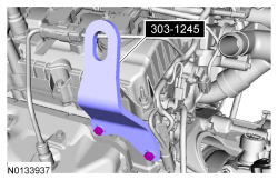
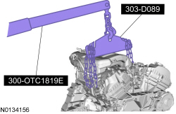
- Install 303-1245 on the LH cylinder head.
- Install the Heavy Duty Floor Crane and Spreader Bar.

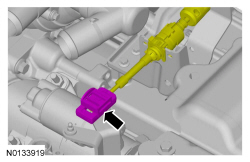
- Remove the starter motor solenoid cover.
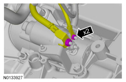
- Remove the 2 nuts and the starter motor wiring terminals.
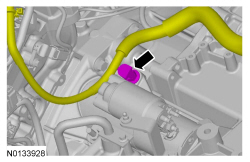
- Disconnect the wiring harness retainer from the starter motor stud bolt.
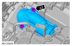
- Remove the bolt, stud bolt and the starter.
- Remove the bolt and the ground wire from the RH cylinder head.

- Disconnect the 2 A/C compressor electrical connectors.
- Detach the A/C wiring harness retainer.

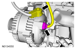
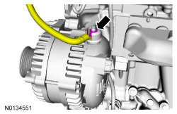
- Disconnect the generator electrical connector and position the generator B+ cable cover aside.

- Remove the nut and disconnect the generator B+ cable.

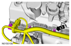
- Detach the 3 wiring harness retainer from the valve cover stud bolt and position the harness on transmission.
- Disconnect the transaxle control electrical connector.
- Detach the transaxle control wire harness retainer from the transaxle stud bolt.
- Disconnect the RH catalyst monitor electrical connector.
- Disconnect the RH Heated Oxygen Sensor (HO2S) electrical connector.
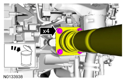
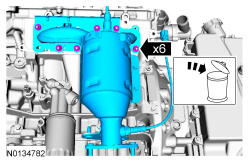
- Remove the 4 nuts and the RH catalytic converter heat shield.

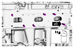
- Remove the 6 nuts and the RH catalytic converter manifold.
- Discard the nuts and RH catalytic converter manifold gasket.
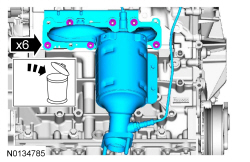
- Remove and discard the 6 RH catalytic converter manifold studs.
AWD vehicles
- Remove the 5 bolts and the Power Transfer Unit (PTU) support bracket.
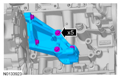
All vehicles
- Remove the Adjustable Grip Arm.

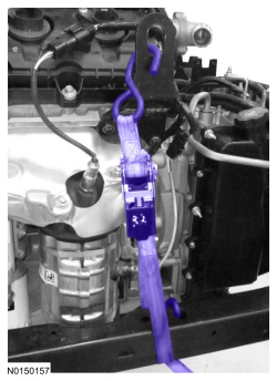
- Remove the ratchet strap from the front of the subframe under the powertrain lift table to the rear of the subframe.
- NOTE: LH shown, RH similar.
Install the ratchet strap from the front subframe to the LH engine lift eye and from the rear of the subframe to the RH engine lift eye.

- Using the Floor Crane and Spreader Bar, remove the powertrain and
subframe as an assembly from the powertrain lift table and set on the
ground.
- Position wood blocks under the engine and transmission.

- NOTE: LH shown, RH similar.
Remove the ratchet strap from the front subframe to the LH engine lift eye and from the rear of the subframe to the RH engine lift eye.
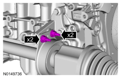
- Remove the 2 intermediate shaft bracket nuts and the 2 studs.
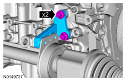
- Remove the 2 bolts and the RH halfshaft support bracket.
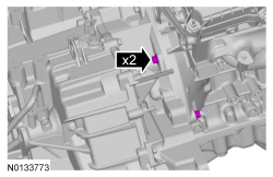
- Remove the 2 engine-to-transaxle bolts.
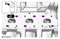
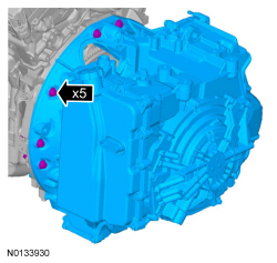
- Remove the 5 transaxle-to-engine bolts.
- Separate the transaxle from the engine.
- Using the Floor Crane and Spreader Bar, remove the engine from the transaxle.
Camshaft
Special Tool(s)
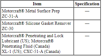
Material
WARNING: Do not smoke, carry lighted tobacco or have an open flame of any type when working on or near any fuel-related component. Highly flammable mixtures are always present and may be ignited. Failure to follow these instructions may result in serious personal injury.
NOTICE: During engine repair procedures, cleanliness is extremely important. Any foreign material, including any material created while cleaning gasket surfaces that enters the oil passages, coolant passages or the oil pan, may cause engine failure.
All vehicles
- With the vehicle in NEUTRAL, position it on a hoist. For additional information, refer to Section 100-02.
- Release the fuel system pressure. For additional information, refer to Section 310-00.
- Recover the A/C system. For additional information, refer to Section 412-00.
- Remove the cowl panel grille. For additional information, refer to Section 501-02.
- Remove the 4 nuts and the strut tower brace.

- Remove the engine Air Cleaner (ACL) and ACL outlet pipe. For additional information, refer to Section 303-12.
- Remove the battery tray. For additional information, refer to Section 414-01.
- Remove the nut and disconnect the 2 battery feed cables from the positive battery terminal.

- Remove the retainer and the ground wire cable.

- Disconnect the engine wiring harness electrical connector.
- If equipped, release the 4 retainers and remove the underbody shield.

- If equipped, remove the 10 retainers and the skid plate.

- Drain the cooling system. For additional information, refer to Section 303-03.
- Remove the front wheels and tires. For additional information, refer to Section 204-04.
- Remove the 3 pin-type retainers and position aside.
- Remove the accessory drive belt. For additional information, refer to Section 303-05.
- Remove the nut and disconnect the A/C tube.
- Discard the O-ring seal and gasket seal.

- Disconnect the A/C pressure switch electrical connector.

- Remove the nut and the A/C tube from the condenser.
- Discard the O-ring seal and gasket seal.
- Remove the degas bottle. For additional information, refer to Section 303-03.
- Disconnect the degas bottle coolant hose from the engine coolant tube.

- Disconnect the brake booster vacuum hose from the upper intake manifold.

- Disconnect the Evaporative Emission (EVAP) tube and the fuel supply tube quick connect coupling. For additional information, refer to Section 310-00.

- Disconnect the 2 PCM electrical connectors.
- Disconnect the engine harness electrical connector.
- Detach the wiring harness retainer.
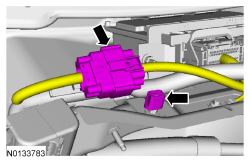
- Remove the engine wiring harness retainer from the bulkhead.
- Push the wiring harness retainer tab in.
- Slide the wiring harness up and out of the bulkhead.

- Remove the bolt and ground wire from the RH shock tower.
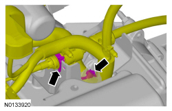
- Disconnect the upper radiator hose, lower radiator hose and 2 heater hoses from the thermostat housing.
- Disconnect the transaxle control cable from the control lever.
- Disconnect the transaxle control cable from the shift cable bracket and position aside.
- If equipped, detach the engine block heater harness from the radiator support.
- NOTE: Use a steering wheel holding device (such as Hunter
28-75-1 or equivalent).
Using a suitable holding device, hold the steering wheel in the straight-ahead position.

- NOTICE: Do not allow the intermediate shaft to
rotate while it is disconnected from the gear or damage to the clockspring
may occur. If there is evidence that the intermediate shaft has rotated, the
clockspring must be removed and recentered. For additional information,
refer to Section 501-20B.
NOTE: Index-mark the steering column shaft position to the steering gear for reference during installation.
Remove the bolt and disconnect the steering column shaft from the steering gear.- Discard the bolt.

- Remove the exhaust Y-pipe. For additional information, refer to Section 309-00.
All-Wheel Drive (AWD) vehicles
- NOTE: Index-mark the driveshaft for installation.
Remove and discard the 4 bolts and support the driveshaft with a length of mechanic's wire.
All vehicles
- Remove the drain plug and drain the engine oil.
- Install the drain plug and tighten to 27 Nm (20 lb-ft).

- Remove and discard the engine oil filter.

- If equipped, disconnect the 2 oil cooler coolant hoses.
- If equipped, unlatch the cooler hose retainer latch and pry up on the oil cooler hose retainer to release the retainer and remove it from the subframe.
- Remove the 2 secondary latches from the transmission fluid cooler tubes at the transmission fluid cooler thermal bypass valve.
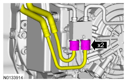
- Using the Transmission Cooler Line Disconnect Tool, disconnect the transmission fluid cooler tubes from the transmission fluid cooler thermal bypass valve.

- NOTE: LH shown, RH similar.
Remove the bolt and the wheel speed sensor.
- NOTE: LH shown, RH similar.
Remove and discard the upper stabilizer link nut.

- NOTICE: Do not allow the brake caliper to hang from the brake
flexible hose or damage to the hose may occur.
NOTE: LH shown, RH similar.
Remove the brake caliper guide pin bolts and calipers.- Support the calipers.

- NOTE: RH shown, LH similar.
Using a wax pencil, mark the relationship of the front and rear subframe to the underbody at the mounting locations on both side.

- NOTE: LH shown, RH similar.
Remove the LH and RH halfshaft nuts.
- Do not discard at this time.

- NOTE: LH shown, RH similar.
Separate the LH and RH halfshaft from the wheel hubs.
- Position a 2 x 6 board, 36 in (914.4 mm) in length and two 2 x 6 boards
24 in (609.6 mm) in length onto the powertrain lift.
- Position the powertrain lift table with:
- the long board towards the rear of the subframe.
- the short boards under the engine and transmission.
- Position the powertrain lift table with:

- Install the Adjustable Grip Arm from the powertrain lift table to the LH engine-to-transmission bolt hole.

- Install a ratchet strap from the front of the subframe under the powertrain lift table to the rear of the subframe, to secure the subframe to the powertrain lift table.
- NOTE: LH shown, RH similar.
NOTE: The halfshafts are not being remove from the transmission.
Remove the strut-to-wheel knuckle nuts and bolts.- Remove the strut from the wheel knuckle and the halfshafts from the wheel knuckle.

- Remove the transaxle support insulator through bolt and nut.
- Remove the bolt, 3 nuts and the transaxle support insulator bracket.
- Remove the 4 engine mount nuts.

- Remove the 3 bolts and the engine mount.
- NOTE: RH shown, LH similar.
Remove the subframe bracket-to-body bolts.

- NOTE: RH shown, LH similar.
Remove the rear subframe bolts and the subframe brackets.

- NOTE: RH shown, LH similar.
Remove the front subframe bolts.
- Lower the subframe and powertrain assembly from the vehicle.
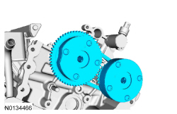
- Remove the 3 bolts and the accessory drive belt tensioner.
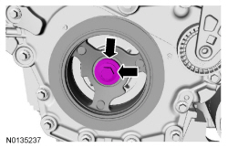
- Remove the crankshaft pulley bolt and washer.
- Discard the bolt.
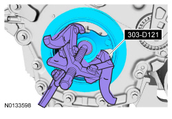
- Using the 3 Jaw Puller, remove the crankshaft pulley.
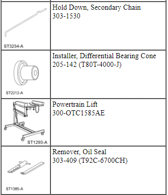
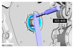
- Using the Oil Seal Remover, remove and discard the crankshaft front seal.
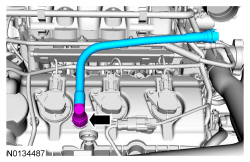
- Remove the crankcase vent tube. For additional information, refer to the quick connect coupling in Section 310-00.
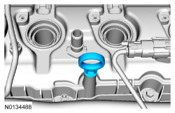
- Remove the oil level indicator.
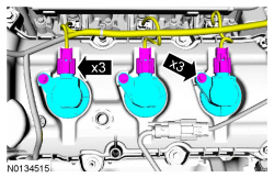
- Disconnect the 3 LH coil-on-plug electrical connectors and remove the 3 bolts and the 3 LH-coil-on-plugs.
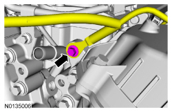
- Remove the ground wire bolt from the engine front cover.
- Remove the engine wiring harness from the LH valve cover.
- Disconnect the 2 Variable Camshaft Timing (VCT) oil control solenoid electrical connectors.
- Detach and disconnect the LH Heated Oxygen Sensor (HO2S) electrical connector.
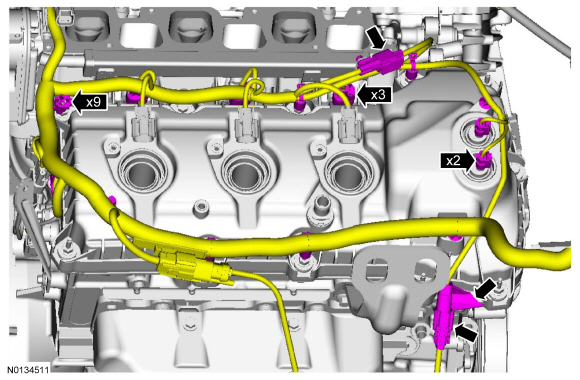
- Disconnect the 3 fuel injector electrical connectors.
- Detach the 11 wiring harness retainers from the LH valve cover and stud bolts and position the harness aside.
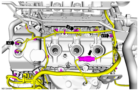
- NOTICE: While removing the valve cover do not apply excessive
force to the Variable Camshaft Timing (VCT) oil control solenoid or damage
may occur.
NOTICE: If the Variable Camshaft Timing (VCT) oil control solenoid sticks to the VCT seal, carefully wiggle the valve cover until the bond breaks free or damage to the VCT seal and VCT oil control solenoid may occur.
Loosen the 4 bolts and 7 stud bolts.- Remove the LH valve cover.
- Discard the gasket.
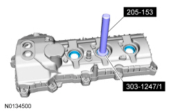
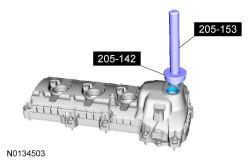
- Inspect the VCT solenoid seals. Remove any damaged seals.
- Using the Differential Bearing Cone Installer and Handle, remove and discard the seal(s).
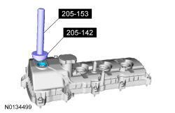
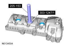
- Inspect the spark plug tube seals. Remove any damaged seals.
- Using the Spark Plug Tube Seal Remover and Handle, remove and discard the seal(s).
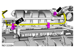
- Disconnect the Evaporative Emission (EVAP) canister vent solenoid and
throttle body electrical connectors.
- Detach the wiring harness pin-type retainer from the upper intake manifold.
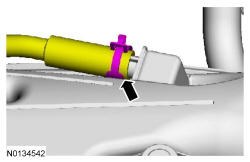
- Disconnect the EVAP vapor tube from the EVAP canister vent solenoid. For
additional information, refer to Section 310-00.
- Detach the EVAP vapor tube from the 2 retainers.
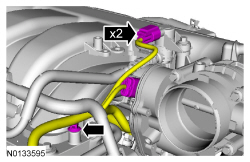
- Disconnect the crankcase ventilation hose from the upper intake manifold.
- Detach the 2 coolant tube retainers from the upper intake manifold.
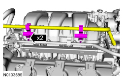
- Remove the upper intake manifold support bracket bolt.
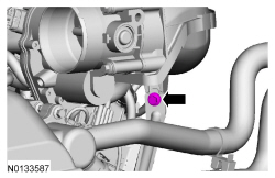
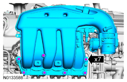
- Remove the 7 bolts and the upper intake manifold.
- Remove and discard the gasket.
- Clean and inspect all of the sealing surfaces of the upper and lower intake manifold.
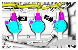
- Disconnect the 3 RH coil-on-plug electrical connectors and remove the 3 bolts and the 3 RH -coil-on-plugs.
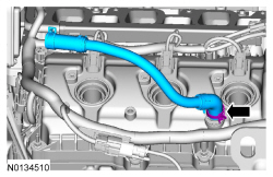
- Remove the PCV crankcase vent tube.
- Remove the engine wiring harness from the RH valve cover.
- Disconnect the 2 Variable Camshaft Timing (VCT) oil control solenoid electrical connectors.
- Detach and disconnect the RH Catalyst Monitor Sensor (CMS) electrical connector.
- Disconnect the 3 fuel injector electrical connectors.
- Disconnect the Cylinder Head Temperature (CHT) sensor wiring harness jumper electrical connector.
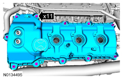
- Detach the 9 wiring harness retainers from the RH valve cover and stud bolts and position the harness aside.
- NOTICE: While removing the valve cover do not apply excessive
force to the Variable Camshaft Timing (VCT) oil control solenoid or damage
may occur.
NOTICE: If the Variable Camshaft Timing (VCT) oil control solenoid sticks to the VCT seal, carefully wiggle the valve cover until the bond breaks free or damage to the VCT seal and VCT oil control solenoid may occur.
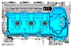
Loosen the 2 bolts and 9 stud bolts.- Remove the RH valve cover.
- Discard the gasket.
- Inspect the 2 VCT solenoid seals. Remove any damaged seals.
- Using the Differential Bearing Cone Installer and Handle, remove the seal(s).
- Inspect the spark plug tube seals. Remove any damaged seals.
- Using the VCT Spark Plug Tube Seal Remover and Handle, remove the seal(s).
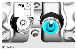
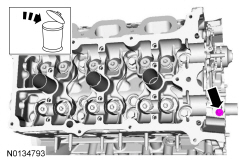
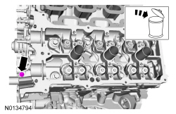
- Clean the valve covers, cylinder heads and engine front cover sealing surfaces with metal surface prep.
- Remove the generator nut and stud.
- Loosen the bolt and position the generator aside.
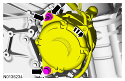
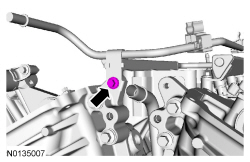
- Remove the fuel supply tube-to-engine front cover bolt.
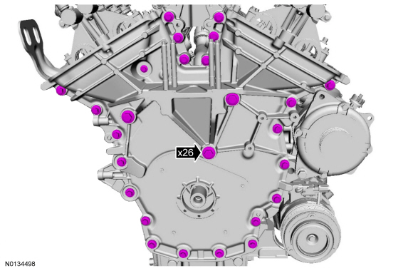
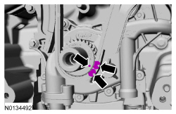
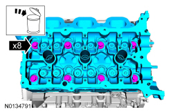
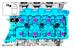
- Remove the 26 front cover bolts.
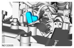
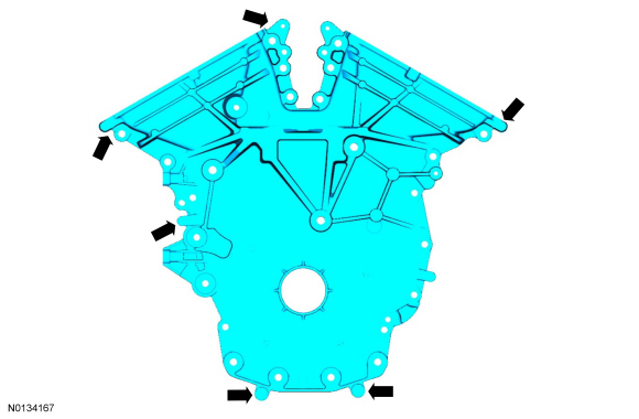
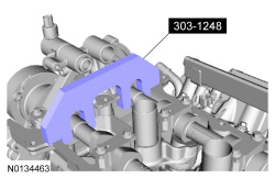
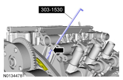
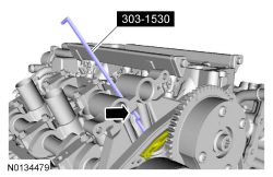
- Using a suitable pry tool, locate the 5 pry pads shown and pry the engine front cover loose and remove.
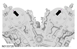
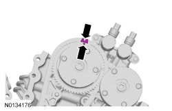
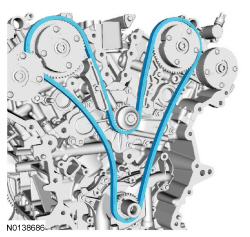
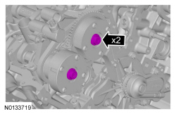
- Rotate the crankshaft clockwise and align the timing marks on the intake Variable Camshaft Timing (VCT) assemblies as shown.
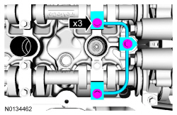
- Remove the 3 bolts and the LH valve train oil tube.
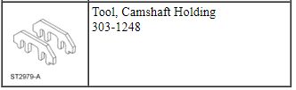
- NOTE: The Camshaft Holding Tool will hold the camshafts in the
Top Dead Center (TDC) position.
Install the Camshaft Holding Tool onto the flats of the LH camshafts.
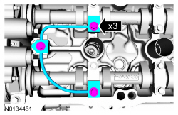
- Remove the 3 bolts and the RH valve train oil tube.
- NOTE: The Camshaft Holding Tool will hold the camshafts in
the TDC position.
Install the Camshaft Holding Tool onto the flats of the RH camshafts.

NOTE: The following 3 steps are for primary timing chains that the colored links are not visible.
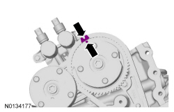
- Mark the timing chain link that aligns with the timing mark on the LH intake VCT assembly as shown.
- Mark the timing chain link that aligns with the timing mark on the RH intake VCT assembly as shown.
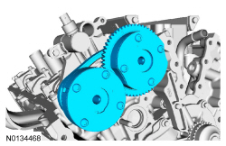
- NOTE: The crankshaft sprocket timing mark should be between the 2
colored links.
Mark the 2 timing chain links that align with the timing mark on the crankshaft sprocket as shown.
- Remove the 2 bolts and the primary timing chain tensioner.
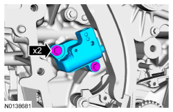
- Remove the primary timing chain tensioner arm.
- Remove the 2 bolts and the lower LH primary timing chain guide.
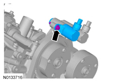
- NOTE: Removal of the VCT oil control solenoid will aid in the
removal of the primary timing chain.
NOTE: A slight twisting motion will aid in the removal of the VCT oil control solenoid.
NOTE: Keep the VCT oil control solenoid clean of dirt and debris.
Remove the bolt and the LH intake VCT oil control solenoid.
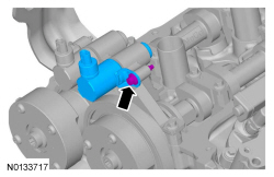
- NOTE: Removal of the VCT oil control solenoid will aid in the
removal of the primary timing chain.
NOTE: A slight twisting motion will aid in the removal of the VCT oil control solenoid.
NOTE: Keep the VCT oil control solenoid clean of dirt and debris.
Remove the bolt and the RH intake VCT oil control solenoid.
- Remove the primary timing chain.
LH camshafts
- NOTE: The 2 VCT oil control solenoids are removed for clarity.
NOTE: The Secondary Chain Hold Down is inserted through a hole in the top of the mega cap.
Compress the LH secondary timing chain tensioner and install the Secondary Chain Hold Down in the hole on the rear of the secondary timing chain tensioner guide and let it hold against the mega cap to retain the tensioner in the collapsed position.
- Remove and discard the 2 LH VCT assembly bolts.
- Remove the 2 LH VCT assemblies and secondary timing chain.
- NOTE: When the Camshaft Holding Tool is removed, valve spring
pressure may rotate the LH camshafts approximately 3 degrees to a neutral
position.
Remove the Camshaft Holding Tool from the LH camshafts.

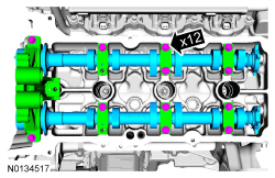
- NOTE: Cylinder head camshaft bearing caps are numbered to verify
that they are assembled in their original positions.
NOTE: Mark the exhaust and intake camshafts for installation into their original locations.
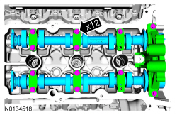
Remove the 12 bolts, 6 camshaft caps, mega cap and the LH camshafts.
RH camshafts
- NOTE: The 2 VCT oil control solenoids are removed for clarity.
NOTE: The Secondary Chain Hold Down is inserted through a hole in the top of the mega cap.
Compress the RH secondary timing chain tensioner and install the Secondary Chain Hold Down in the hole on the rear of the secondary timing chain tensioner guide and let it hold against the mega cap to retain the tensioner in the collapsed position.
- Remove and discard the 2 RH VCT assembly bolts.
- Remove the 2 RH VCT assemblies and secondary timing chain.
- NOTE: When the Camshaft Holding Tool is removed, valve spring
pressure may rotate the RH camshafts approximately 3 degrees to a neutral
position.
Remove the Camshaft Holding Tool from the RH camshafts.
- NOTE: Cylinder head camshaft bearing caps are numbered to verify
that they are assembled in their original positions.
NOTE: Mark the exhaust and intake camshafts for installation into their original locations.
Remove the 12 bolts, 6 camshaft caps, mega cap and the RH camshafts.
Valve Tappets
NOTICE: During engine repair procedures, cleanliness is extremely important. Any foreign material, including any material created while cleaning gasket surfaces that enters the oil passages, coolant passages or the oil pan, may cause engine failure.
- Depending on the valve tappets being serviced, remove the LH and/or the RH camshafts. For additional information, refer to Camshaft in this section.
- NOTE: If the components are to be reinstalled, they must be
installed in the same positions. Mark the components for installation into
their original locations.
Remove the valve tappets from the cylinder head.

Valve Spring, Retainer and Seal
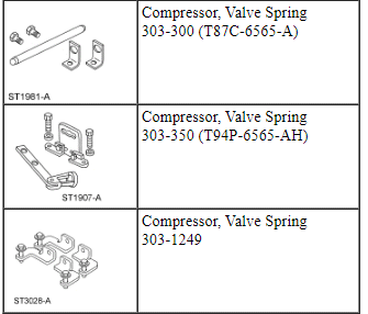
Special Tool(s)
NOTICE: During engine repair procedures, cleanliness is extremely important. Any foreign material, including any material created while cleaning gasket surfaces that enters the oil passages, coolant passages or the oil pan, may cause engine failure.
- Remove the valve tappets from the cylinder being serviced. For additional information, refer to Valve Tappets in this section.
- NOTICE: If air pressure has forced the piston to the bottom of
the cylinder, any loss of air pressure will allow the valve to fall into the
cylinder. If air pressure must be removed, support the valve prior to
removal or engine damage may occur.
NOTE: If the components are to be reinstalled, they must be installed in the same positions. Mark the components for installation into their original locations.
NOTE: If a valve drops into the cylinder, remove the cylinder head. For additional information, refer to Cylinder Head - RH or Cylinder Head - LH in this section.
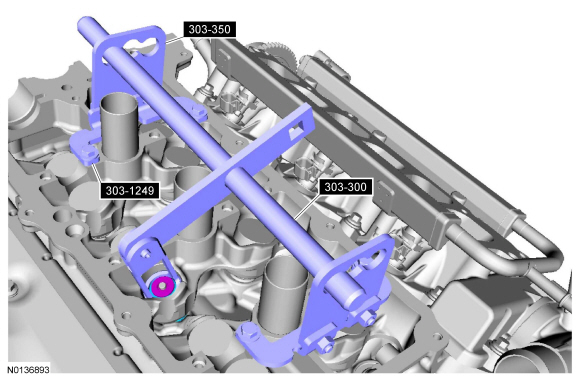
Rotate the crankshaft clockwise until the piston for the valve being serviced is at the top of its stroke. Pressurize the cylinder using compressed air.
- Using the Valve Spring Compressors, remove the keys, retainer and spring.
- Remove and discard the valve stem seal.
Cylinder Head - RH
Material
NOTICE: During engine repair procedures, cleanliness is extremely important. Any foreign material, including any material created while cleaning gasket surfaces that enters the oil passages, coolant passages or the oil pan, can cause engine failure.
NOTE: If the cylinder head is replaced, a new secondary timing chain tensioner will need to be installed.
- Remove the RH camshafts. For additional information, refer to Camshaft in this section.
- If equipped, remove the block heater heat shield.
- If equipped, disconnect the block heater electrical connector.
- Remove the block heater wiring harness from the engine.
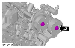
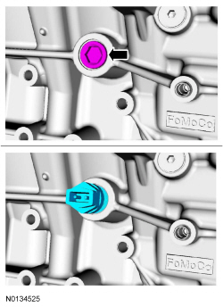
- Disconnect the 2 RH Camshaft Position Camshaft Position (CMP) sensor electrical connectors.
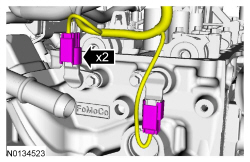
- Remove the 2 bolts and the 2 CMP sensors.

- Remove the bolt and the ground cable from the RH cylinder.
- Remove the LH cylinder block drain plug.
- Allow coolant to drain from the cylinder block.

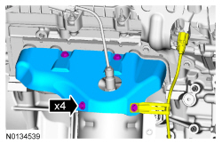
- Remove the 4 bolts and the RH catalytic converter heat shield.
- Remove the 6 nuts and the RH catalytic converter manifold.
- Discard the nuts and catalytic converter gasket.

- Clean and inspect the RH catalytic converter manifold. For additional information, refer to Section 303-00.
- Remove and discard the 6 RH exhaust manifold studs.

- Remove the RH cylinder block drain plug or, if equipped, the block
heater.
- Allow coolant to drain from the cylinder block.

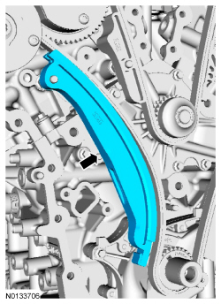
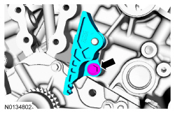
- NOTICE: Do not use power tools to remove the bolt or damage to
the RH primary timing chain guide may occur.
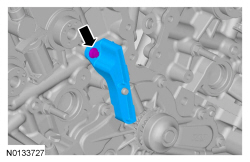
Remove the bolt and the RH primary timing chain guide.
- Remove the 2 bolts and the engine lifting eye.
- NOTE: Index-mark the location of the bracket on the cylinder head
for installation.
Remove the bolt and the upper intake manifold bracket.
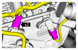
- Remove the 2 thermostat housing-to-lower intake manifold bolts.
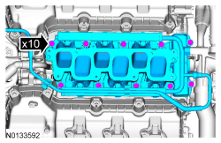
- NOTICE: If the engine is repaired or replaced because of upper
engine failure, typically including valve or piston damage, check the intake
manifold for metal debris. If metal debris is found, install a new intake
manifold. Failure to follow these instructions can result in engine damage.
Remove the 10 bolts and the lower intake manifold.
- Remove and discard the intake manifold and thermostat housing gaskets.
- Clean and inspect all sealing surfaces.

- Disconnect and remove the CHT sensor jumper harness.
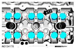
- NOTE: If the components are to be reinstalled, they must be
installed in the same positions. Mark the components for installation into
their original locations.
Remove the valve tappets from the cylinder head.

- Inspect the valve tappets. For additional information, refer to Section 303-00.
- Remove and discard the M6 bolt.
- NOTICE: Place clean shop towels over exposed engine cavities.
Carefully remove the towels so foreign material is not dropped into the
engine. Any foreign material (including any material created while cleaning
gasket surfaces) that enters the oil passages or the oil pan, may cause
engine failure.
NOTICE: Aluminum surfaces are soft and can be scratched easily. Never place the cylinder head gasket surface, unprotected, on a bench surface.
NOTE: The cylinder head bolts must be discarded and new bolts must be installed. They are tighten-to-yield designed and cannot be reused.
Remove and discard the 8 bolts from the cylinder head.- Remove the cylinder head.
- Discard the cylinder head gasket.
- NOTICE: Do not use metal scrapers, wire brushes, power
abrasive discs or other abrasive means to clean the sealing surfaces. These
tools cause scratches and gouges that make leak paths. Use a plastic
scraping tool to remove all traces of the head gasket.
NOTE: Observe all warnings or cautions and follow all application directions contained on the packaging of the silicone gasket remover and the metal surface prep.
NOTE: If there is no residual gasket material present, metal surface prep can be used to clean and prepare the surfaces.
Clean the cylinder head-to-cylinder block mating surfaces of both the cylinder heads and the cylinder block in the following sequence.- Remove any large deposits of silicone or gasket material with a plastic scraper.
- Apply silicone gasket remover, following package directions, and allow to set for several minutes.
- Remove the silicone gasket remover with a plastic scraper. A second application of silicone gasket remover may be required if residual traces of silicone or gasket material remain.
- Apply metal surface prep, following package directions, to remove any remaining traces of oil or coolant and to prepare the surfaces to bond with the new gasket. Do not attempt to make the metal shiny. Some staining of the metal surfaces is normal.
- Support the cylinder head on a bench with the head gasket side up. Check the cylinder head distortion and the cylinder block distortion. For additional information, refer to Section 303-00.
Cylinder Head - LH
Material
NOTICE: During engine repair procedures, cleanliness is extremely important. Any foreign material, including any material created while cleaning gasket surfaces that enters the oil passages, coolant passages or the oil pan, can cause engine failure.
- Remove the LH camshafts. For additional information, refer to Camshaft in this section.
- If equipped, remove the block heater heat shield.

- If equipped, disconnect the block heater electrical connector.
- Remove the block heater wiring harness from the engine.

- Disconnect the 2 LH Camshaft Position (CMP) sensor electrical connectors.
- Remove the 2 bolts and the 2 LH CMP sensors.
- Remove the wiring harness retainer from the rear of the LH cylinder head.
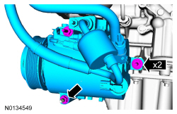
- Disconnect the 2 A/C compressor electrical connectors.
- Detach the A/C wiring harness retainer.
- Remove the nut, 2 stud bolts and the A/C compressor.
- Disconnect the generator electrical connector and position the generator B+ cable cover aside.
- Remove the nut and disconnect the generator B+ cable.
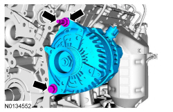
- Remove the nut, bolt and the generator.
- Remove the generator stud.
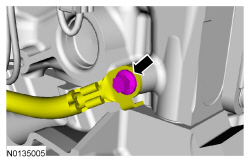
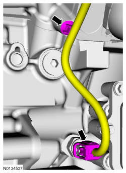
- Disconnect the Engine Oil Pressure (EOP) switch electrical connector and the wiring harness pin-type retainer.
- Remove the 3 bolts and the LH exhaust heat shield.
- Remove the 6 nuts and the LH catalytic converter.
- Discard the nuts and the gasket.
- Clean and inspect the catalytic converter flange. For additional information, refer to exhaust manifold cleaning and inspection in Section 303-00.
- Remove and discard the 6 LH exhaust manifold studs.
- Remove the LH cylinder block drain plug.
- Allow coolant to drain from the cylinder block.
- Remove the RH cylinder block drain plug or if equipped, the block
heater.
- Allow coolant to drain from the cylinder block.
- Remove the 2 thermostat housing-to-lower intake manifold bolts.

- NOTICE: If the engine is repaired or replaced because of upper
engine failure, typically including valve or piston damage, check the intake
manifold for metal debris. If metal debris is found, install a new intake
manifold. Failure to follow these instructions can result in engine damage.
Remove the 10 bolts and the lower intake manifold.
- Remove and discard the intake manifold and thermostat housing gaskets.
- Clean and inspect all sealing surfaces.
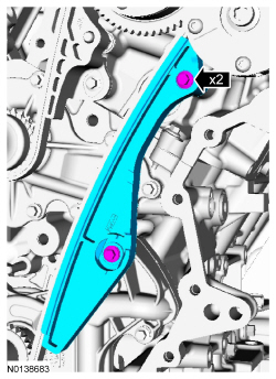
- NOTICE: Do not use power tools to remove the bolt or damage to
the upper LH primary timing chain guide may occur.
Remove the bolt and the upper LH primary timing chain guide.
- NOTE: If the components are to be reinstalled, they must be
installed in the same positions. Mark the components for installation into
their original locations.
Remove the valve tappets from the cylinder head.
- Inspect the valve tappets. For additional information, refer to Section 303-00.
- Remove and discard the M6 bolt.
- NOTICE: Place clean shop towels over exposed engine cavities.
Carefully remove the towels so foreign material is not dropped into the
engine. Any foreign material (including any material created while cleaning
gasket surfaces) that enters the oil passages or the oil pan, may cause
engine failure.
NOTICE: Aluminum surfaces are soft and can be scratched easily. Never place the cylinder head gasket surface, unprotected, on a bench surface.
NOTE: The cylinder head bolts must be discarded and new bolts must be installed. They are tighten-to-yield designed and cannot be reused.
Remove and discard the 8 bolts from the cylinder head.- Remove the cylinder head.
- Discard the cylinder head gasket.
- NOTICE: Do not use metal scrapers, wire brushes, power
abrasive discs or other abrasive means to clean the sealing surfaces. These
tools cause scratches and gouges that make leak paths. Use a plastic
scraping tool to remove all traces of the head gasket.
NOTE: Observe all warnings or cautions and follow all application directions contained on the packaging of the silicone gasket remover and the metal surface prep.
NOTE: If there is no residual gasket material present, metal surface prep can be used to clean and prepare the surfaces.
Clean the cylinder head-to-cylinder block mating surfaces of both the cylinder heads and the cylinder block in the following sequence.- Remove any large deposits of silicone or gasket material with a plastic scraper.
- Apply silicone gasket remover, following package directions, and allow to set for several minutes.
- Remove the silicone gasket remover with a plastic scraper. A second application of silicone gasket remover may be required if residual traces of silicone or gasket material remain.
- Apply metal surface prep, following package directions, to remove any remaining traces of oil or coolant and to prepare the surfaces to bond with the new gasket. Do not attempt to make the metal shiny. Some staining of the metal surfaces is normal.
- Support the cylinder head on a bench with the head gasket side up. Check the cylinder head distortion and the cylinder block distortion. For additional information, refer to Section 303-00.
 In-Vehicle Repair
Upper Intake Manifold
Removal
NOTICE: If the engine is repaired or replaced because of upper
engine failure, typically including valve or piston damage, check the intake
manifold for metal debr ...
 Disassembly
Engine
Special Tool(s)
Material
NOTICE: During engine repair procedures, cleanliness is extremely
important. Any foreign material, including any material created while cleaning
gasket surfa ...
Other materials:
MyFord Touch® (If Equipped)
INTRODUCTION
WARNING: Driving while distracted can result in loss of vehicle
control, crash and injury. We strongly recommend that you use
extreme caution when using any device that may take your focus off
the road. Your primary responsibility is the safe operation of your
vehicle. We recommend ...
Vehicle storage
If you plan on storing your vehicle for an extended period of time
(30 days or more), read the following maintenance recommendations to
make sure your vehicle stays in good operating condition.
All motor vehicles and their components were engineered and tested for
reliable, regular driving. Lo ...
Automatic high beam control
The system will automatically turn on your high beams if it is dark
enough and no other traffic is present. When it detects an approaching
vehicleŌĆÖs headlights, a preceding vehicleŌĆÖs tail lamps or street lighting, the
system will turn off the high beams (low beams remain on) before they
dist ...
