SPECIFICATIONS
Torque Specifications
a Refer to the procedure in this section.
DESCRIPTION AND OPERATION
Rear Suspension
The rear suspension consists of the following components:
- Lower arm(s)
- Shock absorber(s)
- Spring(s)
- Stabilizer bar(s)
- Stabilizer bar link(s)
- Trailing arm(s)
- Toe link(s)
- Upper arm(s)
- Wheel bearing and wheel hub(s)
- Wheel knuckle(s)
The rear suspension utilizes an independent short/long arm design. This suspension system incorporates a separate wheel knuckle for each wheel and allows the wheels to react to road imperfections independent of each other. This independent action offers improved isolation from the effects of jounce and rebound.
REMOVAL AND INSTALLATION
Wheel Bearing and Wheel Hub
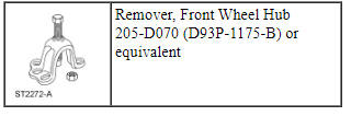
Special Tool(s)
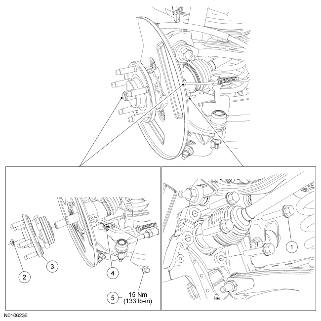
NOTE: All-Wheel Drive (AWD) shown, Front Wheel Drive (FWD) vehicles similar.
Removal
All vehicles
NOTICE: Suspension fasteners are critical parts because they affect performance of vital components and systems and their failure may result in major service expense. New parts must be installed with the same part numbers or equivalent part, if replacement is necessary. Do not use a replacement part of lesser quality or substitute design. Torque values must be used as specified during reassembly to make sure of correct retention of these parts.
- Remove the brake disc. For additional information, refer to Section 206-04.
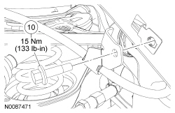
- Remove the wheel speed sensor bolt and position the sensor aside.
All-Wheel Drive (AWD) vehicles
- NOTE: Do not discard the nut at this time.
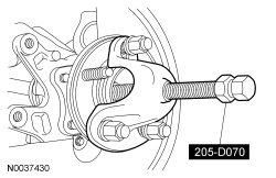
Remove the wheel hub nut.
- Using the Front Wheel Hub Remover, separate the halfshaft from the wheel hub.
All vehicles
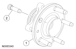
- Remove the 4 bolts and the wheel bearing and wheel hub.
- Discard the bolts.
- NOTICE: The wheel knuckle bore must be clean enough to allow
the wheel bearing and wheel hub to seat completely by hand. Do not press or
draw the wheel hub and bearing into place or damage to the bearing may
occur.
NOTICE: Make sure the wheel hub-to-knuckle mating surfaces are clean and free of any adhesive. Failure to clean adhesive from both surfaces may cause bearing damage.
Using a clean shop towel, clean the wheel knuckle-to-mating surfaces and inspect the knuckle bearing bore.- If the wheel knuckle is cracked or damaged, install a new wheel knuckle.
Installation
All vehicles
- Install the wheel bearing and wheel hub assembly.
- Install the 4 new wheel bearing and wheel hub bolts.
- Tighten the bolts to 133 Nm (98 lb-ft) in a cross-pattern.
- Install the brake disc. For additional information, refer to Section 206-04.
- Position the wheel speed sensor and install the bolt.
- Tighten to 15 Nm (133 lb-in).
AWD vehicles
- NOTICE: Do not tighten the rear wheel hub nut with the vehicle
on the ground. The nut must be tightened to specification before the vehicle
is lowered to the ground. Wheel bearing damage will occur if the wheel
bearing is loaded with the weight of the vehicle applied.
NOTE: Apply the brake to keep the halfshaft from rotating.
Position the halfshaft in the hub and use the previously removed wheel hub nut to seat the halfshaft.- Tighten the nut to 350 Nm (258 lb-ft).
- Remove and discard the nut.
- NOTICE: Install and tighten the new wheel hub nut to
specification within 5 minutes of starting it on the threads. Always install
a new wheel hub nut after loosening or when not tightening within the
specified time or damage to the components may occur.
Install a new wheel hub nut.
- Tighten the nut to 350 Nm (258 lb-ft).
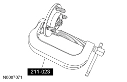
Wheel Studs
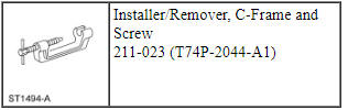
Special Tool(s)
Removal
NOTICE: Suspension fasteners are critical parts because they affect performance of vital components and systems and their failure may result in major service expense. New parts must be installed with the same part numbers or equivalent part, if replacement is necessary. Do not use a replacement part of lesser quality or substitute design. Torque values must be used as specified during reassembly to make sure of correct retention of these parts.
- Remove the wheel bearing and wheel hub. For additional information, refer to Wheel Bearing and Wheel Hub in this section.
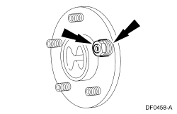
- Using the C-Frame and Screw Installer/Remover, remove the wheel stud.
Installation
NOTICE: Do not use air tools to install the wheel stud. The serrations in the hub flange can be stripped.
- NOTE: Make sure to use washers that have an ID that is larger
than the OD of the wheel stud serrations. Use enough washers (approximately
4) to allow the wheel stud to seat against the hub flange.
Position the wheel stud in the axle flange, making sure that the serrations are aligned with those made by the original wheel stud.
- Position washers and a wheel nut on the wheel stud and tighten the wheel nut until the stud is seated against the hub flange.
- Remove the wheel nut and washers.
- Discard the wheel nut.
- Install the wheel bearing and wheel hub. For additional information, refer to Wheel Bearing and Wheel Hub in this section.
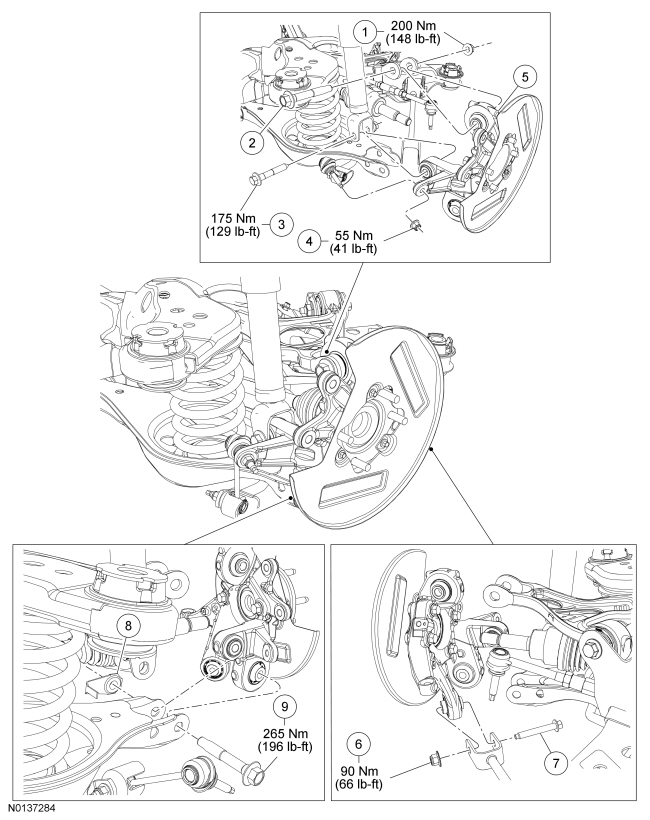
Upper Arm
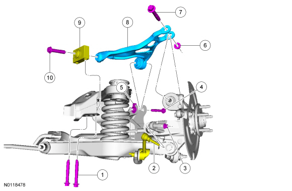
NOTE: Brake disc has been removed for clarity.
Removal
NOTICE: Suspension fasteners are critical parts because they affect performance of vital components and systems and their failure may result in major service expense. New parts must be installed with the same part numbers or equivalent part, if replacement is necessary. Do not use a replacement part of lesser quality or substitute design. Torque values must be used as specified during reassembly to make sure of correct retention of these parts.
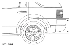
- Measure the distance from the center of the wheel hub to the lip of the fender with the vehicle in a level, static ground position (curb height).

- Remove the rear wheels and tires. For additional information, refer to Section 204-04.
- Remove LH and RH parking brake cable bracket bolts.
- NOTICE: Do not allow the brake caliper to hang from the brake
flexible hose or damage to the hose may occur.
Remove the 4 brake caliper anchor plate bolts and position the LH and RH brake caliper and anchor plate assemblies aside.
- Support the brake caliper and anchor plate assemblies using mechanic's wire.
- Position screw-type jackstands under the LH and RH wheel knuckles.
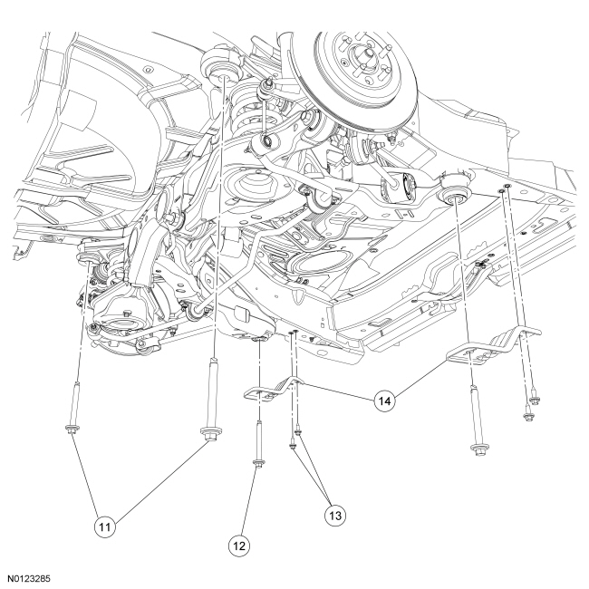
- Remove and discard the upper arm-to-knuckle bolt and nut.
- Remove and discard the 2 upper arm-to-subframe rearward bolts.
NOTE: Use the hex-holding feature to prevent the stabilizer bar link stud from turning while removing or installing the nut.
- Remove and discard the LH and RH stabilizer bar link upper nuts and disconnect the links from the stabilizer bar.
- Remove and discard the LH and RH lower shock bolts.
- Remove and discard the 4 subframe bracket bolts.
- Remove and discard the 2 subframe forward bolts and remove the 2 subframe brackets.
- Remove and discard the 2 subframe rearward bolts and lower the subframe enough to allow removal of the upper arm forward bolt.
- Remove and discard the upper arm-to-subframe forward bolt and nut.
- Remove the upper arm.
- If service to the upper arm rearward bushing is required, remove the
upper arm bushing bolt and remove the upper arm bushing.
- Discard the bolt.
Installation
NOTE: Before tightening the shock absorber lower bolts and upper arm nut and bolts, use a jackstand to raise the rear suspension until the distance between the center of the hub and the lip of the fender is equal to the measurement taken in the Removal procedure (curb height).
- If removed, install the upper arm bushing onto the upper arm in the
following sequence.
- With the upper arm positioned so the top side is facing up and the upper arm bushing is positioned with the TOP OF PART facing up and the ARM TO THIS SIDE arrow is pointing toward the upper arm. Install the upper arm bushing.
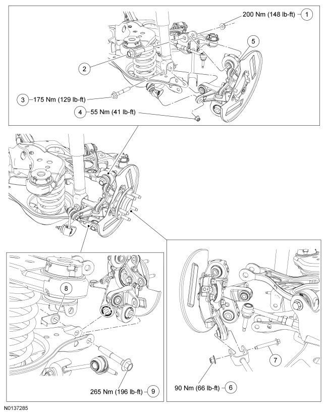
- Install a new upper arm rearward bushing bolt and tighten to 200 Nm (148 lb-ft).
- Position the upper arm and loosely install the new upper arm-to-subframe forward bolt and nut.
- Raise the subframe and install 2 new subframe rearward bolts.
- Tighten to 200 Nm (148 lb-ft).
- Position the 2 subframe brackets and install 4 new subframe bracket
bolts.
- Tighten to 55 Nm (41 lb-ft).
- Install 2 new subframe forward bolts.
- Tighten to 150 Nm (111 lb-ft).
- Loosely install new LH and RH shock absorber lower bolts.
NOTE: Use the hex-holding feature to prevent the stabilizer bar link stud from turning while removing or installing the nut.
- Connect the LH and RH stabilizer bar links to the stabilizer bar and
install the new nuts.
- Tighten to 55 Nm (41 lb-ft).
- Loosely install 2 new upper arm-to-subframe rearward bolts.
- Loosely install a new upper arm-to-knuckle bolt and nut.
- Position the LH and RH brake caliper and anchor plate assemblies and
install the 4 anchor plate bolts.
- Tighten to 103 Nm (76 lb-ft).
- Install LH and RH parking brake cable bracket bolts.
- Tighten to 15 Nm (133 lb-in).
- Using the screw-type jackstand, raise the rear suspension until the distance between the center of the hub and the lip of the fender is equal to the measurement taken in the removal procedure (curb height).
- Tighten the upper arm-to-subframe forward bolt to 150 Nm (111 lb-ft).
- Tighten the LH and RH shock absorber lower bolts to 175 Nm (129 lb-ft).
- Tighten the 2 upper arm-to-subframe rearward bolts to 150 Nm (111 lb-ft).
- NOTE: A slotted upper arm allows for the rear suspension camber
to be adjusted by pushing inward or pulling outward on the wheel knuckle
while tightening the upper arm-to-wheel knuckle nut.
With the wheel knuckle pushed inward for maximum negative camber, tighten the upper arm-to-wheel knuckle nut to 200 Nm (148 lb-ft).
- Remove the 2 jackstands.
- Install the rear wheels and tires. For additional information, refer to Section 204-04.
- Check and, if necessary, adjust the rear camber. For additional information, refer to Section 204-00.
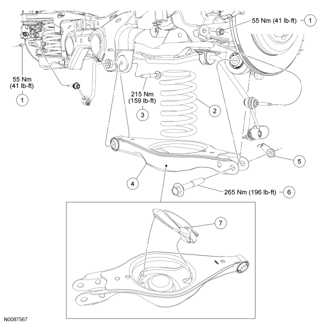
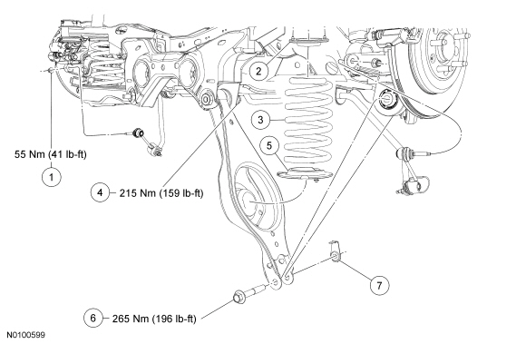
Lower Arm
NOTE: Front Wheel Drive (FWD) vehicle shown, All-Wheel Drive (AWD) vehicle similar.
Removal
NOTICE: Suspension fasteners are critical parts because they affect performance of vital components and systems and their failure may result in major service expense. New parts must be installed with the same part numbers or equivalent part, if replacement is necessary. Do not use a replacement part of lesser quality or substitute design. Torque values must be used as specified during reassembly to make sure of correct retention of these parts.
- Measure the distance from the center of the wheel hub to the lip of the fender with the vehicle in a level, static ground position (curb height).

- Remove the wheel and tire. For additional information, refer to Section 204-04.
- NOTE: Use the hex-holding feature to prevent the stabilizer bar
link stud from turning while removing the nut.
Remove both stabilizer bar link upper nuts and disconnect the links from the wheel knuckle.
- Discard the nuts.
- Position a screw-type jackstand under the lower arm.
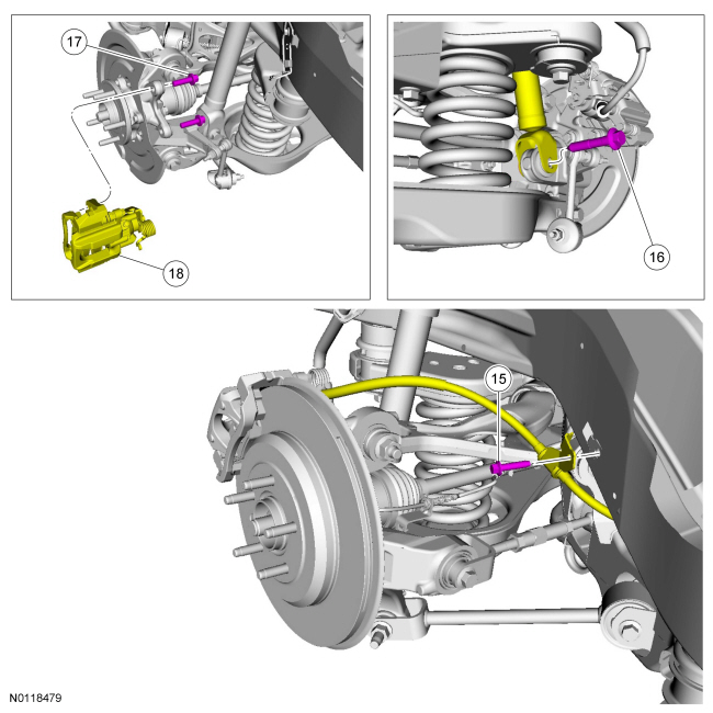
- Remove and discard the lower arm-to-knuckle bolt and nut.
- NOTE: Do not remove the lower arm inner bolt at this time.
Loosen the lower arm inner bolt.
- Lower the jackstand and remove the spring.
- Remove the lower arm inner bolt and lower arm.
- Discard the bolt.
Installation
NOTE: Before tightening the lower arm bolts, use a jackstand to raise the rear suspension until the distance between the center of the hub and the lip of the fender is equal to the measurement taken in the Removal procedure (curb height).
- Position the lower arm and loosely install the new lower arm inner bolt.
- NOTE: Make sure the lower spring seat is properly positioned in
the lower arm.
Install the spring and position the screw-type jackstand under the lower arm.

- NOTE: Do not tighten the lower arm nut at this time.
Raise the jackstand and loosely install the new lower arm-to-knuckle bolt and nut.
- Using the jackstand, raise the rear suspension until the distance between the center of the hub and the lip of the fender is equal to the measurement taken in the Removal procedure (curb height).
- Tighten the lower arm-to-subframe bolt to 215 Nm (159 lb-ft).
- Tighten the lower arm-to-knuckle bolt to 265 Nm (196 lb-ft).
- NOTE: Use the hex-holding feature to prevent the stabilizer bar
link stud from turning while removing the nut.
Position the stabilizer bar links and install 2 new stabilizer bar link upper nuts.
- Tighten to 55 Nm (41 lb-ft).
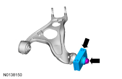
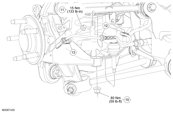
Toe Link
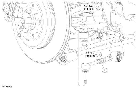
Removal and Installation
NOTICE: Suspension fasteners are critical parts because they affect performance of vital components and systems and their failure may result in major service expense. New parts must be installed with the same part numbers or equivalent part, if replacement is necessary. Do not use a replacement part of lesser quality or substitute design. Torque values must be used as specified during reassembly to make sure of correct retention of these parts.
- Measure the distance from the center of the wheel hub to the lip of the fender with the vehicle in a level, static ground position (curb height).

- Remove the wheel and tire. For additional information, refer to Section 204-04.
- Use a jackstand to raise the rear suspension until the distance between the center of the hub and the lip of the fender is equal to the measurement taken in Step 1 of the procedure (curb height).
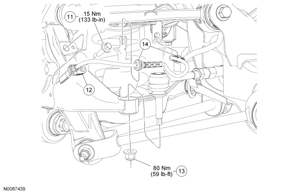
- Remove and discard the toe link-to-wheel knuckle nut.
- To install, tighten the new nut to 80 Nm (59 lb-ft).
- Remove and discard the toe link-to-subframe bolt.
- To install, tighten the new bolt to 150 Nm (111 lb-ft).
- To install, reverse the removal procedure.
- Check and, if necessary, adjust the rear toe. For additional information, refer to Section 204-00.
Trailing Arm
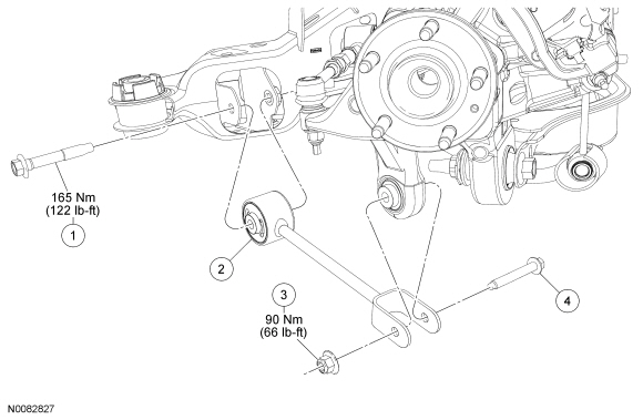
Removal and Installation
NOTICE: Suspension fasteners are critical parts because they affect performance of vital components and systems and their failure may result in major service expense. New parts must be installed with the same part numbers or equivalent part, if replacement is necessary. Do not use a replacement part of lesser quality or substitute design. Torque values must be used as specified during reassembly to make sure of correct retention of these parts.
- Measure the distance from the center of the wheel hub to the lip of the fender with the vehicle in a level, static ground position (curb height).
- Remove the wheel and tire. For additional information, refer to Section 204-04.
- Use a jackstand to raise the rear suspension until the distance between the center of the hub and the lip of the fender is equal to the measurement taken in Step 1 of the procedure (curb height).
- Remove and discard the trailing arm-to-knuckle nut and bolt.
- To install, tighten the new nut to 90 Nm (66 lb-ft).
- Remove and discard the trailing arm-to-subframe bolt.
- To install, tighten the new bolt to 165 Nm (122 lb-ft).
- To install, reverse the removal procedure.
Stabilizer Bar
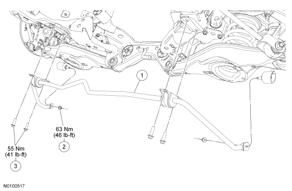
Removal and Installation
NOTICE: Suspension fasteners are critical parts because they affect performance of vital components and systems and their failure may result in major service expense. New parts must be installed with the same part numbers or equivalent part, if replacement is necessary. Do not use a replacement part of lesser quality or substitute design. Torque values must be used as specified during reassembly to make sure of correct retention of these parts.
NOTE: Use the hex-holding feature to prevent the stabilizer bar link stud from turning while removing or installing the nut.
- With the vehicle in NEUTRAL, position it on a hoist. For additional information, refer to Section 100-02.
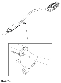
- NOTICE: Do not damage or tear the isolators during removal.
Support the exhaust system with a suitable jackstand. Using soapy water, disconnect the 2 muffler and tail pipe isolators and lower the exhaust approximately 50.8 mm (2 in).
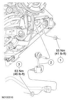
- Remove and discard the 2 stabilizer bar link lower nuts.
- To install, tighten the new nuts to 63 Nm (46 lb-ft).
- Remove and discard the 4 stabilizer bar bracket bolts.
- To install, tighten the new bolts to 55 Nm (41 lb-ft).
- Remove the stabilizer bar.
- To install, reverse the removal procedure.
Stabilizer Bar Link
Removal and Installation
NOTICE: Suspension fasteners are critical parts because they affect performance of vital components and systems and their failure may result in major service expense. New parts must be installed with the same part numbers or equivalent part, if replacement is necessary. Do not use a replacement part of lesser quality or substitute design. Torque values must be used as specified during reassembly to make sure of correct retention of these parts.
NOTE: Use the hex-holding feature to prevent the stabilizer bar link stud from turning while removing or installing the nut.
- Remove and discard the stabilizer bar link lower nut.
- To install, tighten the new nut to 63 Nm (46 lb-ft).
- Remove the stabilizer bar link upper nut and stabilizer bar link.
- Discard the nut.
- To install, tighten the new nut to 55 Nm (41 lb-ft).
- To install, reverse the removal procedure.
Wheel Knuckle - Front Wheel Drive (FWD)
Removal
NOTICE: Suspension fasteners are critical parts because they affect performance of vital components and systems and their failure may result in major service expense. New parts must be installed with the same part numbers or equivalent part, if replacement is necessary. Do not use a replacement part of lesser quality or substitute design. Torque values must be used as specified during reassembly to make sure of correct retention of these parts.
- Measure the distance from the center of the wheel hub to the lip of the fender with the vehicle in a level, static ground position (curb height).

- Remove the wheel and tire. For additional information, refer to Section 204-04.
- Remove the brake disc. For additional information, refer to Section 206-04.
- Using a suitable jackstand, support the lower arm.
- Remove and discard the trailing arm-to-wheel knuckle nut and bolt.
- NOTE: Use the hex-holding feature to prevent the stabilizer bar
link stud from turning while removing the nut.
Remove and discard the stabilizer bar link upper nut and disconnect the link.
- Remove and discard the shock absorber lower bolt and disconnect the shock absorber.
- Remove the wheel speed sensor bolt, disconnect the harness and position the sensor and harness assembly aside.
- Remove and discard the toe link-to-knuckle nut.
- Remove and discard the upper arm-to-wheel knuckle nut and bolt and disconnect the upper arm from the knuckle.
- Remove and discard the lower arm-to-wheel knuckle nut and bolt.
- Lower the jackstand, slide the knuckle off the toe link and remove the knuckle.
Installation
NOTE: Before tightening any suspension bushing fasteners, use a jackstand to raise the rear suspension until the distance between the center of the hub and the lip of the fender is equal to the measurement taken in the removal procedure (curb height).
- Position the wheel knuckle onto the toe link and loosely install a new lower arm-to-wheel knuckle nut and bolt.
- Loosely install a new toe link-to-knuckle nut.
- Position the wheel speed sensor harness and install the wheel speed
sensor and bolt.
- Tighten to 15 Nm (133 lb-in).
- Connect the shock absorber to the knuckle and loosely install a new shock absorber lower bolt.
- Connect the stabilizer bar link and install a new stabilizer bar link
upper nut.
- Tighten to 55 Nm (41 lb-ft).
- NOTE: Use the hex-holding feature to prevent the stabilizer bar
link stud from turning while removing or installing the nut.
Loosely install a new trailing arm-to-wheel knuckle nut and bolt.
- Loosely install a new upper arm-to-wheel knuckle nut and bolt.
- Position a suitable jackstand under the lower control arm at the shock and spring assembly attachment point and raise the rear suspension until the distance between the center of the hub and the lip of the fender is equal to the measurement taken in Step 1 of the procedure (curb height).
- NOTE: A slotted upper arm allows for the rear suspension camber
to be adjusted by pushing inward or pulling outward on the wheel knuckle
while tightening the upper arm-to-wheel knuckle nut.
With the wheel knuckle pushed inward for maximum negative camber, tighten the upper arm-to-wheel knuckle nut to 200 Nm (148 lb-ft).
- Tighten the lower arm-to-wheel knuckle bolt to 265 Nm (196 lb-ft).
- Tighten the shock absorber lower bolt to 175 Nm (129 lb-ft).
- Tighten the trailing arm-to-wheel knuckle nut to 90 Nm (66 lb-ft).
- Tighten the toe link-to-knuckle nut to 80 Nm (59 lb-ft).
- Install the brake disc. For additional information, refer to Section 206-04.
- Install the wheel and tire. For additional information, refer to Section 204-04.
- Check and if necessary, adjust the rear toe. For additional information, refer to Section 204-00.
Wheel Knuckle - All Wheel Drive (AWD)
Removal
NOTICE: Suspension fasteners are critical parts because they affect performance of vital components and systems and their failure may result in major service expense. New parts must be installed with the same part numbers or equivalent part, if replacement is necessary. Do not use a replacement part of lesser quality or substitute design. Torque values must be used as specified during reassembly to make sure of correct retention of these parts.
- Measure the distance from the center of the wheel hub to the lip of the fender with the vehicle in a level, static ground position (curb height).

- Remove the wheel bearing and wheel hub. For additional information, refer to Wheel Bearing and Wheel Hub in this section.
- Using a suitable jackstand, support the lower arm.
- Remove and discard the trailing arm-to-wheel knuckle nut and bolt.
- NOTE: Use the hex-holding feature to prevent the stabilizer bar
link stud from turning while removing or installing the nut.
Remove and discard the stabilizer bar link upper nut and disconnect the link.
- Remove and discard the shock absorber lower bolt and disconnect the shock absorber from the knuckle bracket.
- Remove and discard the toe link-to-knuckle nut.
- Remove and discard the upper arm-to-wheel knuckle nut and bolt and disconnect the upper arm from the knuckle.
- Remove and discard the lower arm-to-wheel knuckle nut and bolt.
- Lower the jackstand, slide the knuckle off the toe link and remove the knuckle.
- If necessary, remove the 3 brake disc shield bolts and remove the shield.
Installation
NOTE: Before tightening suspension bushing fasteners, use a jackstand to raise the rear suspension until the distance between the center of the hub and the lip of the fender is equal to the measurement taken in the removal procedure (curb height).
- If removed, install the brake disc shield.
- Tighten the 3 bolts to 15 Nm (133 lb-in).
- Position the wheel knuckle onto the toe link and loosely install a new lower arm-to-wheel knuckle nut and bolt.
- Loosely install a new toe link-to-knuckle nut.
- Connect the shock absorber to the knuckle and loosely install a new shock absorber lower bolt.
- NOTE: Use the hex-holding feature to prevent the stabilizer bar
link stud from turning while removing or installing the nut.
Connect the stabilizer bar link and install a new stabilizer bar link upper nut.
- Tighten to 55 Nm (41 lb-ft).
- Loosely install a new trailing arm-to-wheel knuckle nut and bolt.
- Raise the jackstand and loosely install a new upper arm-to-wheel knuckle nut and bolt.
- Position a suitable jackstand under the lower control arm at the shock and spring assembly attachment point and raise the rear suspension until the distance between the center of the hub and the lip of the fender is equal to the measurement taken in Step 1 of the procedure (curb height).
- NOTE: A slotted upper arm allows for the rear suspension camber
to be adjusted by pushing inward or pulling outward on the wheel knuckle
while tightening the upper arm-to-wheel knuckle nut.
With the wheel knuckle pushed inward for maximum negative camber, tighten the upper arm-to-wheel knuckle nut to 200 Nm (148 lb-ft).
- Tighten the lower arm-to-wheel knuckle bolt to 265 Nm (196 lb-ft).
- Tighten the shock absorber lower bolt to 175 Nm (129 lb-ft).
- Tighten the trailing arm-to-wheel knuckle nut to 90 Nm (66 lb-ft).
- Tighten the toe link-to-wheel knuckle nut to 80 Nm (59 lb-ft).
- Install the wheel bearing and wheel hub. For additional information, refer to Wheel Bearing and Wheel Hub in this section.
- Check and if necessary, adjust the rear toe. For additional information, refer to Section 204-00.
Spring
Removal
NOTICE: Suspension fasteners are critical parts because they affect performance of vital components and systems and their failure may result in major service expense. New parts must be installed with the same part numbers or equivalent part, if replacement is necessary. Do not use a replacement part of lesser quality or substitute design. Torque values must be used as specified during reassembly to make sure of correct retention of these parts.
- Measure the distance from the center of the wheel hub to the lip of the fender with the vehicle in a level, static ground position (curb height).

- Remove the wheel and tire. For additional information, refer to Section 204-04.
- NOTE: Use the hex-holding feature to prevent the stabilizer bar
link studs from turning while removing the nuts.
Remove and discard the 2 stabilizer bar link upper nuts.
- Position the stabilizer bar away from the lower arm.
- Using a suitable jackstand, support the lower arm.
- Loosen the lower arm-to-subframe bolt.
- Remove and discard the lower arm-to wheel knuckle bolt.
- Lower the jackstand and remove the spring.
- NOTE: Make sure the lower spring seat is properly positioned in
the lower arm.
Inspect the upper and lower spring seats for damage and, if necessary, install new spring seats.
Installation
NOTE: Before tightening the lower arm bolts, use a jackstand to raise the rear suspension until the distance between the center of the hub and the lip of the fender is equal to the measurement taken in the Removal procedure (curb height).
- Install the spring and position the jackstand under the lower arm.
- Raise the jackstand and loosely install a new lower arm-to-wheel knuckle bolt.
- NOTE: Use the hex-holding feature to prevent the stabilizer bar
link studs from turning while installing the nuts.
Position the stabilizer bar and links and install 2 new stabilizer bar link upper nuts.
- Tighten to 55 Nm (41 lb-ft).
- Using the jackstand, raise the rear suspension until the distance between the center of the hub and the lip of the fender is equal to the measurement taken in the Removal procedure (curb height).
- Tighten the lower arm-to-wheel knuckle bolt to 265 Nm (196 lb-ft).
- Tighten the lower arm-to-subframe bolt to 215 Nm (159 lb-ft).
- Install the wheel and tire. For additional information, refer to Section 204-04.
Shock Absorber
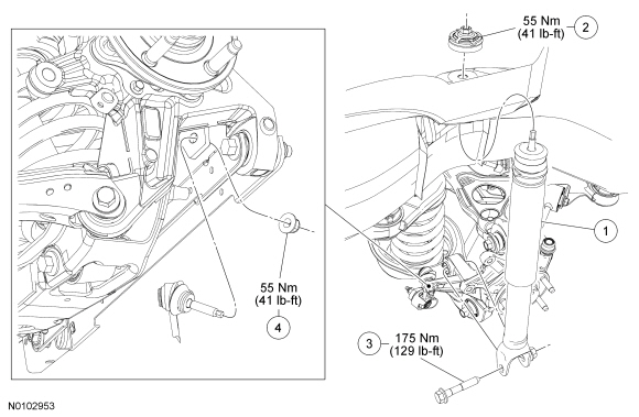
Removal and Installation
NOTICE: Suspension fasteners are critical parts because they affect performance of vital components and systems and their failure may result in major service expense. New parts must be installed with the same part numbers or equivalent part, if replacement is necessary. Do not use a replacement part of lesser quality or substitute design. Torque values must be used as specified during reassembly to make sure of correct retention of these parts.
NOTE: Use the hex-holding feature on the stock rod nut to prevent the shock rod from rotating when removing or installing the shock rod nut.
- Pull back the luggage compartment side trim panel to gain access to the shock absorber upper nut.
- NOTICE: Do not use power tools. Tighten using hand tools only.
Failure to do so will result in shock absorber damage and/or Noise,
Vibration and Harshness (NVH) concerns.
Remove and discard the shock absorber upper mount nut.
- To install, tighten the new nut to 55 Nm (41 lb-ft).
- Remove the wheel and tire. For additional information, refer to Section 204-04.
- NOTE: Use the hex-holding feature to prevent the stabilizer bar
link stud from turning while removing or installing the nut.
Remove and discard the stabilizer bar link upper nut and disconnect the link from the wheel knuckle.
- To install, tighten the new nut to 55 Nm (41 lb-ft).
- Remove and discard the shock absorber lower bolt and remove the shock
absorber.
- To install, tighten the new bolt to 175 Nm (129 lb-ft).
- To install, reverse the removal procedure.
 Front Suspension
SPECIFICATIONS
Material
Torque Specifications
a Refer to the procedure in this section.
DESCRIPTION AND OPERATION
Front Suspension
The front suspension consists of the following components:
W ...
 Wheels and Tires
...
Other materials:
Specifications, Description and Operation
SPECIFICATIONS
Material
a 6F50 transmission.
b 6F55 transmission.
Torque Specifications
a Refer to the procedure in this section.
General Specifications
Solenoid Operation Chart
a Turns on
above 8 km/h (5 mph).
b Turns off above 8 km/h (5 mph).
NC = Normally closed
NH = ...
Specifications, Description and Operation
SPECIFICATIONS
General Specifications
a Manifold gauge set pressures may vary slightly depending on the
distance between the service gauge port valve and the A/C pressure relief valve,
the A/C cycling switch or the pressure cutoff switch location.
Material
DESCRIPTION AND OPERATION
Climate ...
Rear Drive Axle/Differential
SPECIFICATIONS
Material
Torque Specifications
DESCRIPTION AND OPERATION
Rear Drive Axle and Differential
The rear drive axle consists of the following components:
Dished circular flange
Full-time Active Torque Coupling (ATC)
Aluminum housing with steel housing cover
Matched ring and pinion ...
