SPECIFICATIONS
Torque Specifications
DESCRIPTION AND OPERATION
Lighting, Siren and Speaker System
Spotlamps
Overview
The spotlamps provide an exterior illumination source that can be directed by an interior control handle to illuminate the desired object.
System Operation
The LH and RH spotlamps are provided battery voltage from BJB fuse 81 (20A) and are grounded to the vehicle body through the spotlamp mount.
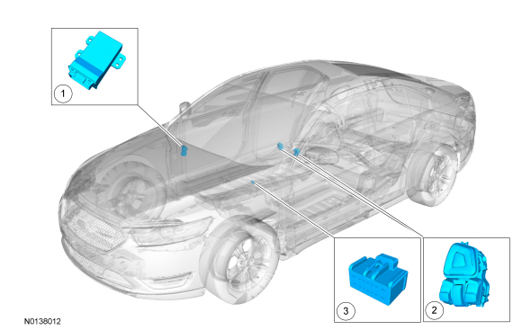
Flashing LEDs
Component Location
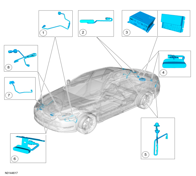
Overview
The flashing LEDs are used to visually alert individuals to the vehicles presence. The number and placement of flashing LEDs varies based on the police package ordered.
System Operation
System Diagram
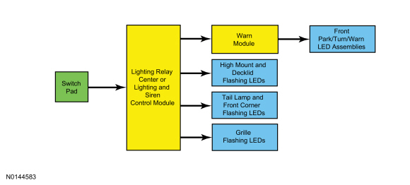
Flashing LEDs
The flashing LEDs are turned on and off by zones. There are 4 zones for the flashing LEDs:
- Front park/turn/warn LED assemblies
- Grille flashing LEDs (if equipped)
- Tail lamp and front corner flashing LEDs (if equipped)
- High mount and decklid flashing LEDs (if equipped)
LED Flash Patterns
The LED flash patterns are preset from the factory and can be changed in 2 groups. Refer to LED Flash Pattern Programming.
The 2 groups are:
- Front park/turn/warn, grille, front corner and tail lamp flashing LEDs
- High mount and decklid flashing LEDs
When a flashing LED is replaced, the flash pattern of the replacement LED may be different than the rest in the group. Refer to LED Flash Pattern Programming.
Flashing LEDs Synchronization
The flashing LEDs are synchronized in up to 4 groups:
- Front park/turn/warn LED assemblies
- Grille flashing LEDs (if equipped)
- Tail lamp and front corner flashing LEDs (if equipped)
- High mount and decklid flashing LEDs (if equipped)
The flashing LED assemblies contain a module that controls the flash pattern and synchronizes the flashing LED with the other flashing LEDs in the group.
Flashing LED Controls
The flashing LEDs are driven and controlled by the following:
- Lighting relay center or lighting and siren control module
- Controls the grille, front corner, tail lamp, high mount and decklid flashing LEDs
- Warn module
- Controls the front/park/turn/warn LED assemblies
Component Description
Front Park/Turn/Warn LED Assembly
The front park/turn/warn assemblies are mounted in the headlamp assemblies. The standard park or turn bulb is replaced with an LED assembly that functions as a parking and turn signal lamp, as well as a warn flasher. The LH and RH front park/turn/warn assemblies are optically unique and not interchangeable. The warn module controls the warn portion of the front park/turn/warn LED assemblies flash rate and synchronization. The BCM controls the park or turn function of the ront park/turn/warn assemblies.
Front Corner Flashing LEDs
The front corner flashing LEDs are mounted in the headlamp assemblies.
Tail Lamp Flashing LEDs
The tail lamp flashing LEDs are mounted in the tail lamp assemblies. The tail lamp flashing LEDs operate independently of the park, turn and stoplamps.
Grille, High Mounted and Decklid Flashing LEDs
Each of the grille, high mount and decklid flashing LEDs consist of 6 LEDs that flash in a variety of patterns.
Lighting Relay Center
The lighting relay center controls the flashing LEDs. A control head, installed by the customer, controls the internal relays to turn the 4 flashing LED zones on and off.
Lighting and Siren Control Module
The lighting and siren control module controls the flashing LEDs and siren/speaker system. It uses a control head installed by the customer to control FET protected outputs to turn the 4 flashing LED zones on and off. It also has a microphone input and a built-in amplifier to power the siren/speaker system.
Warn Module
The warn module controls the output to the warn LEDs in the park/turn/warn LED assemblies, as well as the flashing pattern.
Siren/Speaker System
Component Location
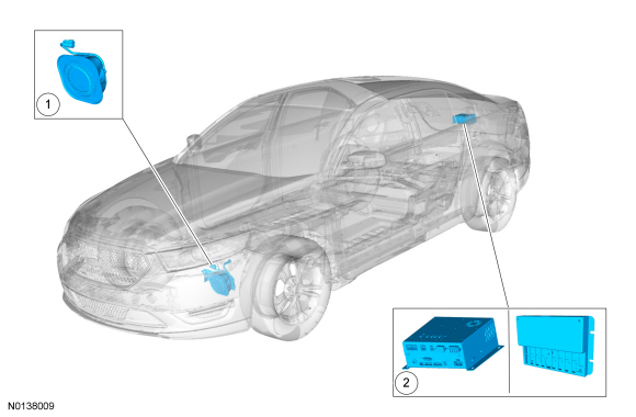
- Siren speaker
- Lighting relay center or lighting and siren control module
Overview
The siren/speaker system is used as an audible alert to the vehicle's presence.
System Operation
The lighting and siren control module generates the siren pattern and receives input from the microphone and an output to the underhood siren speaker.
Component Description
Lighting and Siren Control Module
The lighting and siren control module controls the siren/speaker system. It has a microphone input and a built-in amplifier to power the siren/speaker system.
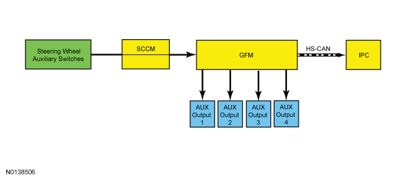
Steering Wheel Auxiliary Controls
Component Location
- GFM
- 14-Way customer access inline connector
- RH steering wheel switch
Overview
The steering wheel auxiliary controls allow the operation of 4 independent outputs of the GFM by 2 switches mounted on the steering wheel.
System Operation
System Diagram
Network Message Chart
IPC Network Input Messages
Steering Wheel Auxiliary Controls
The steering wheel auxiliary controls use 2 switches labeled AUX and 4 positions labeled 1, 2, 3 and 4. Each switch position controls an output of the GFM. Each output of the module is switched to ground when commanded on. When the switch is pressed to one of the positions, the IPC message center displays AUX1, AUX2, AUX3 or AUX4, depending on the position selected, the GFM output will turn on and the outputs remain in that state until the switch is pressed again, then the outputs turn off.
Component Description
Steering Wheel Auxiliary Switches
The steering wheel auxiliary switches are located in the RH lower switch pack of the steering wheel. Each of the 2 switches are a 2-way momentary contact switch.
Generic Function Module (GFM)
The GFM receives input from the SCCM when the steering wheel switches are activated. The GFM then provides a grounded output for any equipment connected to it.
DIAGNOSIS AND TESTING
Lighting, Siren and Speaker System
Special Tool(s)
DTC Charts
Diagnostics in this manual assume a certain skill level and knowledge of Ford-specific diagnostic practices. Refer to Diagnostic Methods in Section 100-00 for information about these practices.
GFM DTC Chart
Symptom Chart
Diagnostics in this manual assume a certain skill level and knowledge of Ford-specific diagnostic practices. Refer to Diagnostic Methods in Section 100-00 for information about these practices.
Symptom Chart: Police Package Equipment
Pinpoint Tests
Pinpoint Test A: The Spotlamp Is Inoperative Or Always On
Diagnostic OverviewDiagnostics in this manual assume a certain skill level and knowledge of Ford-specific diagnostic practices. Refer to Diagnostic Methods in Section 100-00 for information about these practices.
Refer to Wiring Diagrams Cell 96 , Police Option for schematic and connector information.
Normal Operation and Fault Conditions
The spotlamp is supplied voltage from the BCM. Ground is supplied internally by the spotlamp.
-
Possible Sources
- Fuse
- Wiring, terminals or connectors
- Spotlamp
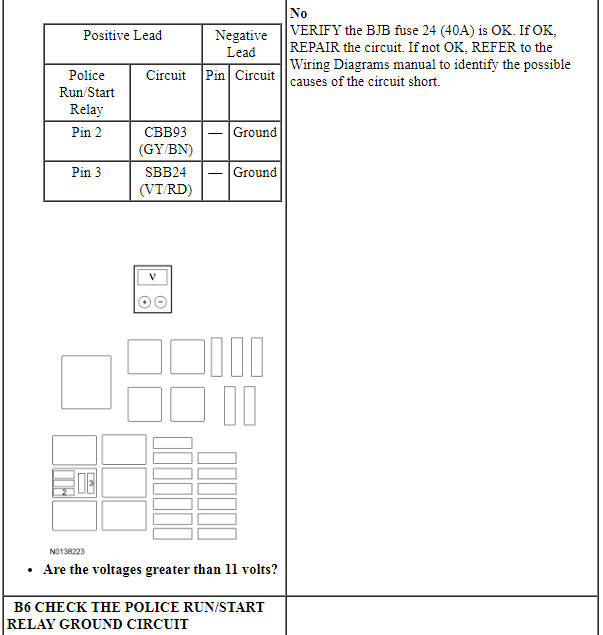
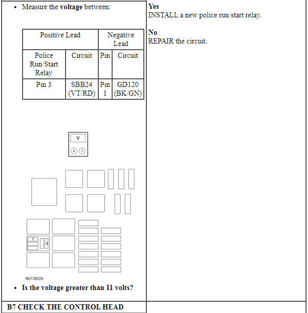
PINPOINT TEST A: THE SPOTLAMP IS INOPERATIVE OR ALWAYS ON
Pinpoint Test B: All Flashing LEDs Are Inoperative
Diagnostic Overview
Diagnostics in this manual assume a certain skill level and knowledge of Ford-specific diagnostic practices. Refer to Diagnostic Methods in Section 100-00 for information about these practices.
Refer to Wiring Diagrams Cell 96 , Police Option for schematic and connector information.
Normal Operation and Fault Conditions
REFER to Lighting, Siren and Speaker System.
-
Possible Sources
- Fuse
- Wiring, terminals or connectors
- Switch pad
- Lighting and siren control module
- Lighting relay center
-
Visual Inspection and Diagnostic Pre-checks
- Verify the lighting and siren control module (if equipped) 20A main power fuse is OK.
- Verify the lighting relay center or lighting and siren control module 10A output fuses are OK.
- Check for stuck or broken buttons on the control head.
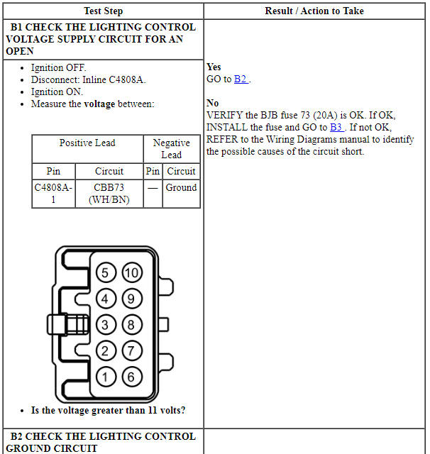
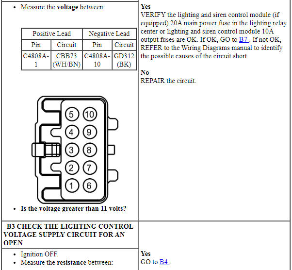
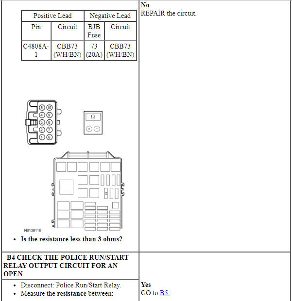
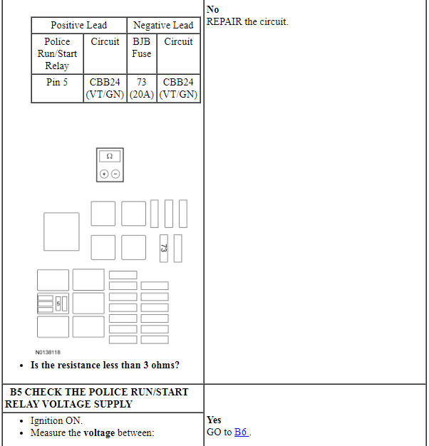
PINPOINT TEST B: ALL FLASHING LEDs ARE INOPERATIVE
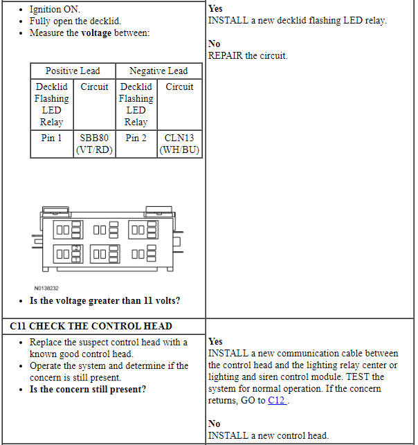
Pinpoint Test C: An Individual Or Group Of Flashing LEDs Is Inoperative Or Always On
Diagnostic Overview
Diagnostics in this manual assume a certain skill level and knowledge of Ford-specific diagnostic practices. Refer to Diagnostic Methods in Section 100-00 for information about these practices.
Refer to Wiring Diagrams Cell 96 , Police Option for schematic and connector information.
Normal Operation and Fault Conditions
REFER to Lighting, Siren and Speaker System.
-
Possible Sources
- Fuse
- Wiring, terminals or connectors
- Flashing LED
- Switch pad
- Lighting and siren control module
- Lighting relay center
-
Visual Inspection and Diagnostic Pre-checks
- Verify the lighting relay center or lighting and siren control module 10A output fuses are OK.
- Check for stuck or broken buttons on the control head.
PINPOINT TEST C: AN INDIVIDUAL OR GROUP OF FLASHING LEDs IS INOPERATIVE OR ALWAYS ON
Pinpoint Test D: An Individual Or Group Of Flashing LEDs Do Not Synchronize Correctly Or Display An Incorrect Pattern
Diagnostic Overview
Diagnostics in this manual assume a certain skill level and knowledge of Ford-specific diagnostic practices. Refer to Diagnostic Methods in Section 100-00 for information about these practices.
Refer to Wiring Diagrams Cell 96 , Police Option for schematic and connector information.
Normal Operation and Fault Conditions
The front park/turn/warn, tail lamp and front corner flashing LEDs typically have 2 versions of each pattern. If the flashing LEDs are set to the same version of the pattern, they will flash on and off at exactly the same time. If the flashing LEDs are set to different versions of the same pattern, they will flash on and off at exactly opposite times. If the flashing LEDs are out of synchronization, the on and off flash of the flashing LEDs may overlap and not flash the same or opposite.
The grille, high mount and liftgate flashing LEDs typically have 4 versions of each pattern. These flashing LEDs are made up of 6 individual LEDs. The addition of two more version of patterns control each side (3 LEDs) of an individual flashing LED. This allows the synchronization of each side of a singe flashing LED as well as each side of the vehicle.
REFER to Lighting, Siren and Speaker System.
-
Possible Sources
- Wiring, terminals or connectors
- Flashing LED
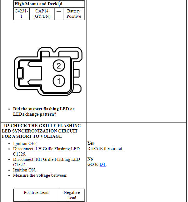
PINPOINT TEST D: AN INDIVIDUAL OR GROUP OF FLASHING LEDs DO NOT SYNCHRONIZE CORRECTLY OR DISPLAY AN INCORRECT PATTERN
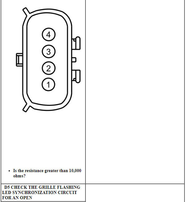

Pinpoint Test E: The Front Park/Turn/Warn LEDs Are Inoperative Or Do Not Operate Correctly
Diagnostic Overview
Diagnostics in this manual assume a certain skill level and knowledge of Ford-specific diagnostic practices. Refer to Diagnostic Methods in Section 100-00 for information about these practices.
Refer to Wiring Diagrams Cell 96 , Police Option for schematic and connector information.
Normal Operation and Fault Conditions
REFER to Lighting, Siren and Speaker System.
-
Possible Sources
- Fuse
- Wiring, terminals or connectors
- Flashing LED
- Switch pad
- Lighting and siren control module
- Lighting relay center
-
Visual Inspection and Diagnostic Pre-checks
- Verify the lighting relay center or lighting and siren control module 10A output fuses are OK.
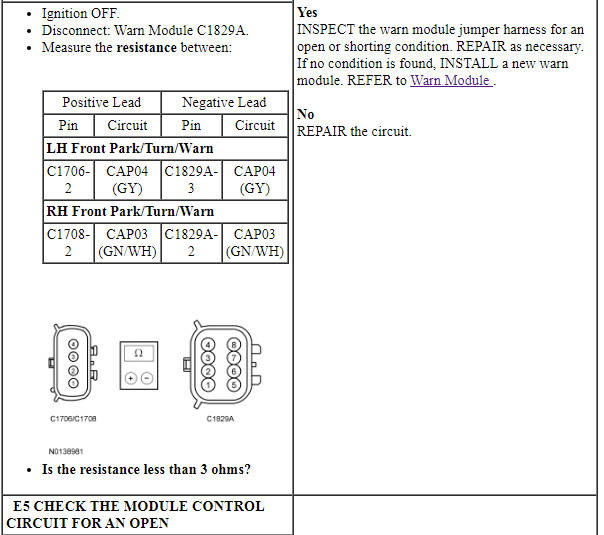
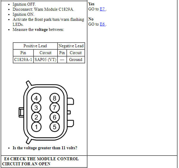
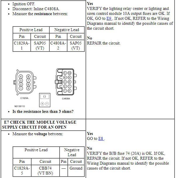
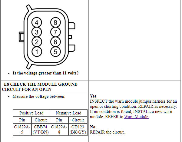
PINPOINT TEST E: THE FRONT PARK/TURN/WARN LEDS ARE INOPERATIVE OR DO NOT OPERATE CORRECTLY
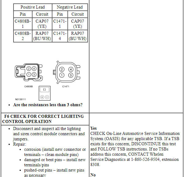
Pinpoint Test F: The Siren/Speaker Is Inoperative
Diagnostic Overview
Diagnostics in this manual assume a certain skill level and knowledge of Ford-specific diagnostic practices. Refer to Diagnostic Methods in Section 100-00 for information about these practices.
Refer to Wiring Diagrams Cell 96 , Police Option for schematic and connector information.
Normal Operation and Fault Conditions
REFER to Lighting, Siren and Speaker System.
-
Possible Sources
- Fuse
- Wiring, terminals or connectors
- Siren speaker
- Switch pad
- Lighting and siren control module
-
Visual Inspection and Diagnostic Pre-checks
- Verify the lighting and siren control module 20A siren fuse is OK.
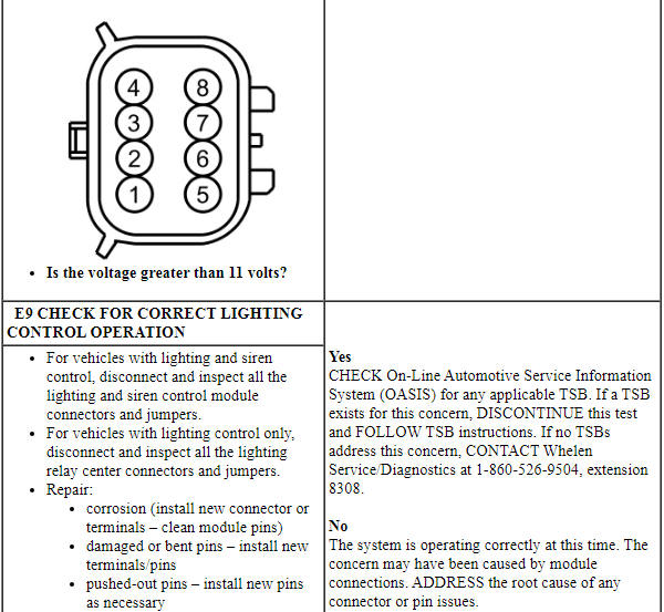
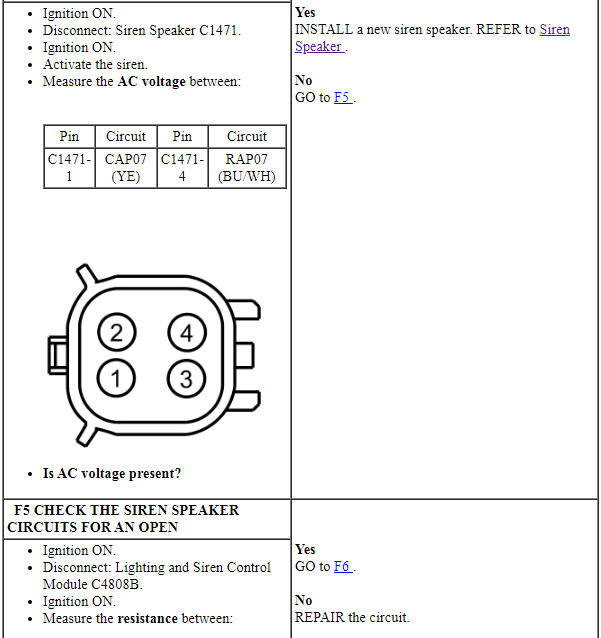
PINPOINT TEST F: THE SIREN/SPEAKER IS INOPERATIVE
Pinpoint Test G: The Steering Wheel Auxiliary Controls Are Inoperative Or Do Not Operate Correctly
Diagnostic Overview
Diagnostics in this manual assume a certain skill level and knowledge of Ford-specific diagnostic practices. Refer to Diagnostic Methods in Section 100-00 for information about these practices.
Refer to Wiring Diagrams Cell 96 , Police Option for schematic and connector information.
Normal Operation and Fault Conditions
REFER to Lighting, Siren and Speaker System.
DTC Fault Trigger Conditions
-
Possible Sources
- Wiring, terminals or connectors
- Steering wheel switch
- GFM
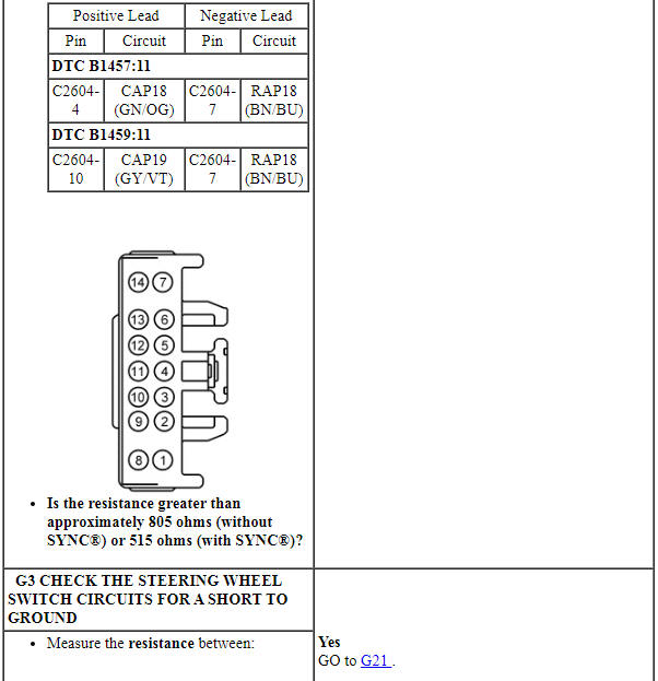
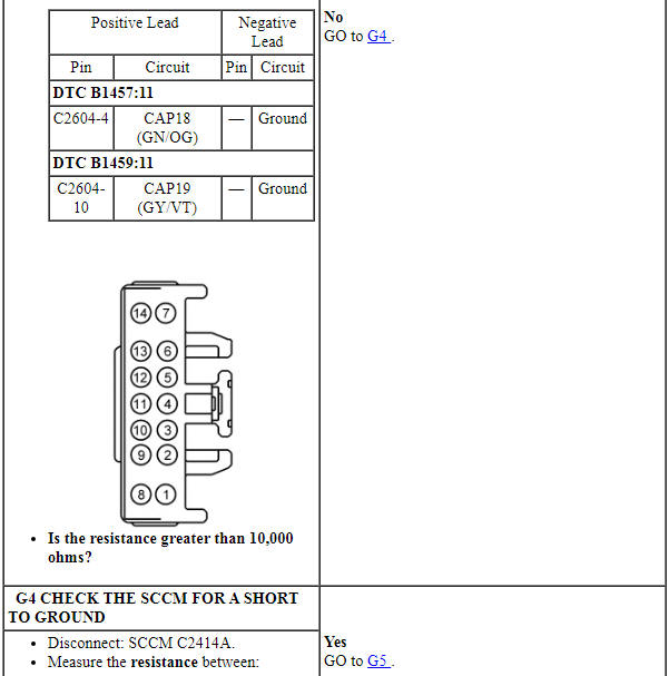
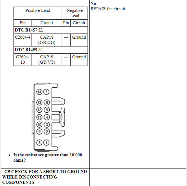
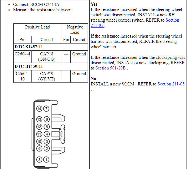
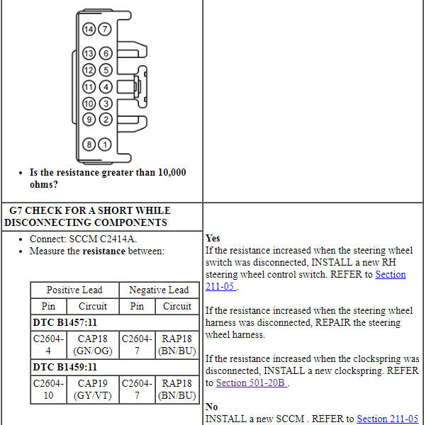
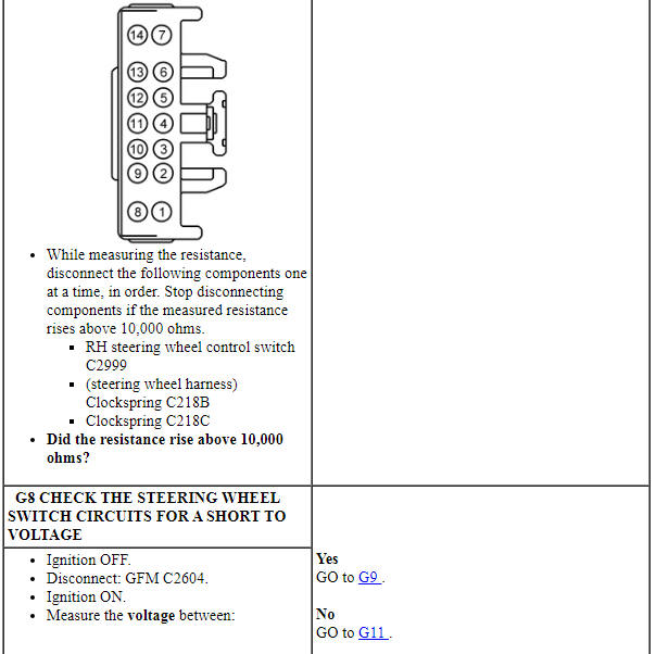
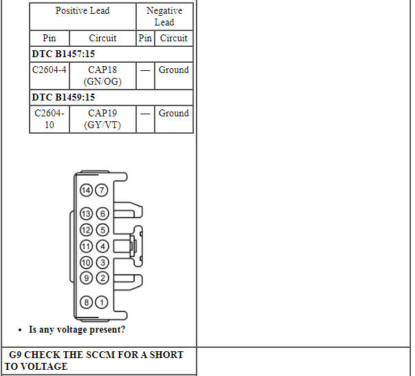
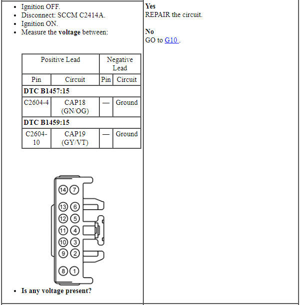
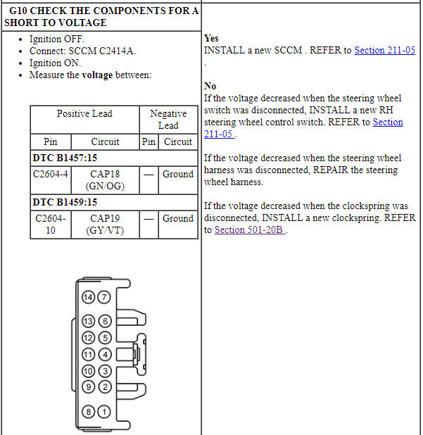
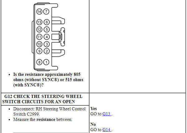
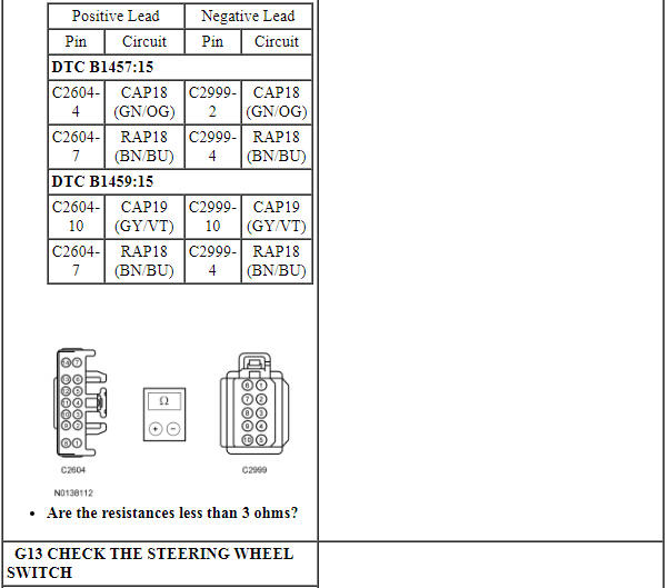
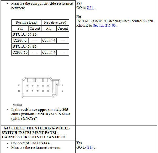
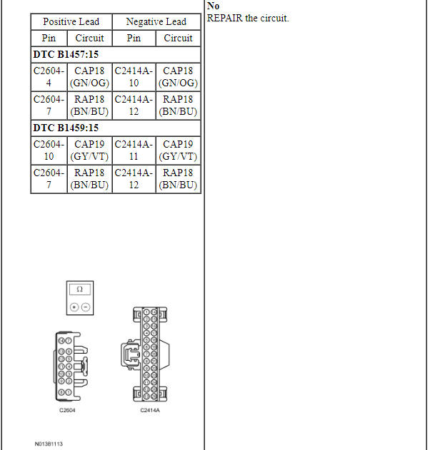
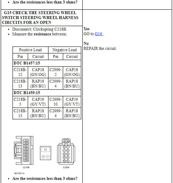
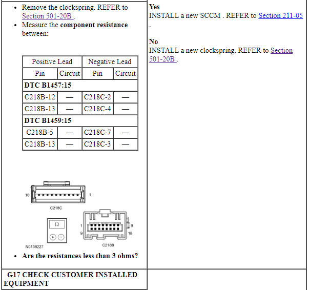
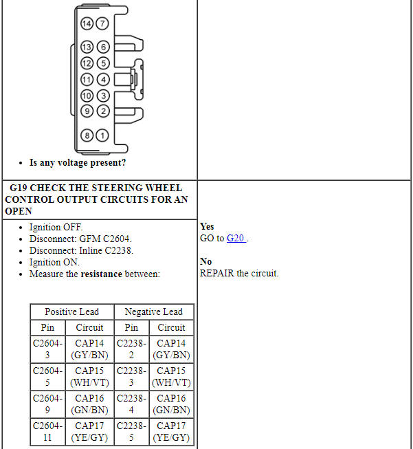
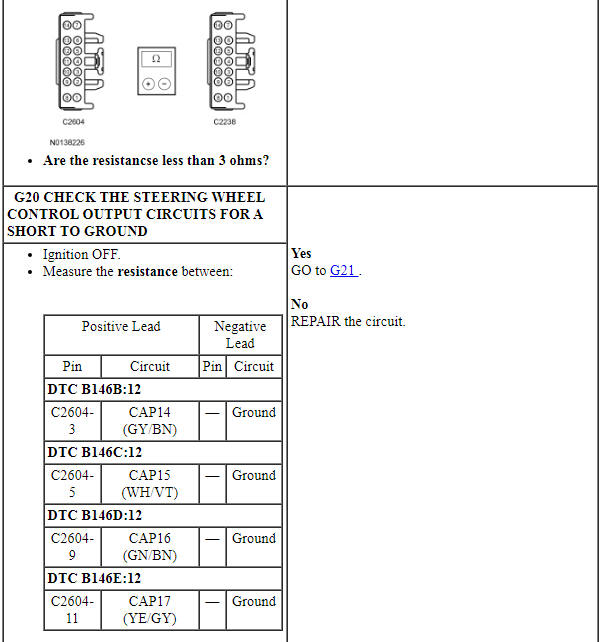
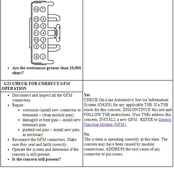
PINPOINT TEST G: THE STEERING WHEEL AUXILIARY CONTROLS ARE INOPERATIVE OR DO NOT OPERATE CORRECTLY
Pinpoint Test H: The Electronics Tray Cooling Fan Is Inoperative Or Does Not Operate Correctly
Diagnostic Overview
Diagnostics in this manual assume a certain skill level and knowledge of Ford-specific diagnostic practices. Refer to Diagnostic Methods in Section 100-00 for information about these practices.
Refer to Wiring Diagrams Cell 96 , Police Option for schematic and connector information.
Normal Operation and Fault Conditions
REFER to Lighting, Siren and Speaker System.
-
Possible Sources
- Wiring, terminals or connectors
- Fan
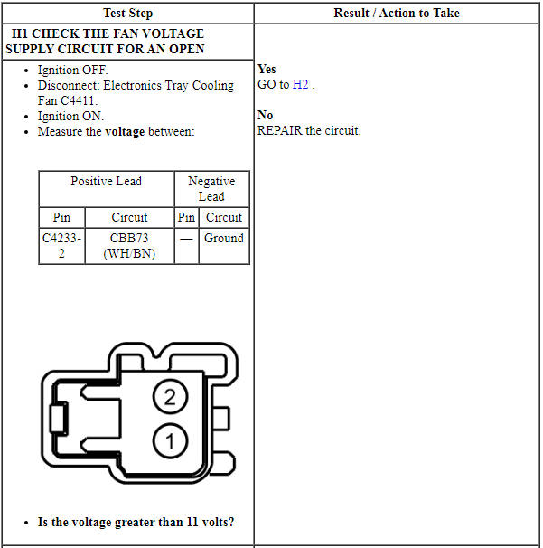
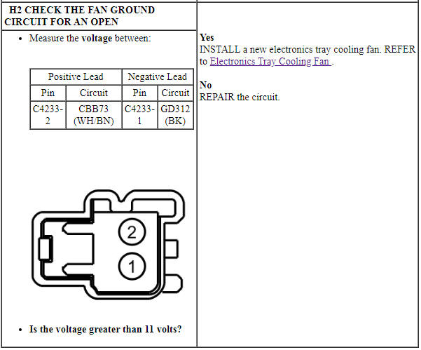
PINPOINT TEST H: THE ELECTRONICS TRAY COOLING FAN IS INOPERATIVE OR DOES NOT OPERATE CORRECTLY
GENERAL PROCEDURES
LED Flash Pattern Programming
Individual LED Flash Pattern Programming
NOTE: When cycling through flash patterns, most flash patterns include an off/on pattern followed by an inverse on/off pattern. Setting the LED on one side to the on/off and the other to off/on creates the alternating pattern effect which should not be confused with synchronization which applies to the pattern timing between LED groups. For proper synchronization, the correct flash patterns must be selected for the individual flashing LEDs. Refer to the Explorer, Taurus Police Interceptor Modifier Guide for specific flashing LED patterns.
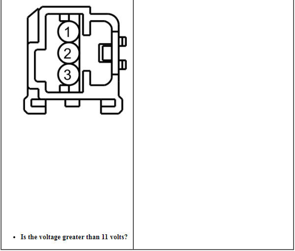
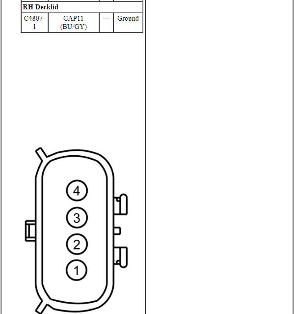
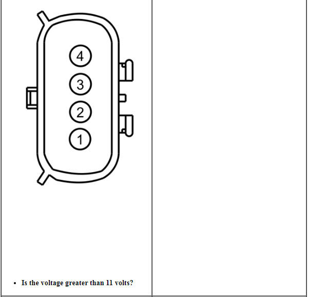
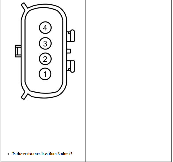
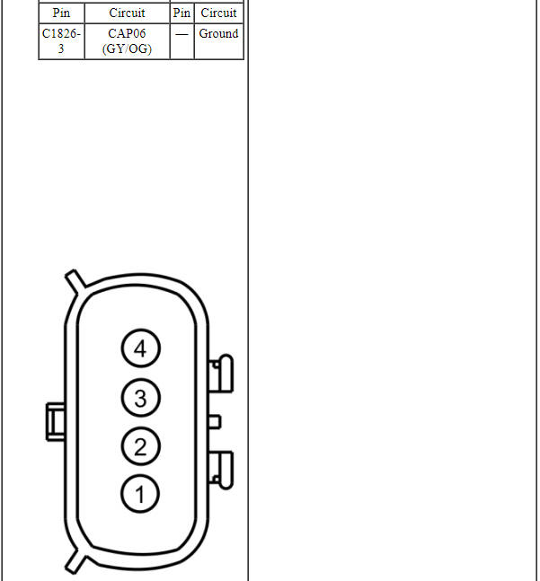
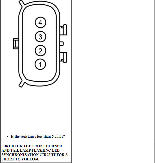
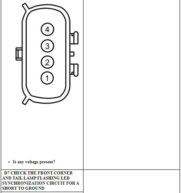
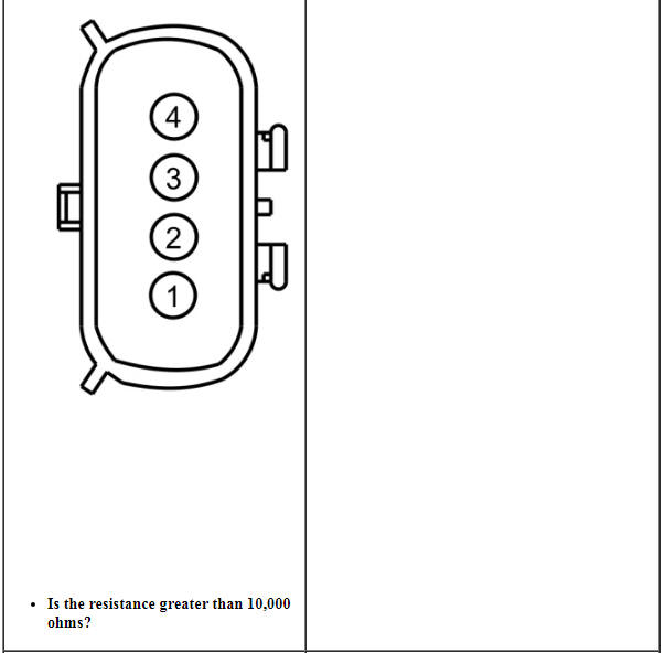
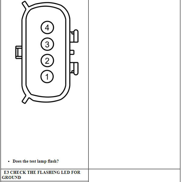
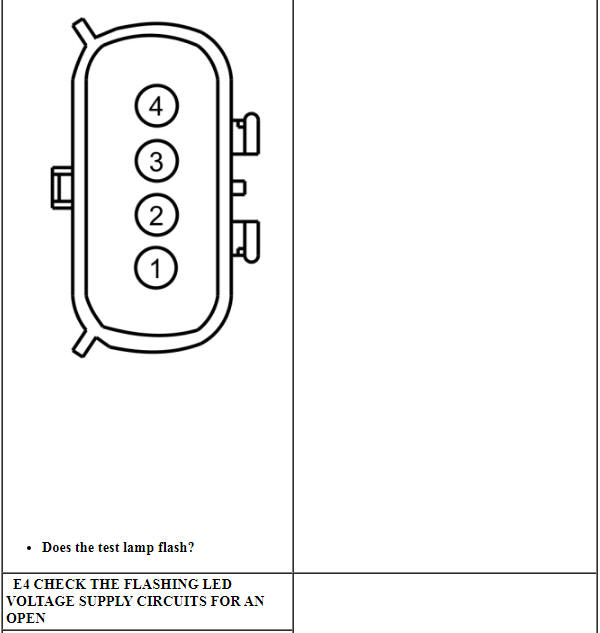
- Disconnect the flashing LED to be programmed.
- Connect ground to pin 4, component side of the flashing LED.
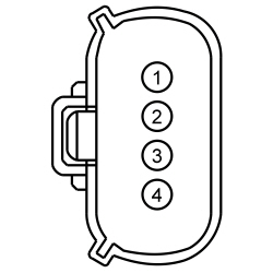
- NOTICE: This step will activate the individual flashing LED.
The flashing LED must be active to change the flash pattern.
Connect 12 volts to pin 1, component side of the flashing LED.
- Change the flashing LED flash pattern:
- To cycle forward to the next pattern, connect 12 volts to pin 2, component side of the flashing LED for less than 1 second.
- To cycle back to the previous pattern, connect 12 volts to pin 2, component side of the flashing LED for greater than 1 second.
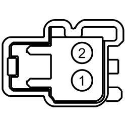
Group LED Flash Pattern Programming
NOTE: When cycling through flash patterns, most flash patterns include an off/on pattern followed by an inverse on/off pattern. Setting the LED on one side to the on/off and the other to off/on creates the alternating pattern effect which should not be confused with synchronization which applies to the pattern timing between LED groups. For proper synchronization, the correct flash patterns must be selected for the individual flashing LEDs. Refer to the Explorer, Taurus Police Interceptor Modifier Guide for specific flashing LED patterns.
- Activate the flashing LEDs in the group to be programmed.
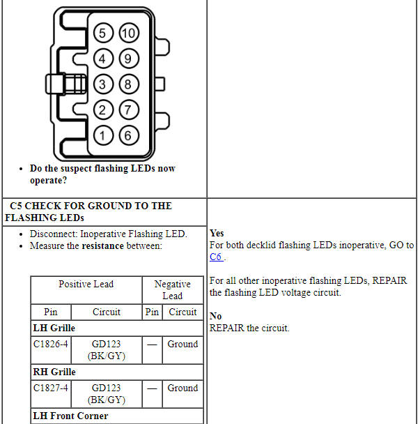
- Locate the pattern programming circuits at inline C4231. To change the
flashing pattern:
- For park/turn/warn, grille, front corner and tail lamp flashing LEDs:
- To cycle forward to the next pattern, connect 12 volts to pin 2 of inline C4231 for less than 1 second.
- To cycle back to the previous pattern, connect 12 volts to pin 2 of inline C4231 for greater than 1 second.
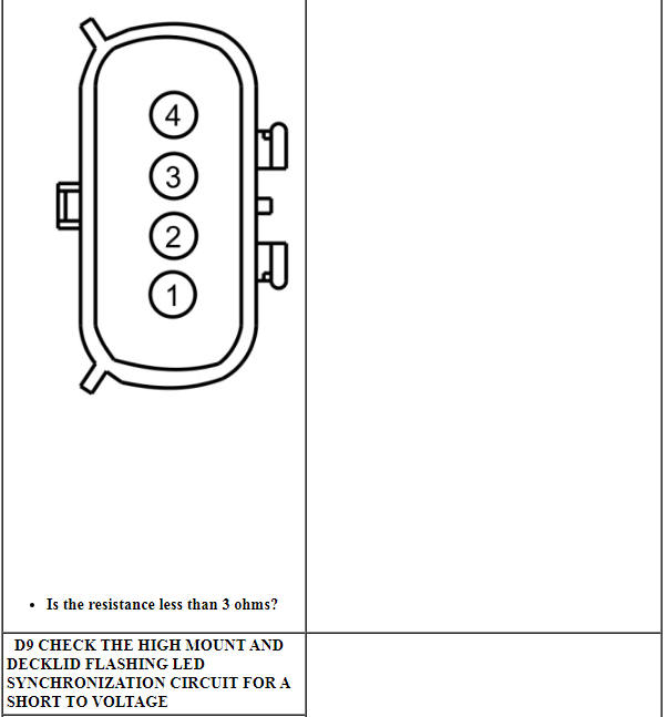
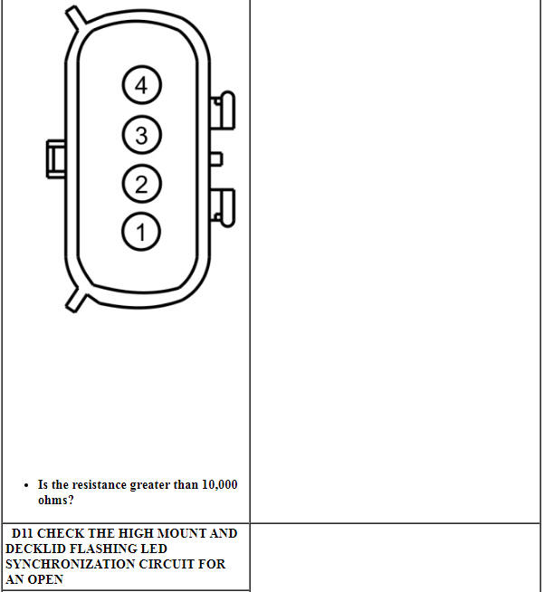
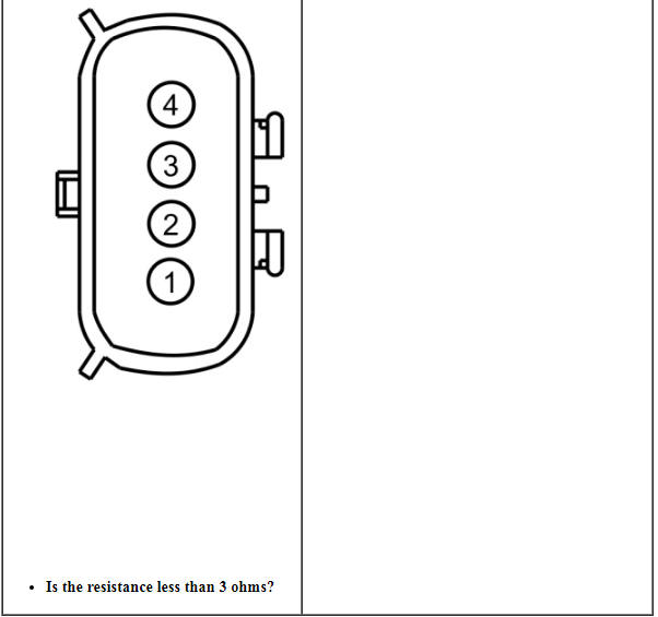
- For high mount and decklid flashing LEDs:
- To cycle forward to the next pattern, connect 12 volts to pin 1 of inline C4231 for less than 1 second.
- To cycle back to the previous pattern, connect 12 volts to pin 1of inline C4231 for greater than 1 second.
- For park/turn/warn, grille, front corner and tail lamp flashing LEDs:
REMOVAL AND INSTALLATION
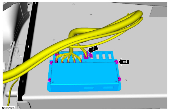
Lighting and Siren Control Module
Removal
NOTE: CenCom Gold shown, others similar.
-
- To install, tighten the nuts and bolts to 6 Nm (53 lb-in).
Installation
- To install, reverse the removal procedure.
Lighting Relay Center
Removal
-
- To install, tighten the nuts and bolts to 6 Nm (53 lb-in).
Installation
- To install, reverse the removal procedure.
Warn Module
Removal
- Remove the RH headlamp assembly. For additional information, refer to section Section 417-01.
Installation
- To install, reverse the removal procedure.
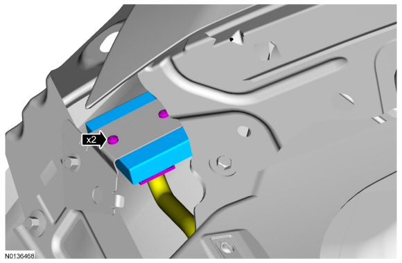
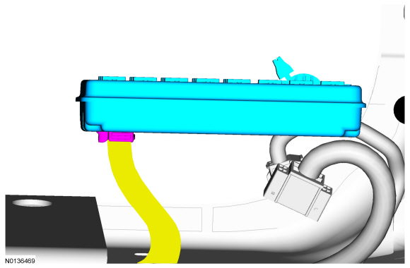
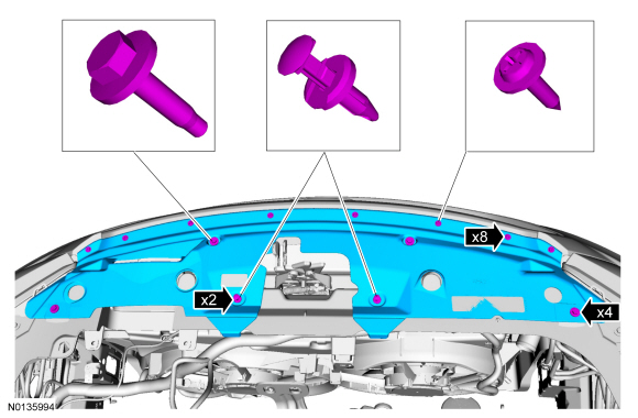
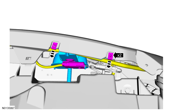
Switch Pad
Removal
NOTE: The switch pad for the lighting and siren control module is shown, the switch pad for the lighting relay center is similar.
NOTE: Mounting location is determined by the customer and will vary.
- Separate the switch pack from the mounting location.
- Remove and discard the 2-sided tape.
Installation
- To install, reverse the removal procedure.
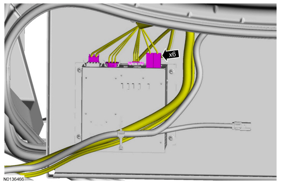
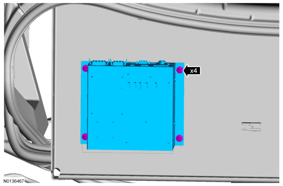
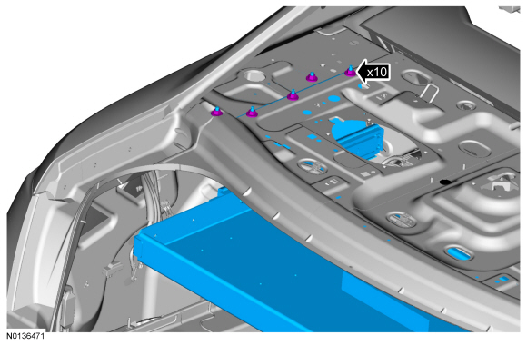
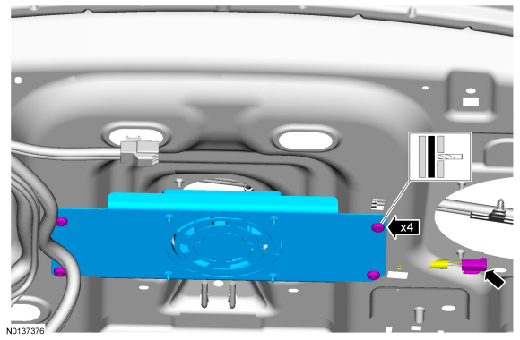
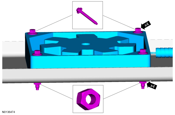
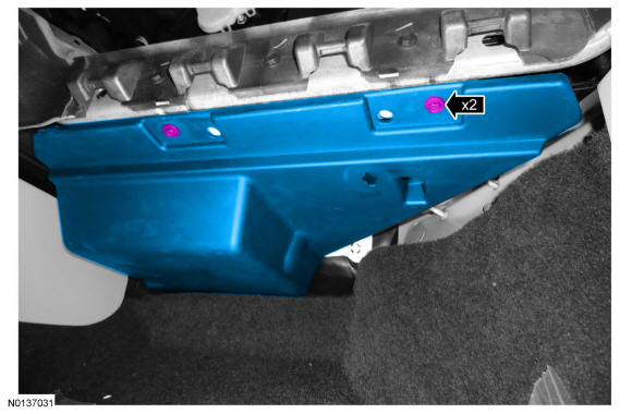
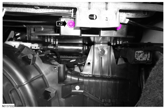
Electronics Tray
Removal
- Remove the lighting and siren control module (Whelan CenCom) or lighting relay center (Whelan PCC8R). For additional information, refer to Lighting and Siren Control Module or Lighting Relay Center.
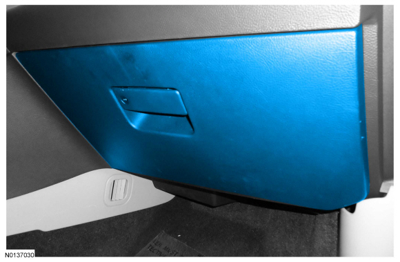
- Remove the parcel shelf trim panel. For additional information, refer to Section 501-05.
- Five on each side.
- To install, tighten the bolts and nuts to 25 Nm (18 lb-ft).
Installation
- To install, reverse the removal procedure.
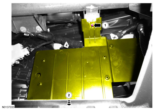
Electronics Tray Cooling Fan
Removal
- Remove the police electronics tray. For additional information, refer to Electronics Tray.
-
- To install, install new rivets.
Installation
- To install, reverse the removal procedure.
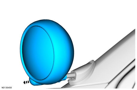
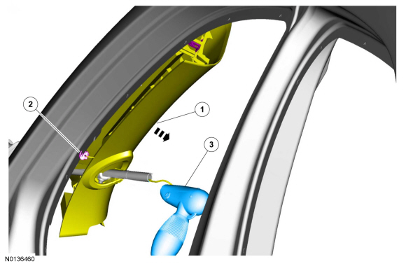
Grille Flashing LED
Removal
Installation
- To install, reverse the removal procedure.
Front Corner Flashing LED
Removal
- Remove the headlamp assembly. For additional information, refer to Section 417-01.
Installation
- To install, reverse the removal procedure.
Front Park/Turn/Warn LED Assembly
Removal
Installation
- To install, reverse the removal procedure.
High Mount Flashing LED
Removal
- Remove the headliner. For additional information, refer to Section 501-05.
Installation
- To install, reverse the removal procedure.
Removal
- Remove the rear lamp assembly. For additional information, refer to Section 417-01.
Installation
- To install, reverse the removal procedure.
Decklid Flashing LED
Removal
Installation
- To install, reverse the removal procedure.
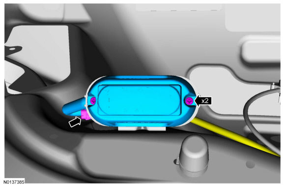
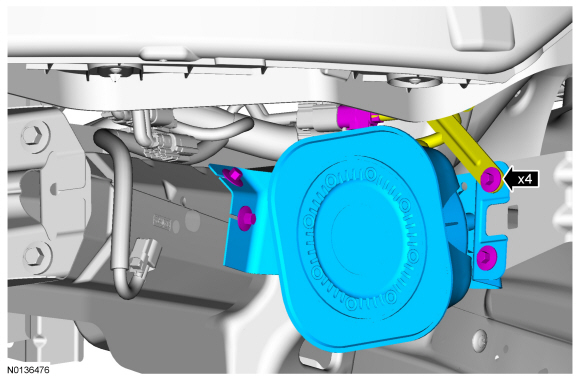
Siren Speaker
Removal
- Remove the front bumper cover. For additional information, refer to Section 501-19.
-
- To install, tighten bolts to 13 Nm (10 lb-ft).
Installation
- To install, reverse the removal procedure.
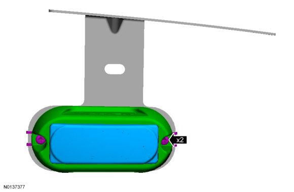
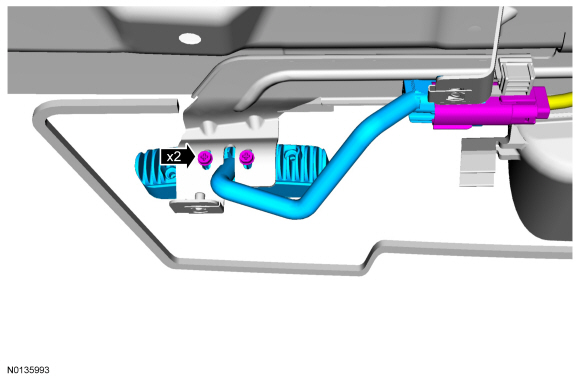
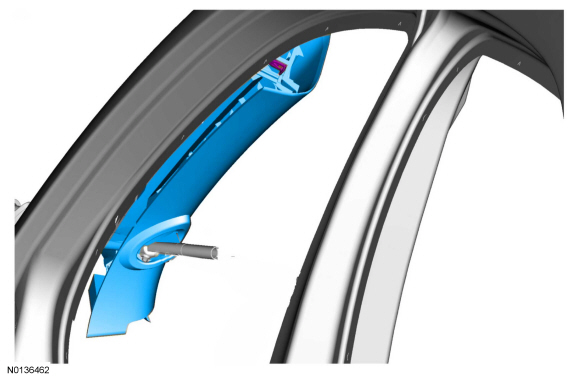
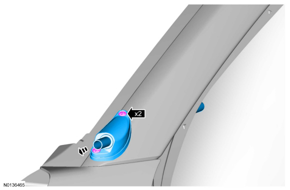
Spotlamp
Removal
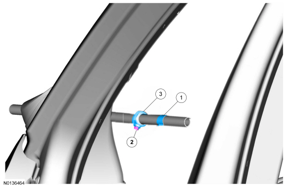
- NOTE: Push the loosened screw to release the wedge nut.
To install, tighten to 7 Nm (62 lb-in).
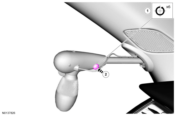

- To install, make sure the wedge nut aligns with the keyway on the spotlamp shaft.
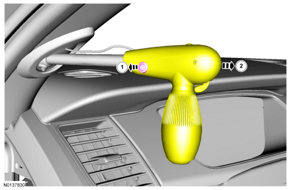
- To install, tighten the set screw so that there is a slight drag on the spotlamp shaft.
Installation
- To install, reverse the removal procedure.
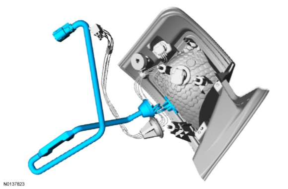
Generic Function Module (GFM)
Removal
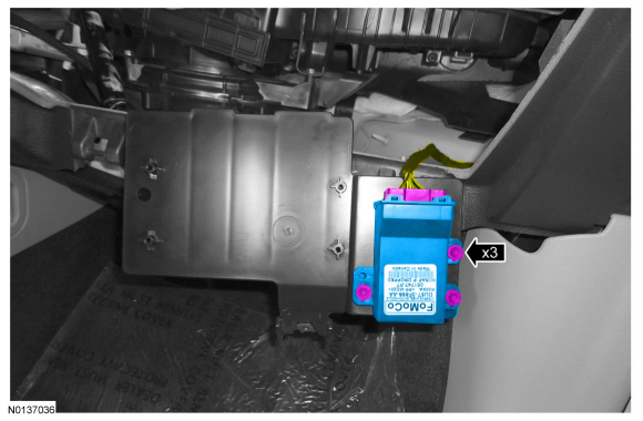
Installation
- To install, reverse the removal procedure.
 Noise, Vibration and Harshness (NVH) - Diagnosis and Testing
Special Tool(s)
Diagnostic Theory
The shortest route to an accurate diagnosis results from:
system knowledge, including comparison with a known good system.
system history, including repair histo ...
 Chassis
...
Other materials:
General Procedures
Audio Control Module (ACM) Self-Diagnostic Mode
NOTE: If the Audio Front Control Module (ACM) is completely
inoperative (does not power up), the part number decal on the Audio Front
Control Module (ACM) chassis can be used to attain the ACM part number.
Turn the ACM on.
...
General Procedures
Audio Control Module (ACM) Self-Diagnostic Mode
NOTE: If the ACM is completely inoperative (does not power up), the
part number decal on the ACM chassis can be used to attain the ACM part number.
Turn the ACM on.
Operate the audio system in radio tu ...
Specifications, Description and Operation
SPECIFICATIONS
Torque Specifications
DESCRIPTION AND OPERATION
Information and Entertainment System
Component Location
Overview
The audio system consist of a 4 (police package) or 6 speaker system, with an
AM/FM single CD ACM,
4.2 inch non-touchscreen FCDIM, FCIM,
audio inp ...
