
WARNING:
Always use floor mats that are designed to fit the foot well of your vehicle, leaving the pedal area unobstructed, and which can be firmly secured to retention posts so that they cannot slip out of position and interfere with the pedals or impair safe operation of your vehicle in other ways.
• Incorrectly fitted floor mats can cause the accelerator pedal to become stuck in the open position. This can cause loss of vehicle control.
• Always correctly install the floor mats to the retention posts so that they cannot slip out of position or obstruct pedal operation.
• Do not place unsecured floor mats or any other covering in the foot well.
• Do not place additional floor mats or any other covering on top of the original floor mats. This will reduce the pedal clearance and interfere with the pedal operation.
• Do not allow objects to fall or become trapped under the pedals of your vehicle. This can cause loss of vehicle control.
• Carry out regular inspections to make sure the floor mats are secure.
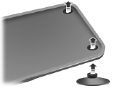
To install the floor mats, position the floor mat eyelet over the retention post and press down to lock in position.
Remove in reverse order.
 Driving through water
WARNING: Drive through water in an emergency only, and not
as part of normal driving.
WARNING: Engine damage can occur if water enters the air
filter.
Note: Driving through deep water may allow wa ...
 Roadside Emergencies
Vehicles Sold in the United States: Getting Roadside Assistance
To fully assist you should you have a vehicle concern, Ford Motor
Company offers a complimentary Roadside Assistance program.
This ...
Other materials:
Using sync with your media player
You can access and play music from your digital music player over the
vehicle’s speaker system using the system’s media menu or voice
commands. You can also sort and play your music by specific categories,
such as artists, albums, etc.
SYNC is capable of hosting nearly any digital media pl ...
Universal Garage Door Opener (If Equipped)
HomeLink® wireless control system
WARNING: Make sure that the garage door and security device
are free from obstruction when you are programming. Do not
program the system with the vehicle in the garage.
WARNING: Do not use the system with any garage door opener
that does not have the safety s ...
General Procedures
Valve Clearance Check
Remove the RH fender splash shield. For additional information, refer
to Section 501-02.
Remove the valve cover. For additional information, refer to Valve
Cover in this section.
NOTE: Turn the engine clockwise only, and only use the crankshaft
...
