SPECIFICATIONS
Torque Specifications
DESCRIPTION AND OPERATION
Brake Booster
The power brake actuation system includes a vacuum sorce (engine manifold or vacuum pump), vacuum assisted brake booster, vacuum check valve and a vacuum supply tube. Vehicles equipped with 3.5L and 3.7L engines utilize engine manifold vacuum and vehicles equipped with 2.0L GTDI engines utilize an engine-mounted/cam-driven vacuum pump and engine manifold vacuum to supply vacuum.
Vacuum is delivered through the vacuum supply tube to the vacuum check valve. The vacuum check valve is a one-way valve that allows supplied vacuum to the booster then closes when the vacuum supply is removed. The vacuum is applied to a rubber diaphragm on the vacuum side of the brake booster chamber which then pulls the piston rod in when the brakes are applied to provide power assist, reducing the amount of effort required at the brake pedal to actuate the foundation brakes.
REMOVAL AND INSTALLATION
Brake Booster
Removal
WARNING: Before beginning any service procedure in this section, refer to Safety Warnings in Section 100-00. Failure to follow this instruction may result in serious personal injury.
NOTE: Removal steps in this procedure may contain installation details.
All vehicles
-
- To install, tighten to 63 Nm (46 lb-ft).
Vehicles equipped with 3.5 L Ti-VCT, 3.7L Ti-VCT or 2.0L Gasoline Turbocharged Direct Injection (GTDI) engines
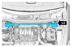
- Remove the Air Cleaner (ACL) outlet pipe. Refer to Section 303-12.
- Remove the Hydraulic Control Unit (HCU). Refer to Section 206-09.
Vehicles equipped with 3.5L GTDI engine
-
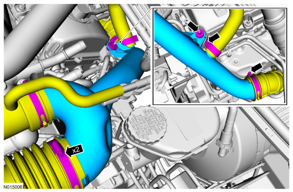
- To install, tighten the nut to 6 Nm (53 lb-in).
- To install, tighten the clamps to 5 Nm (44 lb-in)
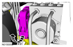
- Disconnect the ABS module electrical connector.
All vehicles
- Remove the brake master cylinder. Refer to Section 206-06.
- NOTICE: Do not service the brake pedal or brake booster
without first removing the stoplamp switch. This switch must be removed with
the brake pedal in the at-rest position. The switch plunger must be
compressed for the switch to rotate in the bracket. Attempting to remove the
switch when the plunger is extended (during pedal apply) will result in
damage to the switch.
Remove the stoplamp switch. Refer to Section 417-01.
- NOTE: The booster push rod clevis-locking pin is a one-time use only part. Any time the booster push rod clevis-locking pin is removed, a new booster push rod clevis-locking pin should be used. Remove the clevis-locking pin by squeezing the locking tabs and pulling outward on the opposite end.
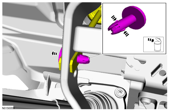
-
- To install, tighten the new nuts to 25 Nm (18 lb-ft).
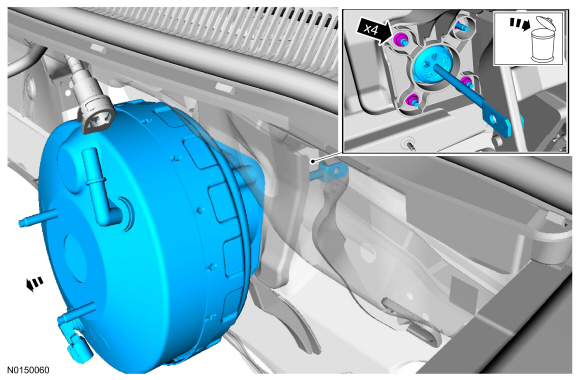
Installation
- To install, reverse the removal procedure.
Brake Vacuum Pump
Removal and Installation
NOTE: Removal steps in this procedure may contain installation details.
- Remove the air cleaner outlet pipe. For additional information, refer to Intake Air System Components-Exploded View in Section 303-12.
- To install, tighten to 10 Nm (89 lb-in).
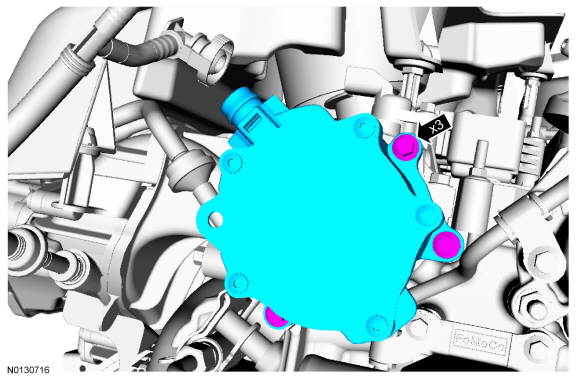
- Inspect and, if necessary, install a new brake vacuum pump gasket.
- To install, reverse the removal procedure.
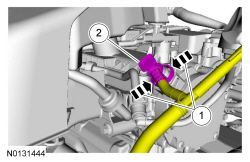
Brake Booster Vacuum Sensor

Removal
WARNING: Before beginning any service procedure in this section, refer to Safety Warnings in Section 100-00. Failure to follow this instruction may result in serious personal injury.
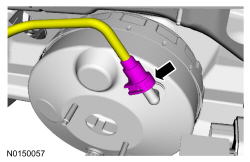
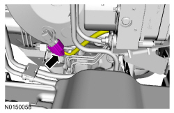
- Disconnect the brake booster vacuum sensor electrical connector.
- Remove the brake booster vacuum sensor.
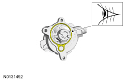
Installation
- NOTE: Please note the correct installation position in the
exploded view. It is critical that the sensor be installed in the exact
position that it was removed.
To install, reverse the removal procedure.
 Hydraulic Brake Actuation
SPECIFICATIONS
Material
Torque Specifications
DESCRIPTION AND OPERATION
Adjustable Pedals
Overview
The adjustable pedal feature uses an electrical motor to adjust the brake and
accelerator pedal po ...
 Anti-Lock Brake System (ABS) and Stability Control
SPECIFICATIONS
Torque Specifications
DESCRIPTION AND OPERATION
Anti-Lock Brake System (ABS) and Stability Control
Overview
The ABS and stability control system is comprised of the following subsystem ...
Other materials:
Instrument Panel and Console
SPECIFICATIONS
Torque Specifications
REMOVAL AND INSTALLATION
Instrument Panel - Exploded View
Instrument Panel Trim Panel and Fasteners
Instrument Panel Finish and Trim Panels
Instrument Panel Upper Section
Glove Compartment
For additional information, refer to the procedures in this sec ...
Fuel Charging and Controls - 2.0L GTDI
SPECIFICATIONS
Material
Torque Specifications
a Refer to the procedure in this section.
DESCRIPTION AND OPERATION
Fuel Charging and Controls
Component Locations
WARNING: Do
not smoke, carry lighted tobacco or have an open flame of any type when working
on or near any fuel-related component. ...
Specifications, Description and Operation
SPECIFICATIONS
Torque Specifications
DESCRIPTION AND OPERATION
Information and Entertainment System
Component Location
Overview
The audio system consist of a 7 speaker system, with an AM/FM single CD ACM,
8-inch (203 mm) touchscreen FDIM, FCIM, steering wheel controls, SYNC with
...
