SPECIFICATIONS
Material
Torque Specifications
DESCRIPTION AND OPERATION
Adjustable Pedals
Overview
The adjustable pedal feature uses an electrical motor to adjust the brake and accelerator pedal positions forward and rearward to increase driver comfort. Two adjustable pedal systems are available; one that is connected to the memory feature option and one that is not connected to the memory feature option.
System Operation
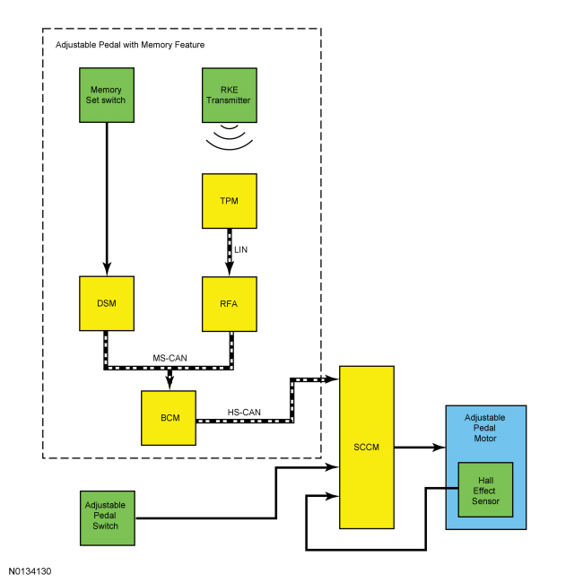
System Diagram
Network Message Chart
Module Network Input Messages: Adjustable Pedals
Adjustable Pedal System
The adjustable pedal motor directly controls the accelerator pedal through the use of a pinion and worm gear set. The other end of the motor is attached to a cable inside a sleeve, which is connected to another worm gear set on the brake pedal for the adjustment of the brake pedal. When the motor rotates, the worm gear set on the accelerator pedal and the worm gear set on the brake pedal both rotate simultaneously. The motor direction of rotation determines the direction of pedal movement, forward or rearward.
Adjustable Pedals without Memory Feature
The adjustable pedals without memory feature are controlled by the SCCM and the adjustable pedals control switch.
Adjustable Pedals with Memory Feature
The adjustable pedals with memory feature are controlled by the SCCM, BCM and DSM. The pedals can be adjusted in 3 different ways:
- Using the adjustable pedals control switch.
- Using the memory set switch, when associated with the seat/mirror/pedal position programmed into the memory that is recalled using the memory set switch.
- Using the RKE feature, when associated with a memory setting, will recall the seat/mirror/pedal positions associated with that setting
The SCCM monitors the adjustable pedal motor and circuits for concerns. If a concern is detected, the SCCM is capable of setting DTCs.
Operating with Adjustable Pedals Control Switch
The pedals can be adjusted using the adjustable pedals control switch with the ignition in OFF, ON, ACC or RUN, regardless of the gear selector position. When the adjustable pedals control switch is pressed, a signal is sent to the SCCM which then sends voltage to the adjustable pedal motor. The motor then drives the pedals either forward or rearward (depending on which direction the switch was pressed) until the switch is released.
Operating with Memory Set Switch
The pedals can be adjusted using the memory SET switch with the ignition in OFF, ON, ACC or RUN; but the gear selector must be in the PARK position. When one of the memory set positions is recalled by pressing the memory set switch, the DSM senses continuity to ground through the memory set switch circuit and sends a message to the BCM over the MS-CAN. The BCM acts as a gateway module and transmits the message to the SCCM over the HS-CAN. The SCCM then provides voltage to the adjustable pedal motor to move the pedals.
The SCCM monitors the Hall-effect sensor in the adjustable pedal motor and stops sending voltage to the motor when the required pedal position is reached. If the SCCM receives a pedal position input from the adjustable pedals control switch during a memory position recall, the module stops the memory recall and responds to the new pedal position input.
For information on setting and recalling a memory pedal position, refer to Memory Position Programming in Section 501-10.
Operating with Remote Keyless Entry (RKE)
The pedals can be adjusted using the RKE transmitter with the ignition in OFF, ON, ACC or RUN; but the gear selector must be in the PARK position. When the RKE button is pressed on the IA key, the transmitted signal is received by the TPM module. The TPM module sends a message to the RFA along a hard wired LIN. The RFA then sends the message to the BCM over the MS-CAN. The BCM acts as a gateway module and transmits the message over the HS-CAN to the SCCM. The SCCM then provides voltage to the adjustable pedal motor to move the pedals to the position programmed into the IA key.
The SCCM monitors the Hall-effect sensor in the adjustable pedal motor and stops sending voltage to the motor when the required pedal position is reached. If the SCCM receives a pedal position input from the adjustable pedals control switch during a memory position recall, the module stops the memory recall and responds to the new pedal position input.
Component Description
Adjustable Brake Pedal and Bracket
The adjustable brake pedal and bracket contains a worm gear set that allows for forward and rearward movement of the pedal. The gear is driven by a cable attached to the adjustable pedal motor.
Adjustable Pedal Motor and Cable
The adjustable pedal motor is a single-speed, reversible electric motor that contains a Hall-effect sensor for the memory feature. The motor serviced with the brake pedal assembly. The ends of the cable are keyed and the cable itself is contained in a protective, plastic sleeve. The cable is not available separately for service.
Memory Set Switch
The memory set switch is a set of 2 momentary-contact, push-button switches that allow for automatic positioning of the driver seat, power mirrors and adjustable pedals to 3 programmable positions.
Adjustable Pedals Control Switch
The adjustable pedals control switch is a 2 position, momentary-contact, rocker style switch.
Steering Column Control Module (SCCM)
For additional information, refer to Section 211-05.
DIAGNOSIS AND TESTING
DTC and Symptom Charts
DTC Chart
Diagnostics in this manual assume a certain skill level and knowledge of Ford-specific diagnostic practices. Refer to Diagnostic Methods in Section 100-00 for information about these practices.
Steering Column Control Module (SCCM) DTC Chart
Symptom Chart - Adjustable Pedals Without Memory Feature
Diagnostics in this manual assume a certain skill level and knowledge of Ford-specific diagnostic practices. Refer to Diagnostic Methods in Section 100-00 for information about these practices.
Symptom Chart - Adjustable Pedals Without Memory Feature
Symptom Chart - Adjustable Pedals With Memory Feature
Diagnostics in this manual assume a certain skill level and knowledge of Ford-specific diagnostic practices. Refer to Diagnostic Methods in Section 100-00 for information about these practices.
Symptom Chart - Adjustable Pedals With Memory Feature
Diagnostic Routines
Special Tool(s)
Diagnostic Routines
Pinpoint Test A: The Adjustable Pedals Only Move in 1-Second Intervals
Diagnostic Overview
Diagnostics in this manual assume a certain skill level and knowledge of Ford-specific diagnostic practices. Refer to Diagnostic Methods in Section 100-00 for information about these practices.
Refer to Wiring Diagrams Cell 127, Adjustable Pedals for schematic and connector information.
Normal Operation and Fault Conditions
The SCCM uses a Hall-effect sensor integral to the motor to identify the current pedal position. The SCCM sends a reference voltage along the sensor feed circuit, through the Hall-effect sensor and back to the SCCM along the signal return circuit.
When one or more of the following DTCs set, the adjustable pedals enter a "jog mode". The memory system recall will not function from either the memory set switch or the RKE transmitter while the pedals are in jog mode. The motor moves the pedals for only one second regardless of the length of time the adjustable pedals control switch is actually pressed.
DTC Fault Trigger Conditions
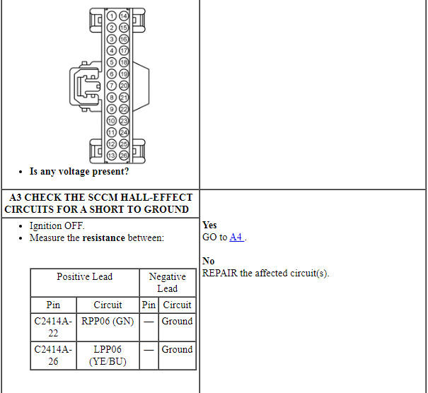
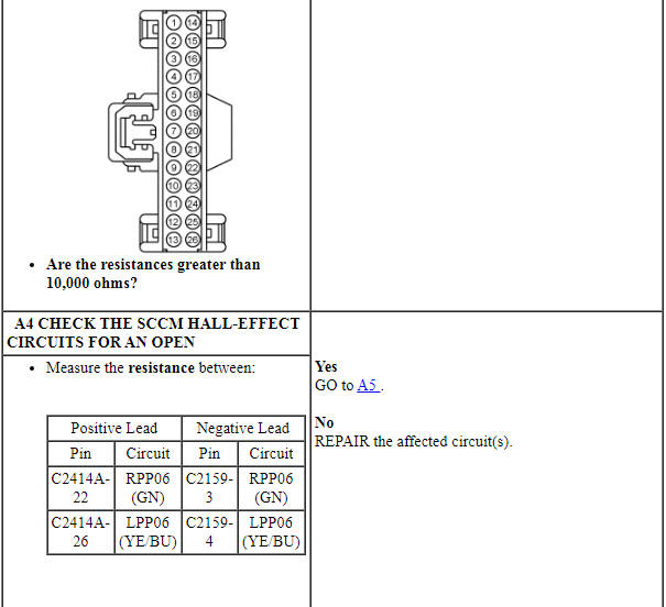
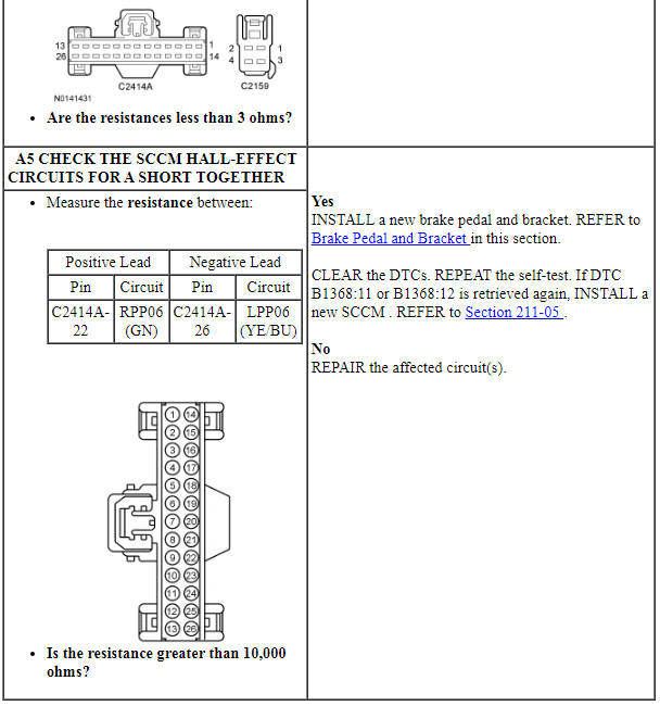
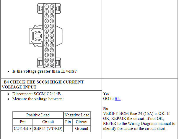
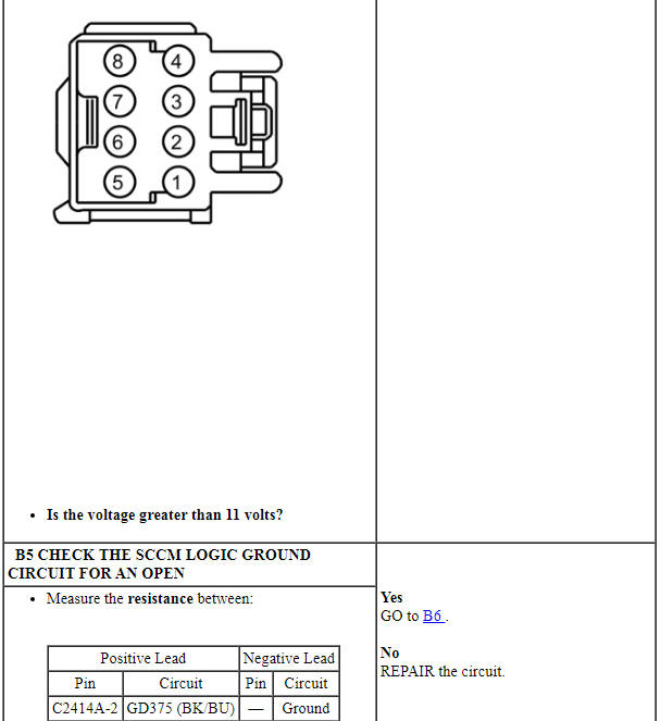
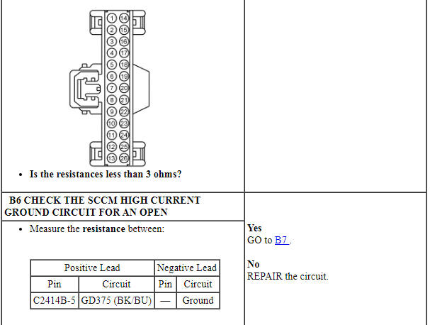
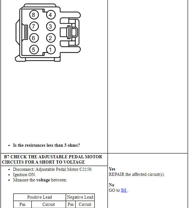
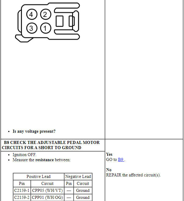
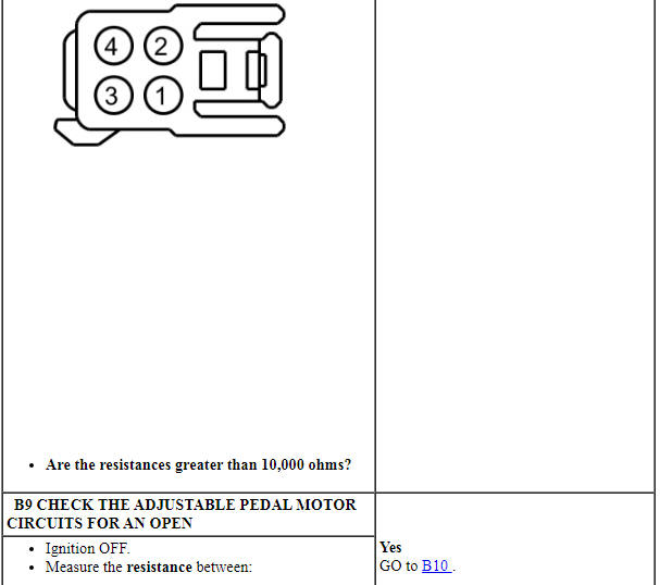
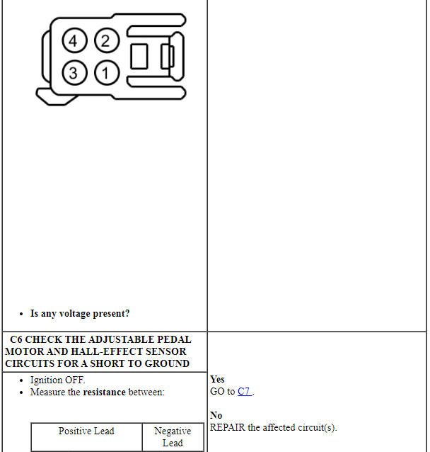
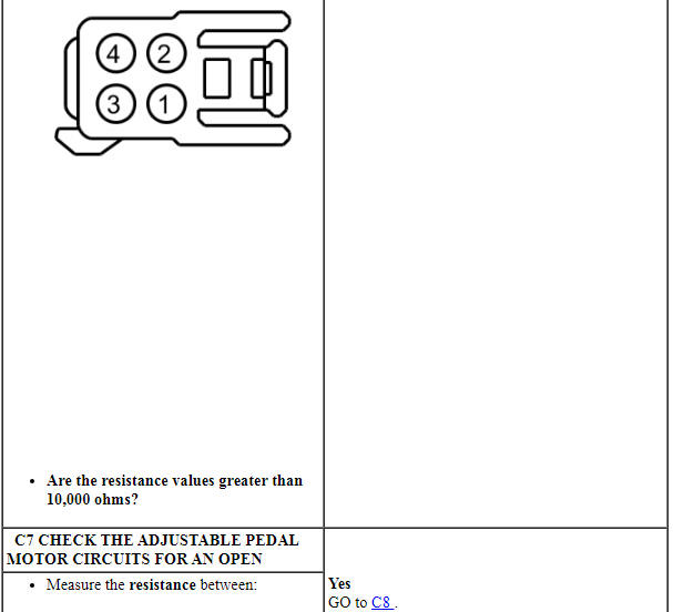
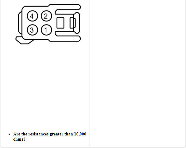
PINPOINT TEST A: THE ADJUSTABLE PEDALS ONLY MOVE IN 1-SECOND INTERVALS
Pinpoint Test B: The Adjustable Pedals are Inoperative or Do Not Operate Correctly - Using the Adjustable Pedals Control Switch
Diagnostic Overview
Diagnostics in this manual assume a certain skill level and knowledge of Ford-specific diagnostic practices. Refer to Diagnostic Methods in Section 100-00 for information about these practices.
Refer to Wiring Diagrams Cell 127, Adjustable Pedals for schematic and connector information.
Normal Operation and Fault Conditions
The SCCM receives fused battery voltage from the BCM.
Pressing the adjustable pedals control switch causes the SCCM to send current along one circuit to the adjustable pedal motor. The current returns to the SCCM along another circuit and is grounded through the SCCM, this moves the pedals in the desired direction. Pressing the adjustable pedals control switch in the opposite direction reverses the current flow through the circuits and moves the pedals in the opposite direction.
DTC Fault Trigger Conditions
Visual Inspection and Diagnostic Pre-checks
Inspect BCM fuses 23 (15A) and 24 (15A).
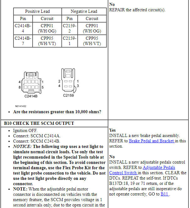
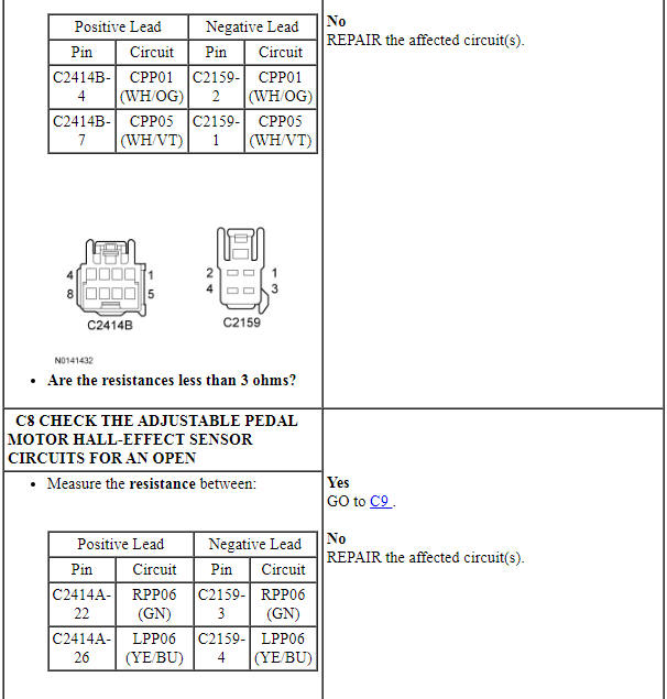
PINPOINT TEST B: THE ADJUSTABLE PEDALS ARE INOPERATIVE OR DO NOT OPERATE CORRECTLY - USING THE ADJUSTABLE PEDALS CONTROL SWITCH

Pinpoint Test C: The Adjustable Pedals are Inoperative or Do Not Operate Correctly - Using the Memory SET Switch Buttons or the RKE Transmitter
Diagnostic Overview
Diagnostics in this manual assume a certain skill level and knowledge of Ford-specific diagnostic practices. Refer to Diagnostic Methods in Section 100-00 for information about these practices.
Refer to Wiring Diagrams Cell 127, Adjustable Pedals for schematic and connector information.
Normal Operation and Fault Conditions
Pressing the memory SET switch causes the DSM to communicate the desired pedal position to the BCM on the MS-CAN. The BCM acts as a gateway module and relays the message to the SCCM along the HS-CAN. The SCCM sends current to the adjustable pedal motor to move the pedals to the required position.
Pressing the unlock button on the RKE transmitter sends a radio frequency signal to the TPM module. The TPM module sends a message to the RFA module along a dedicated LIN. The RFA module then sends a message to the BCM along the MS-CAN. The BCM acts as a gateway module and relays the message to the SCCM along the HS-CAN. The SCCM sends current to the adjustable pedal motor to move the pedals to the position programmed to the key.
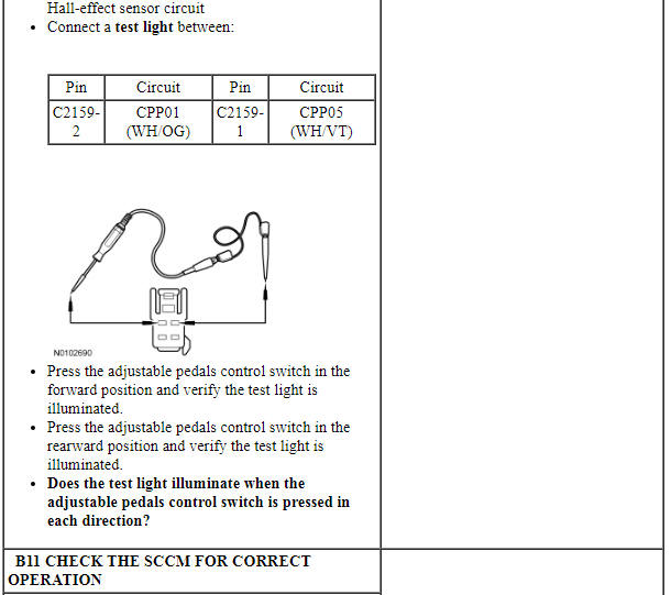
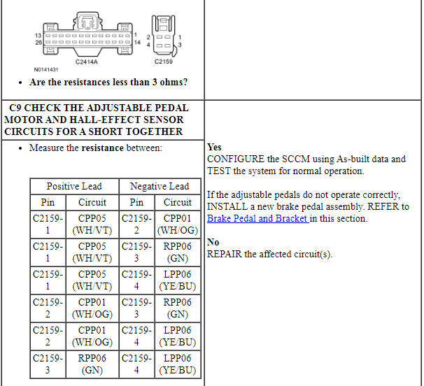
PINPOINT TEST C: THE ADJUSTABLE PEDALS ARE INOPERATIVE OR DO NOT OPERATE CORRECTLY - USING THE MEMORY SET SWITCH OR THE RKE TRANSMITTER
REMOVAL AND INSTALLATION
Brake Pedal and Bracket
NOTE: Fixed pedal assembly shown, adjustable pedal assembly similar.
- If equipped with adjustable pedals, make sure they are in the full forward position.
- Remove the steering column. For additional information, refer to Section 211-04.
- Disconnect the accelerator pedal sensor electrical connector, the adjustable pedal motor electrical connector (if equipped) and detach the wire harness from the brake pedal assembly.
- NOTICE: Do not service the brake pedal or brake booster
without first removing the stoplamp switch. The switch must be removed with
the brake pedal in the at-rest position. The switch plunger must be
compressed for the switch to rotate in the bracket. Attempting to remove the
switch when the plunger is extended (during pedal apply) will result in
damage to the switch.
Remove the stoplamp switch. For additional information, refer to Section 417-01.
- NOTE: The booster push rod clevis locking pin is a one-time use
only part. Any time the pin is removed, a new one must be installed.
NOTE: An 11 mm, 12-point socket or wrench can be used to compress the 2 tabs on the locking pin.
Remove and discard the booster push rod locking pin.
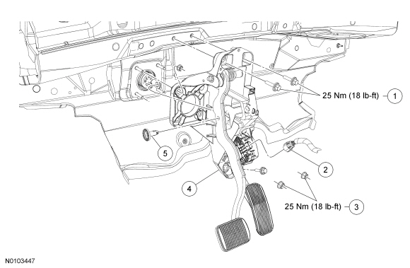
- Remove the 4 brake booster nuts.
- To install, tighten to 25 Nm (18 lb-ft).
- Position the brake booster forward enough to allow the brake booster studs to clear the brake pedal assembly.
- Remove the lower brake pedal bracket bolt, under the accelerator pedal,
from the brake pedal bracket assembly.
- To install, tighten to 25 Nm (18 lb-ft).
- Remove the upper 2 brake pedal bracket bolts from the brake pedal
bracket assembly.
- To install, tighten to 25 Nm (18 lb-ft).
- Disconnect the vehicle electrical harness locators and remove the brake pedal bracket assembly from the vehicle.
- NOTICE: Do not press, pull or otherwise move the brake pedal
while installing the stoplamp switch. The switch must be installed with the
booster push rod attached to the brake pedal and with the brake pedal in the
at-rest position. Installing the switch with the brake pedal in any other
position will result in incorrect adjustment and may damage the switch.
To install, reverse the removal procedure.
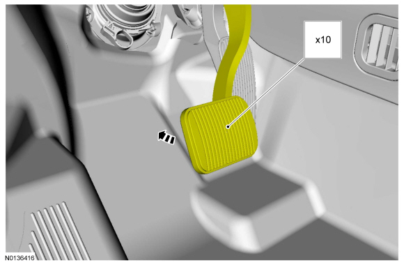
Adjustable Pedals Control Switch
NOTE: Steering wheel removed for clarity.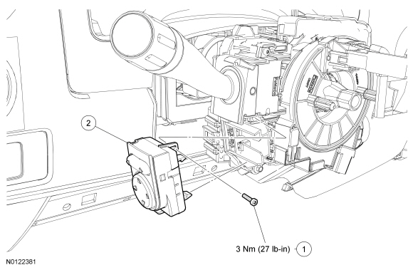
Removal and Installation
NOTE: Turn the steering wheel 90 degrees to the left to access the adjustable pedals control switch screws.
- Remove the steering column shrouds. For additional information, refer to Section 211-04.
- Remove the adjustable pedals control switch screw.
- To install, tighten to 3 Nm (27 lb-in).
- Using a suitable tool (such as a pocket screwdriver), carefully disengage the control switch locking tabs one at a time, then remove the adjustable pedals control switch.
- To install, reverse the removal procedure.
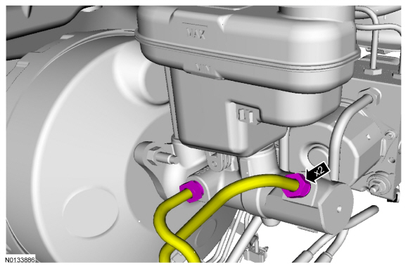
Brake Master Cylinder
Material
Removal
WARNING: Before beginning any service procedure in this section, refer to Safety Warnings in Section 100-00. Failure to follow this instruction may result in serious personal injury.
NOTICE: Do not spill brake fluid on painted or plastic surfaces or damage to the surface may occur. If brake fluid is spilled onto a painted or plastic surface, immediately wash the surface with water.
NOTE: Removal steps in this procedure may contain installation instructions.
- Remove the battery. For additional information, refer to Section 414-01.
- Remove the air cleaner outlet pipe. For additional information, refer to Section 303-12.
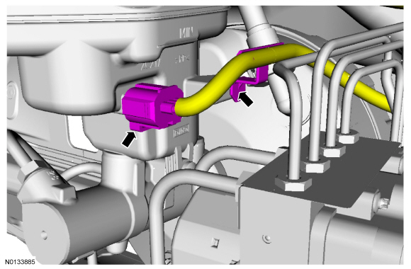
- NOTE: The brake tubes must be installed in the same position and
orientation as removed.
- Cap the brake tubes and plug the master cylinder ports.
- To install, tighten to 23 Nm (17 lb-ft).
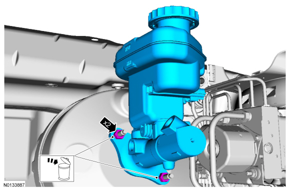
- NOTE: Make sure that the master cylinder-to-booster seal is
removed with the master cylinder.
Discard the specified component. Follow local disposal regulations.
- To install, tighten the new nuts to 20 Nm (177 lb-in).
Installation
- To install, reverse the removal procedure.
- Bleed the brake system. For additional information, refer to Section 206-00.
 Parking Brake and Actuation
SPECIFICATIONS
Torque Specifications
DESCRIPTION AND OPERATION
Parking Brake
The parking brake system consists of the following components:
Parking brake control and front cable assembly
Rear park ...
 Power Brake Actuation
SPECIFICATIONS
Torque Specifications
DESCRIPTION AND OPERATION
Brake Booster
The power brake actuation system includes a vacuum sorce (engine manifold or
vacuum pump), vacuum assisted brake booster, ...
Other materials:
Specifications, Description and Operation, General Procedures
SPECIFICATIONS
Material
General Specifications
Torque Specifications
a Tighten to 10 Nm (89 lb-in) plus an additional 720 degrees.
b Tighten to 16 Nm (142 lb-in) plus an additional 180 degrees.
c Refer to the procedure in this section.
d Tighten to 5 Nm (44 lb-in) plus ...
Diagnosis and Testing
Roof Opening Panel
Special Tool(s)
Principles of Operation
Roof Opening Panel
The roof opening panel assembly uses an integrated motor and module to
operate the roof opening panel. The roof opening panel motor and module are
installed new as an assembly. The roof opening panel is an electronicall ...
Locking and unlocking
You can use the power door lock control or the remote control to lock
and unlock your vehicle.
Power Door Locks
The power door lock control is located on the driver and front passenger
door panels.
A. Unlock
B. Lock
Remote Control
You can use the remote control anytime your vehicle is not ...
