SPECIFICATIONS
Torque Specifications
REMOVAL AND INSTALLATION
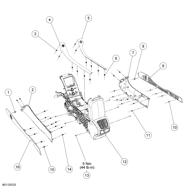
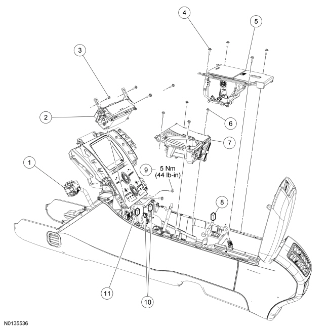
Instrument Panel - Exploded View
Instrument Panel Trim Panel and Fasteners
Instrument Panel Finish and Trim Panels
Instrument Panel Upper Section
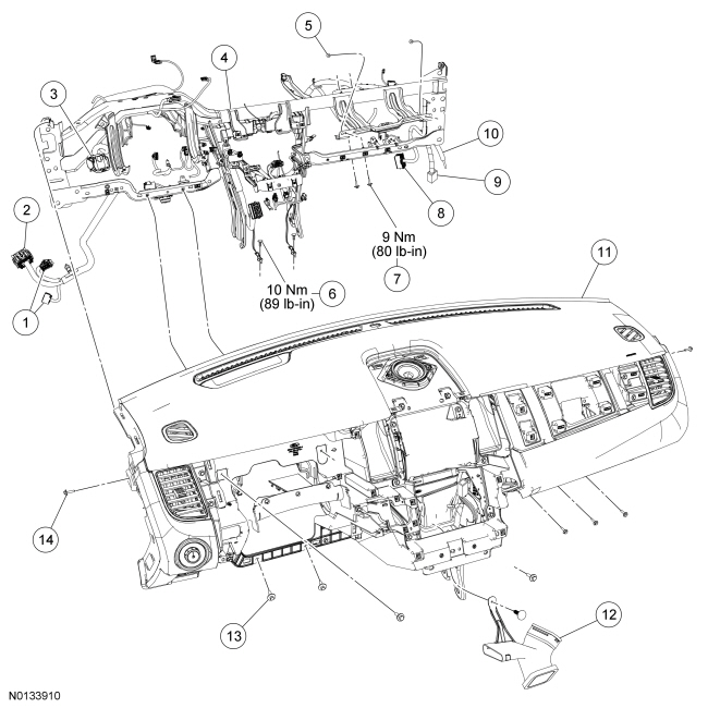
Glove Compartment
- For additional information, refer to the procedures in this section.
Instrument Panel
Removal
All vehicles
- Rotate the steering wheel until the front wheels are in the straight-ahead position.
- Drain the coolant. For additional information, refer to Section 303-03.
- Recover the refrigerant. For additional information, refer to Section 412-00.
- Remove the wiper mounting arm and pivot shaft assembly.
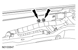
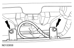
- Remove the 2 LH instrument panel upper cowl bolts.
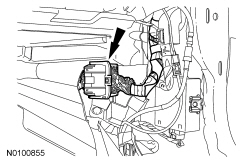
- Remove the PCM. For additional information, refer to Section 303-14.
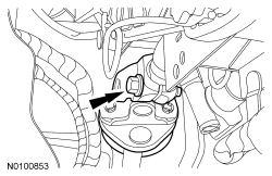
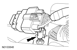
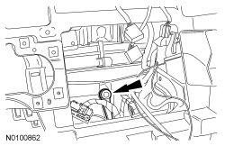
- Remove the wire harness retainer from the PCM bracket stud.

- Remove the 3 nuts and the PCM bracket.

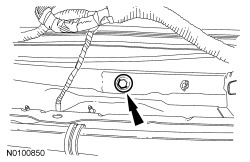
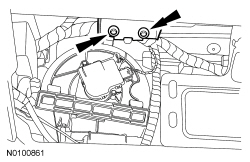
- Remove the RH instrument panel upper cowl bolt.
Vehicles with 2.0L engines
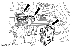
- Remove the upper engine cover.
- Lift up the engine cover, releasing the cover from the 3 cover retainers.
Vehicles with 3.5L engines
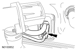
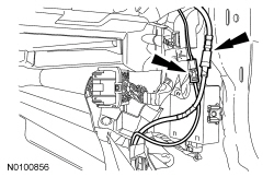
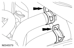
- Remove the vacuum hose clips from the strut tower cross brace.
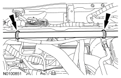
- Remove the strut tower cross brace.
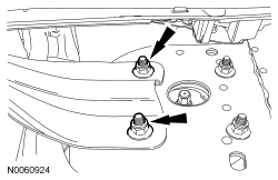
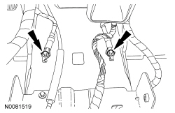
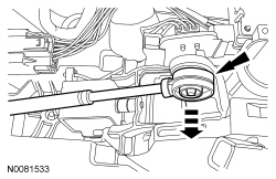
- NOTE: LH side shown, RH side similar.
Remove the LH and RH strut upper mount inboard nuts.
- NOTE: LH side shown, RH side similar.
All vehicles
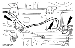
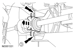
- Remove the heater hoses from the heater core.

- Remove the Thermostatic Expansion Valve (TXV) manifold nut and
the TXV manifold.
- Discard the O-ring seals.
- Remove the steering wheel. For additional information, refer to Section 211-04.
- Remove the front seats. For additional information, refer to Section 501-10.
Police vehicles without floor console
- Remove the lower center insturment panel finsh panel.
- Remove the LH and RH center instrument panel side panels.
All vehicles
- Remove the floor console. For additional information, refer to Console - Floor.
- Remove the LH and RH A-pillar trim panels. For additional information, refer to Section 501-05.
- Remove the LH and RH scuff plate trim panels. For additional information, refer to Section 501-05.
- Position aside the LH and RH door opening weatherstrips.
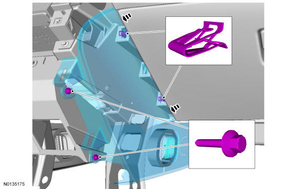
- Remove the LH and RH instrument panel side finish panels.
- Pull the sides of the instrument panel side finish panels away from the instrument panel to release the retaining tabs.
- Remove and discard the steering column shaft-to-steering column bolt.
- Separate the steering column shaft from the steering column.
- Disconnect the instrument panel upper LH bulkhead electrical connector.

- Disconnect the 2 Smart Junction Box (SJB) lower electrical connectors and instrument panel lower LH bulkhead electrical connector.
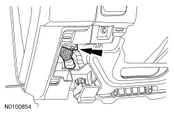
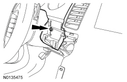
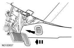
- Remove the hood release handle bolt and position the hood release handle aside.
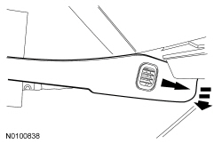
- Remove the driver footrest pad.
- Remove the 2 pin-type retainers.

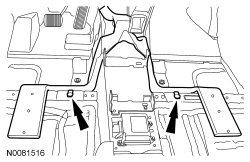
- NOTICE: To avoid damaging the carpet with coolant when the
instrument panel is removed, the carpet must be removed.
Remove the LH and RH front carpet sections.
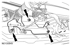
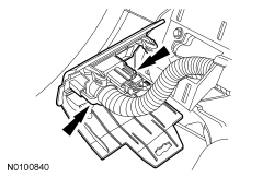
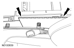
- Remove the 2 pin-type retainers.
- Remove the 2 pin-type retainers and the rear footwell duct.
- Disconnect the instrument panel RH bulkhead electrical connector.
- Disconnect the antenna cable and the satellite radio antenna connector, if equipped.
- Remove the 2 bolts and the ground wires from the floor pan tunnel.
- Disconnect the Restraints Control Module (RCM) small electrical connector and detach the 2 wire harness pin-type retainers.

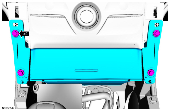
- Remove the 4 instrument panel center support bracket bolts.
- NOTICE: To avoid damaging the instrument panel, an assistant
is required to support the instrument panel when carrying out this step.
NOTE: Remove the bolts from one side completely and support the instrument panel before removing the bolts from the opposite side.
Remove the 6 instrument panel side bolts.
- NOTICE: Make sure that all electrical connectors and wiring
are not hindered before removing the instrument panel or damage to the
components may occur.
NOTICE: To avoid damaging the instrument panel, an assistant is required when carrying out this step.
NOTICE: Make sure not to damage the RH front door trim panel or the instrument panel when removing the instrument panel from the vehicle.
NOTICE: To avoid damage to the instrument panel, place the instrument panel on a covered bench upside-down.
Remove the instrument panel from the vehicle.- Rotate the instrument panel face down and remove through the RH front door opening.
Installation
All vehicles
- NOTICE: To avoid damage to the instrument panel, an assistant
is required when positioning the instrument panel to the vehicle.
NOTICE: Make sure not to damage the RH front door trim panel or the instrument panel when installing the instrument panel into the vehicle.
NOTICE: Make sure that all electrical connectors and wiring are correctly routed when installing the instrument panel or damage to the components may occur.
Install the instrument panel into the vehicle through the RH front door opening.
- Install, but do not tighten the 6 instrument panel side bolts.
- Install, but do not tighten the 4 instrument panel center support bolts.
- Install, but do not tighten the 3 instrument panel upper cowl bolts.
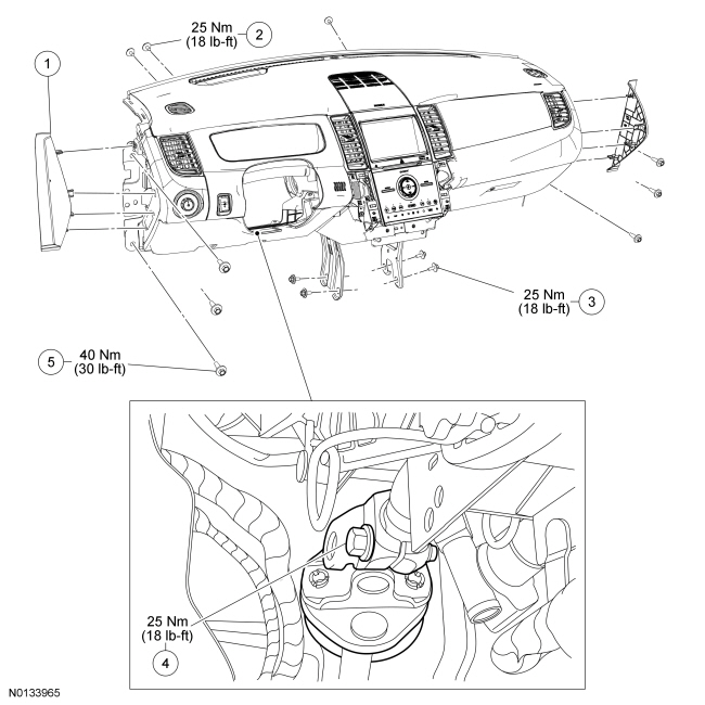
- Tighten the 6 instrument panel side bolts.
- Tighten to 40 Nm (30 lb-ft).
- Tighten the 4 instrument panel center support bracket bolts.
- Tighten to 25 Nm (18 lb-ft).
- Tighten the 3 instrument panel upper cowl bolts.
- Tighten to 25 Nm (18 lb-ft).
- Connect the small RCM electrical connector and attach the 2 wire harness pin-type retainers.
- Install the ground wires and the 2 bolts to the floor pan tunnel.
- Tighten to 10 Nm (89 lb-in).

- Connect the antenna cable and the satellite radio connector, if equipped.

- Connect the instrument panel RH bulkhead electrical connector.

- Install the rear footwell duct and the 2 pin-type retainers.

- Install the LH and RH front carpet sections.
- Install the 2 pin-type retainers.
- Install the driver footrest pad.
- Install the 2 pin-type retainers.
- Install the hood release handle.
- Install and tighten the hood release handle bolt.
- Connect the 2 SJB electrical connectors and instrument panel lower LH bulkhead electrical connector.

- Connect the instrument panel upper LH bulkhead electrical connector.
- Install the steering column shaft to the steering column.
- Install a new steering column shaft-to-steering column bolt.
- Tighten to 25 Nm (18 lb-ft).

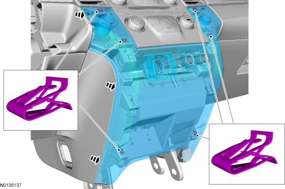
- Install the LH and RH instrument panel side finish panels.
- Make sure to align the instrument panel side finish panels retaining clips to the holes in the instrument panel.
- Position the weatherstrips.
- Install the LH and RH scuff plate trim panels.
- Make sure to align the scuff plate trim panel retaining clips to the retaining clip holes in the body.
- Install the LH and RH A-pillar trim panels.
Police vehicles without floor console
- Install the lower center insturment panel finsh panel.

- Install the LH and RH center instrument panel side panels.
- Tighten to 3 Nm (27 lb-in).

All vehicles
- Install the floor console.
- Install the front seats.
- Install the steering wheel.
- Install the TXV manifold.
- Install new O-ring seals.
- Install and tighten the TXV manifold and nut.
- Tighten to 8 Nm (71 lb-in).

- Connect the heater hoses to the heater core.
- Install the PCM bracket.
- Install and tighten the 3 PCM bracket nuts.
- Install the wire harness retainer onto the PCM bracket stud.
- Install the PCM. For additional information, refer to Section 303-14.
Vehicles with 3.5L engines
- Install the strut tower cross brace.
- NOTE: LH side shown, RH side similar.
Install the LH and RH strut upper mount nuts.
- Tighten to 30 Nm (22 lb-ft).
- NOTE: LH side shown, RH side similar.

- Install the vacuum hose clips onto the strut tower cross brace.

Vehicles with 2.0L engines,
- Install the upper engine cover.
- Make sure to align the 3 engine cover holes to the retaining points.
- Press down on the engine cover to secure.
All vehicles
- Install the wiper mounting arm and pivot shaft assembly. For additional information, refer to Section 501-16.
- Charge the refrigerant system. For additional information, refer to Section 412-00.
- Fill the cooling system. For additional information, refer to Section 303-03.
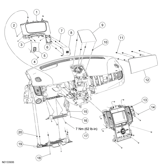
Instrument Panel Upper Section
Removal and Installation
All vehicles
- Remove the floor console. For additional information, refer to Console - Floor in this section.
Police vehicles without floor console
- Remove the lower center insturment panel finsh panel.

- Remove the LH and RH center instrument panel side panels.

All vehicles
- Remove the LH and RH scuff plate trim panels. For additional information, refer to Section 501-05.
- Remove the LH and RH lower cowl panel side trim.
- Position aside the LH and RH door opening weatherstrips.
- Remove the LH and RH A-pillar trim panels. For additional information, refer to Section 501-05.
- Remove the LH and RH instrument panel side finish panels.
- Pull the sides of the instrument panel side finish panels away from the instrument panel to release the retaining tabs.
- Tilt the steering wheel to the full downward and fully extended positions.
- Remove the steering wheel. For additional information, refer to Section 211-04.
- Remove the steering column shrouds. For additional Information refer to Section 211-04
-
- To Install, tighten to 3 Nm (27 lb-in).
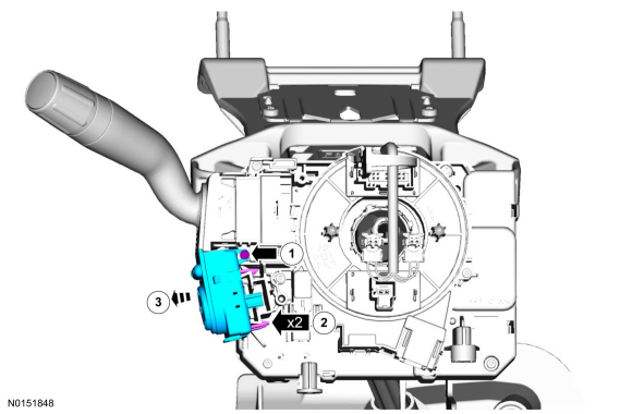
- Remove the steering column multifunction switch. For additional information, refer to Section 211-05.
- Remove the Instrument Cluster (IC). For additional information, refer to Section 413-01.
- Unclip and remove the Global Positioning System Module (GPSM).
- Disconnect the connector.
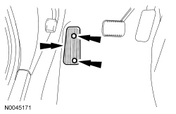
- Remove the instrument panel reinforcement plate.
- Remove the 2 instrument panel reinforcement plate screws.
- To install, tighten to 3 Nm (27 lb-in).
- Remove the 2 instrument panel reinforcement plate bolts.
- To install, tighten to 7 Nm (62 lb-in).
- Remove the 2 instrument panel reinforcement plate screws.
- From behind the instrument panel, disconnect the headlamp switch electrical connector.
- Remove the center instrument panel finish panel. For additional information, refer to Instrument Panel Finish Panel - Center.
- NOTE: Front Display Interface Module (FDIM) with navigation
shown, without navigation similar.
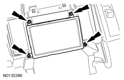
Remove FDIM.
- Remove the 4 FDIM screws.
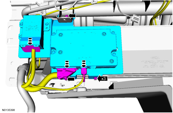
- Disconnect the 2 Accessory Protocol Interface Module (APIM) electrical connectors.

- Remove the HVAC module. For additional Information, refer to Section 412-01.
- Remove the 2 Audio Front Control Module (ACM) upper bracket screws.
- If equipped, remove the instrument panel center speaker.
- Remove the 2 instrument panel center speaker screws.
- Disconnect the electrical connector.
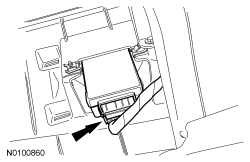
- Remove the light sensor.
- Disconnect the electrical connector.
- NOTICE: When prying on a component, a non-marring tool must be
used or damage to the component may occur.
Remove the defroster grille.
- With a non-marring tool, pry the defroster grille upward releasing the 7 clips from the instrument panel. Disconnect the electrical connector(s).
- Remove the bolt and position aside the hood release handle.
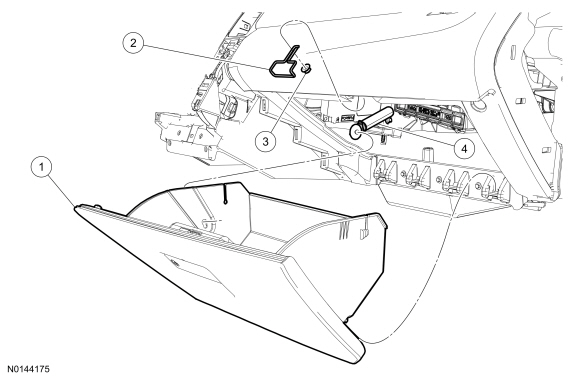
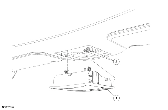
- Remove the glove compartment.
- Open the glove compartment.
- Disconnect the dampener linkage from the glove compartment.
- Press the sides of the glove compartment inward.
- Lower the door and release the glove compartment hinge from the instrument panel.
- NOTE: The heated steering wheel module is located behind the RH
instrument panel finish panel.
If equipped with heated steering, disconnect the heated steering wheel module electrical connector through the glove compartment opening.

- Disconnect the 3 passenger air bag electrical connectors.
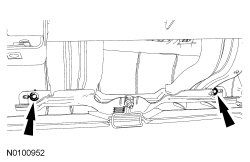
- Through the glove compartment opening, remove the 2 passenger side air
bag-to-crossbeam bolts.
- To install, tighten to 9 Nm (80 lb-in).
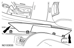
- Through and above the glove compartment opening, remove the 2 instrument panel rear screws.

- Remove the console duct Y adapter.
- Through the center of the instrument panel opening, remove the console duct Y adapter pin-type retainer.
- NOTE: To aid in the installation of the instrument panel upper
section, mark the locations of the instrument panel upper section screws.
Remove the 9 instrument panel front and side screws.
- Remove the 2 instrument panel side screws.
- Remove the 2 instrument panel front screws located near the Data Link Connector (DLC).
- Remove the 2 instrument panel front screws located in the instrument cluster opening area.
- Remove the 3 instrument panel front screws located in the glove compartment hinge area.
- NOTICE: To avoid damaging the instrument panel upper section,
the aid of an assistant is required when carrying out this step.
NOTICE: Make sure that all electrical connectors and wiring are not hindered before removing the instrument panel upper section or damage to the components may occur.
Remove the instrument panel upper section.
- NOTICE: To avoid damaging the instrument panel upper section,
the aid of an assistant is required when positioning the instrument panel to
the vehicle.
NOTICE: Make sure that all electrical connectors and wiring are correctly routed when installing the instrument panel upper section or damage to the components may occur.
To install, reverse the removal procedure.- Transfer parts as needed.
- To install, make sure to align the retaining clips to the adjacent retaining clip holes.
- Attach a suitable wire to the light sensor connector to assist in routing the connector through the hole in the upper instrument panel during installation.
In-Vehicle Crossbeam
Removal and Installation
All vehicles
- Remove the heater core and evaporator core housing. For additional information, refer to Section 412-01.
- Remove the steering column multifunction switch. For additional information, refer to Section 211-05.
- Remove the Instrument Panel Cluster (IPC). For additional information, refer to Section 413-01.
- Remove the instrument panel reinforcement plate.
- Remove the 2 instrument panel reinforcement plate screws.
- To install, tighten to 3 Nm (27 lb-in).
- Remove the 2 instrument panel reinforcement plate bolts.
- To install, tighten to 7 Nm (62 lb-in).
- Remove the 2 instrument panel reinforcement plate screws.
- From behind the instrument panel, disconnect the headlamp switch electrical connector.
- Depending on vehicle option content, remove the Front Control/Display Interface Module (FCDIM) or the Front Controls Interface Module (FCIM). Refer to the appropriate section in Group 415 for the procedure.
- NOTE: Front Display Interface Module (FDIM) with navigation
shown, without navigation similar.
Remove the FDIM.
- Remove the 4 FDIM screws.
- Disconnect the 2 electrical connectors.
- Remove the Audio Front Control Module (ACM). For additional information, refer to Section 415-00A.

- If equipped, remove the instrument panel center speaker.
- Remove the 2 instrument panel center speaker screws.
- Disconnect the electrical connector.
- NOTICE: When prying on a component, a non-marring tool must be
used or damage to the component may occur.
Remove the defroster grille.
- With a non-marring tool, pry the defroster grille upward releasing the 7 clips from the instrument panel. Disconnect the electrical connector(s).
- Remove the glove compartment.
- Open the glove compartment.
- Disconnect the glove compartment dampener linkage from the glove compartment.
- Press the sides of the glove compartment inward.
- Lower the door and release the glove compartment hinge from the instrument panel.
- NOTE: The ambient light module is located behind the RH
instrument panel finish panel.
If equipped with ambient lighting, disconnect the ambient light module electrical connector through the glove compartment opening.
Police vehicles
- Disconnect the 3 electrical connectors and remove the Accessory Protocol
Interface Module (APIM) bracket.
- To install, tighten to 3 Nm (27 lb-in).
All vehicles
- Disconnect the 2 passenger air bag electrical connectors.
- Through the glove compartment opening, remove the 2 passenger side air
bag-to-crossbeam bolts.
- To install, tighten to 9 Nm (80 lb-in).

- Through and above the glove compartment opening, remove the 2 instrument panel rear screws.
- NOTE: To aid in the installation of the instrument panel upper
section, mark the locations of the instrument panel screws.
Remove the 9 instrument panel front and side screws.
- Remove the 2 instrument panel side screws.
- Remove the 2 instrument panel front screws located near the Data Link Connector (DLC).
- Remove the 2 instrument panel front screws located in the IPC opening area.
- Remove the 3 instrument panel front screws located in the glove compartment hinge area.
- NOTICE: Make sure that all electrical connectors and wiring
are not hindered before removing the in-vehicle crossbeam or damage to the
components may occur.
Remove the in-vehicle crossbeam.
- NOTICE: Make sure that all electrical connectors and wiring
are correctly routed when installing the in-vehicle crossbeam or damage to
the components may occur.
To install, reverse the removal procedure.
- Transfer parts as needed.
- To install, make sure to align the retaining clips to the adjacent retaining clip holes.
Instrument Panel Finish Panel - Center
Removal and Installation
All vehicles
NOTE: The ignition must be OFF if disconnecting the FCIM indicator electrical connector. Otherwise, DTC will set and must be cleared before releasing the vehicle.
- Remove the instrument cluster finish panel. For additional information, refer to Instrument Cluster Finish Panel.
- If equipped, remove the floor console RH finish moulding.
- Lift up the rear of the floor console finish moulding to release the retaining clips from the floor console.
- Pull the floor console finish moulding toward the rear of the vehicle to release the retaining clips from the center instrument finish panel.
- Disconnect the trunk release switch electrical connector.
- Remove the RH instrument panel finish panel. For additional information, refer to Instrument Panel Finish Panel - RH.
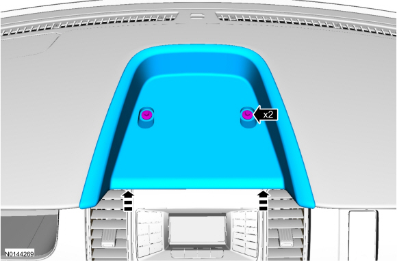
NOTICE: When prying on a component, a non-marring tool must be used or damage to the component may occur.
NOTICE: The instrument panel upper cover retaining clips must be released one corner at a time. Failure to do so may cause damage to the instrument panel upper cover.
- Remove the instrument panel upper cover. With a non-marring tool, lift the corners of the instrument panel upper cover upward to release the retaining clips.
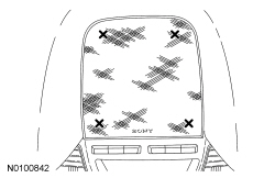
Police vehicles
- Remove the 2 fasteners and the instrument panel tray.
All vehicles
- Remove the selector lever trim panel. For additional information, refer to Section 307-05.
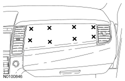
- If equipped, remove the front media bin/storage compartment in the
following sequence.
- Remove the 4 front media bin screws and lift the front media bin away from the floor console.
- Disconnect the electrical connector(s).

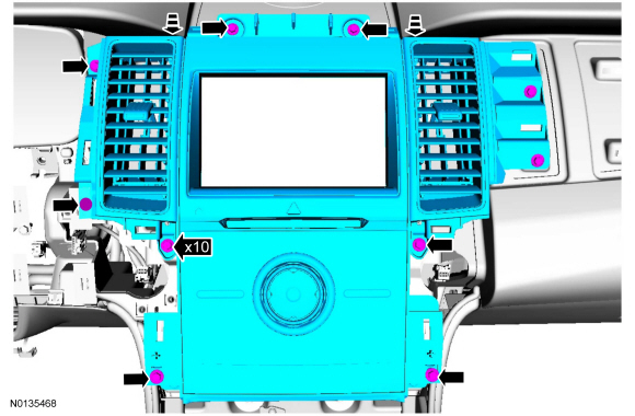
NOTE: Center instrument panel finish panel with Sony sound shown, all others similar.
- Remove instrument panel finish panel.
- Disconnect the instrument panel finish panel electrical connectors.
- To install, tighten to 3 Nm (27 lb-in).
- To install, reverse the removal procedure and perform prove out after installation.
Instrument Panel Finish Panel - RH
Removal and Installation
NOTICE: When prying on a component, a non-marring tool must be used or damage to the component may occur.
NOTICE: The RH instrument panel finish panel must be removed in the following sequence, failure to may cause damage to the RH instrument panel finish panel.
- Remove the RH instrument panel finish panel in the following sequence.
- With a non-marring tool, pry the lower LH corner of the RH instrument panel finish panel toward the rear of the vehicle to release the retaining clip.
- Continue to release the next lower retaining clip, followed by the others prying toward the rear of the vehicle.
- Release the additional upper retaining clips, starting with a corner and continuing to release the next upper retaining clip, followed the others by prying toward the rear of the vehicle.
- To install, reverse the removal procedure.
- To install, make sure to align the trim panel retaining clips to the retaining clip holes in the instrument panel.
Instrument Panel Finish Panel - LH
Removal and Installation
- Remove the steering column opening trim panel in the following sequence.
- Remove the 2 steering column opening trim panel screws.
- Pull the steering column opening trim panel down toward the floor of the vehicle to release the retaining clips.
- Remove the LH instrument panel finish panel screw.
NOTICE: Do not pry lower than the LH instrument panel finish panel or damage to the instrument panel cluster finish panel may occur.
NOTICE: When prying on a component, a non-marring tool must be used or damage to the component may occur.
- Remove the LH instrument panel finish panel in the following sequence.
- With a non-marring tool, pry toward the rear of the vehicle to release the 2 retaining clips.
- If equipped, disconnect the electrical connectors.
- To install, reverse the removal procedure.
- To install, make sure to align the trim panel retaining clips to the retaining clip holes in the instrument panel.
Instrument Cluster Finish Panel
Removal and Installation
- Tilt the steering wheel to the full downward and fully extended positions.
- Remove the LH instrument panel finish panel. For additional information, refer to Instrument Panel Finish Panel - LH.
- If equipped, remove the floor console LH finish moulding.
- Lift up the rear of the floor console finish moulding to release the retaining clips from the floor console.
- Pull the floor console finish moulding toward the rear of the vehicle to release from the retaining clips from the center instrument finish panel.
- Disconnect the start/stop button electrical connector, if equipped.
- NOTE: Police vehicles are not equipped with tube.
Remove the in-vehicle temperature sensor cover.
- Pull the cover toward the rear of the vehicle releasing the cover retaining clips from the instrument panel cluster finish panel.
- Press the 2 release tabs to remove the in-vehicle temperature sensor from the cover.
- Remove the instrument cluster finish panel screw.
NOTICE: When prying on a component, a non-marring tool must be used or damage to the component may occur.
- Remove instrument cluster finish panel.
- With a non-marring tool, pry the lower LH corner of the instrument cluster finish panel toward the rear of the vehicle to release the retaining clips.
- Rotate the instrument cluster finish panel from the bottom upward to releasing the upper retaining clips.
- Continue to rotate instrument cluster finish panel to remove from the instrument panel.
- To install, reverse the removal procedure.
- To install, make sure to align the trim panel retaining clips to the retaining clip holes in the instrument panel.
Power Point
Special Tool(s)
Removal
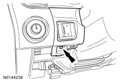
NOTE: Power point cover may differ depending on location.
- Open the power point cover.
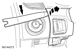
- Install the Power Point Socket Remover in one of the power point socket slots.
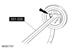
- Position the Power Point Socket Remover so that it engages in the adjacent slot.
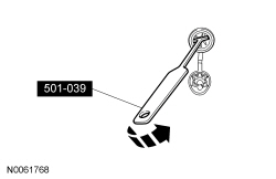
- Using the Power Point Socket Remover, pull the power point socket out of the retainer.
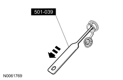
- Disconnect the electrical connector.
Installation
- Connect the electrical connector.
- Slide the power point socket into the retainer.
Console - Floor
Trim Panels, Mouldings And Fasteners
NOTE: Floor console with navigation shown, floor console without navigation similar.
Trim Panels And Fasteners
NOTE: Floor console with navigation shown, floor console without navigation similar.
Removal and Installation
- Place the selector lever in the NEUTRAL position.
- Position the front seats to the full rearward and downward positions.
- Pull the middle and rear of the floor console LH and RH lower trim panels outward to release the retaining clips.
- NOTICE: Damage to the floor console upper trim panels may
occur if cardboard is not used to remove the floor console lower trim
panels.
NOTE: Floor console LH lower trim panel shown, floor console RH lower trim panel similar.
Position a piece of cardboard between the floor console LH and RH lower trim panels and floor console.
- Remove the floor console LH lower trim panel.
- Push the floor console LH lower trim panel toward the front of the vehicle to detach the trim panel from the pin-type retainer.
- Remove the floor console RH lower trim panel.
- Pull the floor console RH lower trim panel down toward the floor of the vehicle to detach the trim panel from the pin-type retainer.
- Position the front seats forward.
- Remove the 2 floor console lower rear screws.
- Position the front seats rearward.
- Remove the steering column opening trim panel.
- Remove the 2 steering column opening trim panel screws.
- Pull the steering column opening trim panel down toward the floor of the vehicle to release the retaining clips.
- Remove the floor console LH and RH finish mouldings.
- Lift up the rear of the floor console finish mouldings to release the retaining clips from the floor console.
- Pull the floor console finish mouldings toward the rear of the vehicle to release the retaining clips from the center instrument finish panel.
- Disconnect the trunk release switch and start/stop button electrical connector, if equipped.
NOTICE: Damage to the floor console may occur if cardboard is not used to remove the floor console upper trim panel.
NOTE: Floor console LH upper trim panel shown, floor console RH upper trim panel similar.
- Remove the floor console LH upper trim panel.
- Pull the rear of the floor console LH upper trim panel away from the floor console, releasing the retaining clips.
- Position a piece of cardboard between the floor console LH upper trim panel and floor console.
- Pull the floor console LH upper trim panel toward the rear of the vehicle to release the retaining clips from the instrument panel.
- Remove the 2 pushpin carpet retainers, 4 floor console lower front and middle screws.
- Remove the selector lever bezel. For additional information, refer to Section 307-05.
- Remove the media bin/storage compartment.
- Disconnect the electrical connector(s).
- To install, tighten to 3 Nm (27 lb-in).
- Disconnect the floor console bulkhead electrical connector.
- Detach the wire harness pin-type retainer from the floor console.
- Remove the 2 floor console upper bolts.
- Disconnect the selector lever cable from the selector lever.
- Remove the selector cable from the selector lever cable bracket.
- Release the 2 selector cable retaining tabs and pull the selector lever upward.
- Remove the floor console.
- Pull the floor console rearward to release the retaining clips from the instrument panel.
- To install, reverse the removal procedure.
- To install, make sure to align the retaining clips to the adjacent retaining clip holes.
Console - Overhead
- Remove the overhead console.
- Pull the rear of the overhead console downward and then rearward.
- Disconnect the electrical connectors.
- To install, reverse the removal procedure.
 Removal and Installation
Glass, Frames and Mechanisms - Exploded View, Front Door
For additional information, refer to the procedures in this section.
Window Glass - Front Door
Removal and Installation
NOTE: The pow ...

Other materials:
Diagnostic Methods
Effective Diagnostic Techniques
NOTE: Do not use this document in place of Ford-prescribed Symptom
Based Diagnostics or Workshop Manual diagnostics. Diagnostic Methods is intended
to provide Ford vehicle diagnostic information only for support of
Ford-prescribed diagnostics.
The following di ...
Using This Manual
Introduction
This manual describes and directs repair procedures specified by Ford Motor
Company for the vehicle. Critical health and safety precautions are included.
Anyone who deviates from these instructions risks compromising personal safety
or vehicle integrity.
SECTION CONTENT
This manual ...
Diagnosis and Testing
Safety Belt System
Principles of Operation
WARNING: All
safety belt components must be inspected and corrected as part of any collision
repair. Inspect all safety belt components as prescribed by Safety Belt
Inspection and Repair After a Collision found in Section 501-20A General
Procedure ...
