Engine
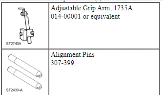
Special Tool(s)
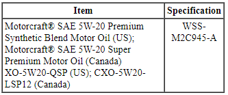
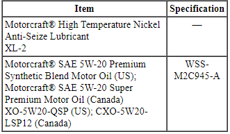
Material
All vehicles
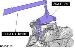
- Using the Floor Crane and Spreader Bar, align the transaxle to the engine.
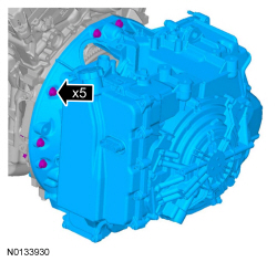
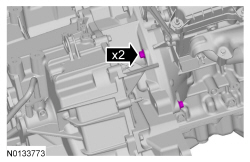
- Align the transaxle to the engine and install the 5 transaxle-to-engine
bolts.
- Tighten to 48 Nm (35 lb-ft).
- Install the 2 engine-to-transaxle bolts.
- Tighten to 48 Nm (35 lb-ft).
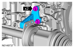
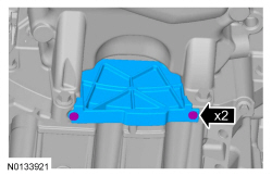
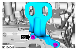
- Install the RH halfshaft support bracket and the 2 bolts.
- Tighten to 40 Nm (30 lb-ft).
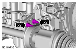
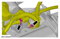
- Install the 2 intermediate shaft bracket studs and nuts.
- Tighten the studs to 10 Nm (89 lb-in).
- Tighten the nuts to 25 Nm (18 lb-ft).
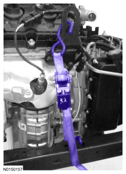
- NOTE: LH shown, RH similar.
Install the ratchet strap from the front subframe to the LH engine lift eye and from the rear of the subframe to the RH engine lift eye.

- Using the Floor Crane and Spreader Bar, install the powertrain and subframe as an assembly on the powertrain lift table.

- NOTE: LH shown, RH similar.
Remove the ratchet strap from the front subframe to the LH engine lift eye and from the rear of the subframe to the RH engine lift eye.
- Install the Adjustable Grip Arm.

- Install a ratchet strap from the front of the subframe under the powertrain lift table to the rear of the subframe, to secure the subframe to the powertrain lift table.
All-Wheel Drive (AWD) vehicles
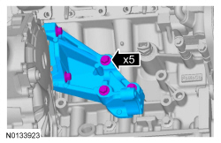
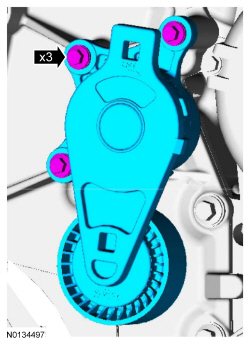
- Position the PTU support bracket in place and install the 5 bolts.
- Tighten to 70 Nm (52 lb-ft).
All vehicles
- Install 6 new RH exhaust manifold studs.
- Tighten to 12 Nm (106 lb-in).
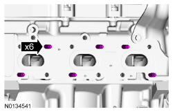
- NOTICE: Failure to tighten the exhaust manifold nuts to
specification a second time will cause the exhaust manifold to develop an
exhaust leak.
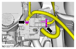
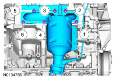
Using a new gasket, install the RH exhaust manifold and 6 new nuts. Tighten in 2 stages in the sequence shown:
- Stage 1: Tighten to 20 Nm (177 lb-in).
- Stage 2: Tighten to 25 Nm (18 lb-ft).

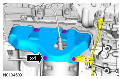
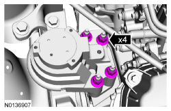
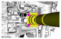
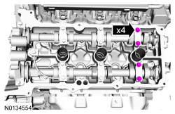
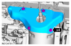
- Install the RH catalytic converter heat shield, Catalyst Monitor Sensor
(CMS) wiring harness bracket and the 4 bolts.
- Tighten to 10 Nm (89 lb-in).
- Connect the RH Heated Oxygen Sensor (HO2S) electrical connector.
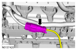
- Connect the RH CMS electrical connector.
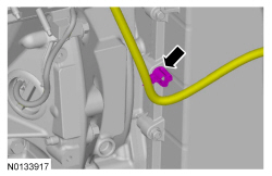
- Attach the transaxle control wire harness retainer to the transaxle stud bolt.
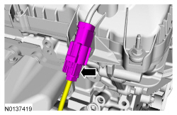
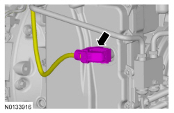
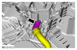
- Connect the transaxle control electrical connector.
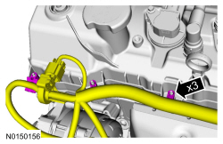
- Position the wiring harness and attach the 3 wiring harness retainer to the valve cover stud bolt.
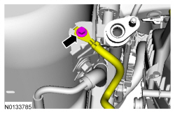
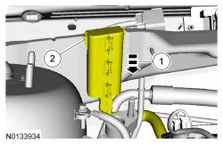
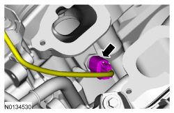
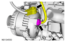
- Connect the generator B+ cable and install the nut.
- Tighten to 17 Nm (150 lb-in).
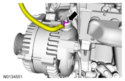
- Position back the generator B+ cable cover and connect the generator electrical connector.

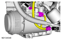
- Connect the 2 A/C compressor electrical connectors.
- Attach the A/C wiring harness retainer.
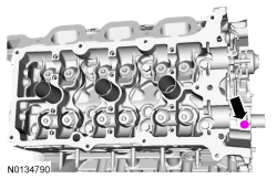
- Install the ground wire to the RH cylinder head and install the bolt.
- Tighten to 10 nm (89 lb-In).

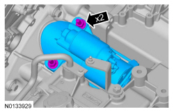
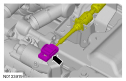
- Install the starter, the stud bolt and bolt.
- Tighten to 27 Nm (20 lb-ft).
- Connect the wiring harness retainer to the starter motor stud bolt.
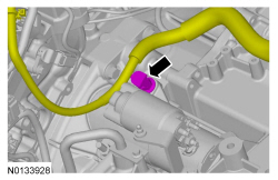
- Attach the starter wire terminals and install the 2 nuts.
- Tighten the B+ terminal nut to 12 Nm (106 lb-in).
- Tighten the S-terminal nut to 5 Nm (44 lb-in).
- Install the starter motor solenoid cover.
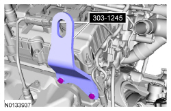
- Remove the Heavy Duty Floor Crane and Spreader Bar.

- Remove 303-1245 from the LH cylinder head.
- Raise the subframe and powertrain assembly into the vehicle.
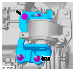
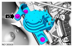
- Install the engine mount and the 3 bolts.
- Tighten to 90 Nm (66 lb-ft).

- Install the 4 engine mount nuts.
- Tighten to 63 Nm (46 lb-ft).
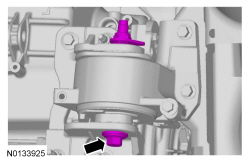
- Install the transaxle support insulator bracket, 3 nuts and the bolt.
- Tighten the transaxle support insulator bracket nuts to 63 Nm (46 lb-ft).
- Tighten the transaxle support insulator bolt to 80 Nm (59 lb-ft).
- Install the transaxle support insulator through bolt and nut.
- Tighten to 175 Nm (129 lb-ft).

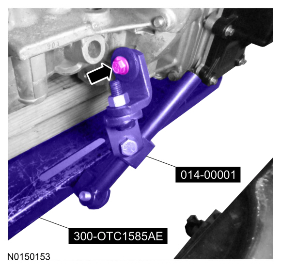
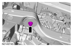
- NOTE: RH shown, LH similar.
Align the subframe and install the new front subframe bolts.
- Tighten to 200 Nm (148 lb-ft).

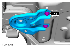
- NOTE: RH shown, LH similar.
Install the rear subframe brackets and the new subframe bracket-to-body bolts.
- Finger tight at this stage.

- NOTE: RH shown, LH similar.
Install the new subframe bracket bolts.
- Tighten to 150 Nm (111 lb-ft).
- NOTE: RH shown, LH similar.
Tighten the subframe bracket-to-body bolts to 55 Nm (41 lb-ft).

- Remove the ratchet strap from the front of the subframe to the rear of the subframe.
- Remove the Adjustable Grip Arm and the powertrain lift table.
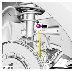
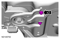
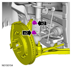
- NOTE: LH shown, RH similar.
Install the strut to the wheel knuckle and install the strut-to-wheel knuckle nuts and bolts.
- Tighten to 250 Nm (184 lb-ft).

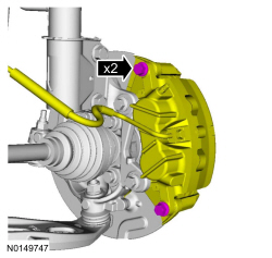
- NOTE: LH shown, RH similar.
Install the brake caliper and the guide pin bolts.
- 432 mm (17 in) brakes: Tighten to 72 Nm (53 lb-ft).
- 457 mm (18 in) brakes: Tighten to 75 Nm (55 lb-ft).

- NOTICE: Do not tighten the wheel hub nut with the vehicle on
the ground. The nut must be tightened to specification before the vehicle is
lowered onto the wheels. Wheel bearing damage will occur if the wheel
bearing is loaded with the weight of the vehicle applied.
NOTE: LH shown, RH similar.
NOTE: Apply the brake to keep the halfshaft from rotating.
Using the previously removed wheel hub nut, seat the LH and RH halfshafts.- Tighten to 350 Nm (258 lb-ft).
- Remove and discard the wheel hub nuts.
- NOTICE: The wheel hub nut contains a one time locking chemical
that is activated by the heat created when it is tightened. Install and
tighten the new wheel hub nut to specification within 5 minutes of starting
it on the threads. Always install a new wheel hub nut after loosening or
when not tightened within the specified time or damage to the components can
occur.
NOTE: LH shown, RH similar.
NOTE: Apply the brake to keep the halfshaft from rotating.
Install a new wheel hub nuts.- Tighten to 350 Nm (258 lb-ft).
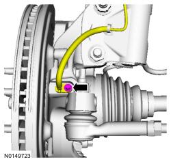
- NOTE: LH shown, RH similar.
Install the new upper stabilizer link nut.
- Tighten to 150 Nm (111 lb-ft).
- NOTE: LH shown, RH similar.
Install the wheel speed sensor and the bolt.
- Tighten to 15 Nm (133 lb-in).

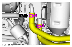
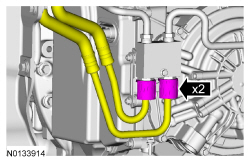
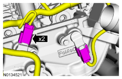
- Connect the transaxle cooler tubes and install the 2 secondary latches.

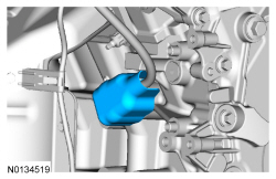
- If equipped, install the oil cooler hose retainer to the subframe.

- If equipped, connect the 2 oil cooler coolant hoses.
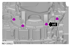
- Install the 4 oil pan-to-transaxle bolts.
- Tighten to 48 Nm (35 lb-ft).
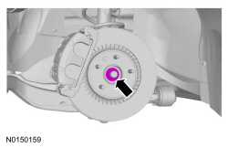
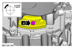
- Install 3 new torque converter bolts by rotating the crankshaft
clockwise.
- Tighten to 55 Nm (41 lb-ft).
- Install the inspection cover and the 2 fasteners.
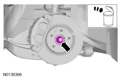
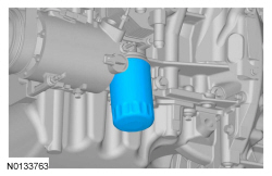
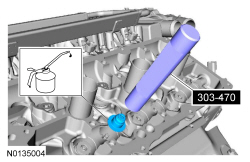
- NOTE: Do not lubricate the engine oil filter gasket with oil.
Install a new engine oil filter.
- Tighten to 5 Nm (44 lb-in) and then rotate an additional 180 degrees.

AWD vehicles
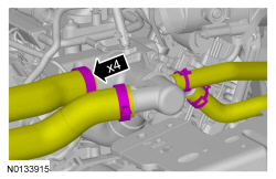
- Line up the index marks on the rear driveshaft to the index marks on
the PTU flange made during removal and install the 4 new bolts.
- Tighten to 70 Nm (52 lb-ft).
All vehicles
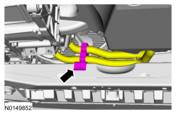
- Install the exhaust Y-pipe. For additional information, refer to Section 309-00.
- NOTICE: Do not allow the intermediate shaft to
rotate while it is disconnected from the gear or damage to the clockspring
may occur. If there is evidence that the intermediate shaft has rotated, the
clockspring must be removed and recentered. For additional information,
refer to Section 501-20B.
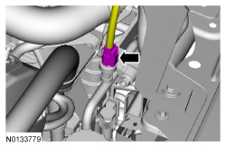
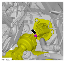
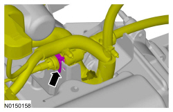
Align and connect the steering column shaft to the steering gear and install the bolt.
- Tighten to 20 Nm (177 lb-in).

- If equipped, attach the engine block heater harness to the radiator support.
- Attach the wiring harness pin-type retainer to the shift cable bracket and connect the transaxle control cable to the shift cable bracket.
- Connect the transaxle control cable to the control lever.
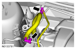
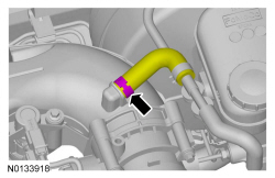
- Connect the upper radiator hose, lower radiator hose and 2 heater hoses to the thermostat housing.
- Install the ground wire to the RH shock tower and install the bolt.
- Tighten to 10 Nm (89 lb-in).
- Install the engine wiring harness retainer to the bulkhead.
- Slide the wiring harness in the bulkhead.
- Make sure the wiring harness retainer tab is below the bulkhead lip.

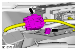
- Connect the engine harness electrical connector.
- Attach the wiring harness retainer.

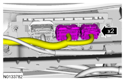
- Connect the 2 PCM electrical connectors.

- Connect the Evaporative Emission (EVAP) tube and the fuel supply tube quick connect coupling. For additional information, refer to Section 310-00.

- Connect the brake booster vacuum hose to the upper intake manifold.

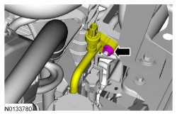
- Connect the degas bottle coolant hose to the engine coolant tube.
- Install the degas bottle. For additional information, refer to Section 303-03.
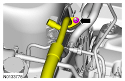
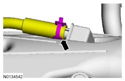
- Using a new O-ring seal and gasket seal, connect the upper A/C tube to
the condenser and install the nut.
- Tighten to 15 Nm (133 lb-in).

- Connect the A/C pressure switch electrical connector.
- Using a new O-ring seal and gasket seal, connect the A/C tube and
install the nut.
- Tighten to 15 Nm (133 lb-in).
- Install the accessory drive belt. For additional information, refer to Section 303-05.
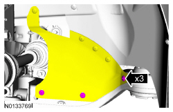
- Position the splash shield and install the 3 pin-type retainers.
- Install the front wheels and tires. For additional information, refer to Section 204-04.
- If equipped, install the skid plate and the 10 retainers.
- Tighten to 70 Nm (52 lb-ft).
- If equipped, install the underbody shield and attach the 4 retainers.
- Connect the engine wiring harness electrical connector.
- Install the ground wire cable and the retainer.
- Tighten to 10 Nm (89 lb-in).

- Connect the 2 battery feed cables to the positive battery terminal and
install the nut.
- Tighten to 5 Nm (44 lb-in).

- Install the battery tray. For additional information, refer to Section 414-01.
- Install the engine Air Cleaner (ACL) and ACL outlet pipe. For additional information, refer to Section 303-12.
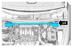
- Install the strut tower brace and the 4 nuts.
- Tighten to 35 Nm (26 lb-ft).
- Install the cowl panel grille. For additional information, refer to Section 501-02.
- Fill the engine with clean engine oil.
- Fill and bleed the cooling system. For additional information, refer to Section 303-03.
- Recharge the A/C system. For additional information, refer to Section 412-00.
- Perform the Misfire Monitor Neutral Profile Correction procedure, following the on-screen instructions.
Camshaft
Special Tool(s)
Material
RH camshafts
- NOTE: Coat the camshafts with clean engine oil prior to
installation.
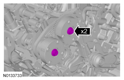
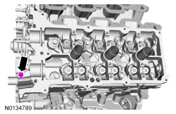
Position the camshafts onto the RH cylinder head in the neutral position as shown.
- NOTICE: The crankshaft must remain in the freewheeling
position (crankshaft dowel pin at 9 o'clock) until after the camshafts are
installed and the valve clearance is checked/adjusted. Do not turn the
crankshaft until instructed to do so. Failure to follow this process will
result in severe engine damage.
Rotate the crankshaft counterclockwise until the crankshaft dowel pin is in the 9 o'clock position.
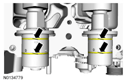
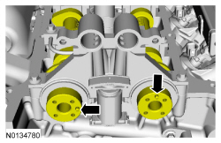
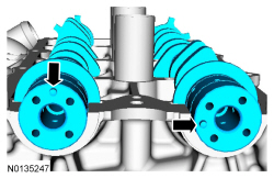
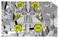
- NOTICE: The camshaft seal gaps must be at the 12 o'clock
position or damage to the engine may occur.
Position the 4 camshaft seals gaps as shown.
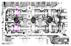
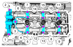
- NOTE: Cylinder head camshaft bearing caps are numbered to verify
that they are assembled in their original positions.
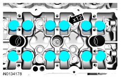
Install the 6 camshaft caps, mega cap, valve train oil tube and the 15 bolts in the sequence shown.
- Tighten to 8 Nm (71 lb-in) then additional 45 degrees.
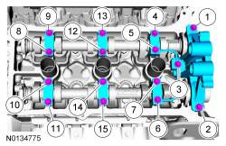
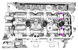
- Loosen the 4 camshaft caps bolts.
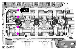
- Tighten the 4 camshaft caps bolts in the sequence shown.
- Tighten bolts 8, 9, 10 and 11 to 8 Nm (71 lb-in) then additional 45 degrees.
- NOTICE: If any components are installed new, the engine valve
clearance must be checked/adjusted or engine damage may occur.
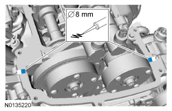
NOTE: Use a camshaft sprocket bolt to turn the camshafts.
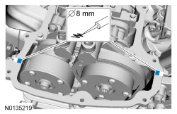
Using a feeler gauge, confirm that the valve tappet clearances are within specification. If valve tappet clearances are not within specification, the clearance must be adjusted by installing new valve tappet(s) of the correct size. For additional information, refer to Valve Clearance Check in this section.
- Remove the 3 bolts and the RH valve train oil tube.
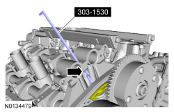
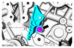
- Rotate the RH camshafts to the TDC position as shown.
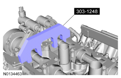
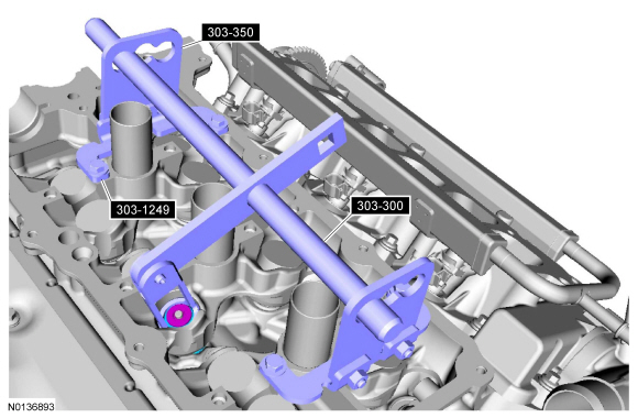
- NOTE: The Camshaft Holding Tool will hold the camshafts in
the TDC position.
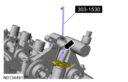
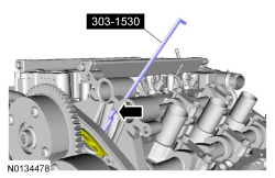
Install the Camshaft Holding Tool onto the flats of the RH camshafts.
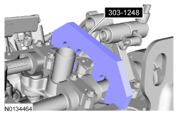
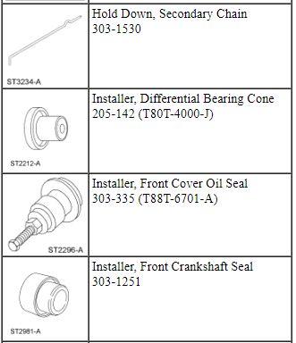
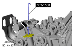
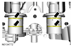
- Compress the RH secondary timing chain tensioner and install the Secondary Chain Hold Down to retain the tensioner in the collapsed position.
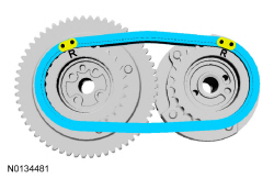
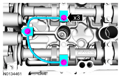
- Assemble the RH VCT assembly, the RH exhaust camshaft sprocket and the
RH secondary timing chain.
- Align the colored links with the timing marks.
- NOTE: It may be necessary to rotate the camshafts slightly, to
install the RH secondary timing assembly.
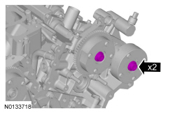
Position the 2 RH VCT assemblies and secondary timing chain onto the camshafts by aligning the holes in the VCT assemblies with the dowel pins in the camshafts.
- Install the 2 new RH VCT bolts and tighten in 4 stages.
- Stage 1: Tighten to 40 Nm (30 lb-ft).
- Stage 2: Loosen one full turn.
- Stage 3: Tighten to 25 Nm (18 lb-ft).
- Stage 4: Tighten an additional 180 degrees.
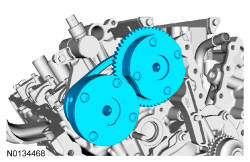
- NOTE: The 2 VCT oil control solenoids are removed for clarity.
Compress the RH secondary timing chain tensioner and remove the Secondary Chain Hold Down.
- Make sure the secondary timing chain is centered on the timing chain tensioner guides.
LH camshafts
- NOTE: Coat the camshafts with clean engine oil prior to
installation.
Position the camshafts onto the LH cylinder head in the neutral position as shown.
- NOTICE: The crankshaft must remain in the freewheeling
position (crankshaft dowel pin at 9 o'clock) until after the camshafts are
installed and the valve clearance is checked/adjusted. Do not turn the
crankshaft until instructed to do so. Failure to follow this process will
result in severe engine damage.
Rotate the crankshaft counterclockwise until the crankshaft dowel pin is in the 9 o'clock position.

- NOTICE: The camshaft seal gaps must be at the 12 o'clock
position or damage to the engine may occur.
Position the 4 camshaft seals gaps as shown.
- NOTE: Cylinder head camshaft bearing caps are numbered to verify
that they are assembled in their original positions.
Install the 6 camshaft caps, mega cap, valve train oil tube and the 15 bolts in the sequence shown.
- Tighten to 8 Nm (71 lb-in) then additional 45 degrees.
- Loosen the 4 camshaft caps bolts.
- Tighten the 4 camshaft caps bolts in the sequence shown.
- Tighten bolts 8, 9, 10 and 11 to 8 Nm (71 lb-in) then additional 45 degrees.
- NOTICE: If any components are installed new, the engine valve
clearance must be checked/adjusted or engine damage may occur.
NOTE: Use a camshaft sprocket bolt to turn the camshafts.
Using a feeler gauge, confirm that the valve tappet clearances are within specification. If valve tappet clearances are not within specification, the clearance must be adjusted by installing new valve tappet(s) of the correct size. For additional information, refer to Valve Clearance Check in this section.

- Remove the 3 bolts and the LH valve train oil tube.

- Rotate the LH camshafts to the TDC position as shown.
- NOTE: The Camshaft Holding Tool will hold the camshafts in the
Top Dead Center (TDC) position.
Install the Camshaft Holding Tool onto the flats of the LH camshafts.

- Compress the LH secondary timing chain tensioner and install the Secondary Chain Hold Down to retain the tensioner in the collapsed position.
- Assemble the 2 LH VCT assemblies and the LH secondary timing chain.
- Align the colored links with the timing marks.
- NOTE: It may be necessary to rotate the camshafts slightly, to
install the LH secondary timing assembly.
Position the 2 LH VCT assemblies and secondary timing chain onto the camshafts by aligning the holes in the VCT assemblies with the dowel pins in the camshafts.
- Install the 2 new LH VCT bolts and tighten in 4 stages.
- Stage 1: Tighten to 40 Nm (30 lb-ft).
- Stage 2: Loosen one full turn.
- Stage 3: Tighten to 25 Nm (18 lb-ft).
- Stage 4: Tighten an additional 180 degrees.
- NOTE: The 2 VCT oil control solenoids are removed for clarity.
Compress the LH secondary timing chain tensioner and remove the Secondary Chain Hold Down.
- Make sure the secondary timing chain is centered on the timing chain tensioner guides.
All camshafts
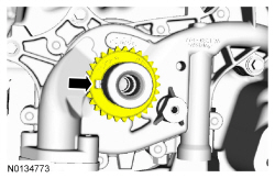
- Rotate the crankshaft clockwise 60 degrees to the TDC position (crankshaft dowel pin at 11 o'clock).
- NOTE: It may be necessary to rotate the camshafts slightly, to
align the timing marks.
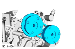
Install the primary timing chain with the colored links aligned with the timing marks on the VCT assemblies and the crankshaft sprocket.
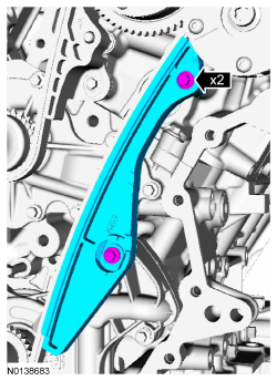
- Install the lower LH primary timing chain guide and the 2 bolts.
- Tighten to 10 Nm (89 lb-in).
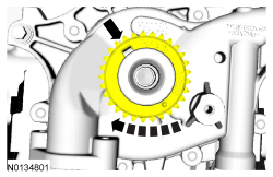
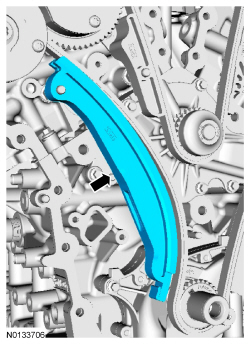
- Install the primary timing chain tensioner arm.
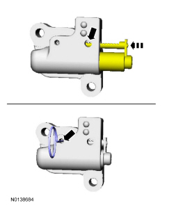
- Reset the primary timing chain tensioner.
- Release the ratchet detent.
- Using a soft-jawed vise, compress the ratchet plunger.
- Align the hole in the ratchet plunger with the hole in the tensioner housing.
- Install a suitable lockpin.
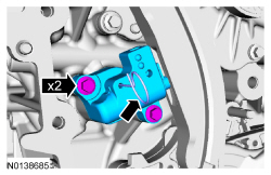
- NOTE: It may be necessary to rotate the camshafts slightly to
remove slack from the timing chain to install the tensioner.
Install the primary tensioner and the 2 bolts.
- Tighten to 10 Nm (89 lb-in).
- Remove the lockpin.
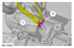
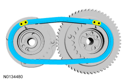
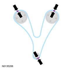
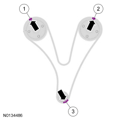
- As a post-check, verify correct alignment of all timing marks.
- There are 48 links in between the RH intake VCT assembly colored link (1) and the LH intake VCT assembly colored link (2).
- There are 35 links in between LH intake VCT assembly colored link (2) and the 2 crankshaft sprocket links (3).
- NOTICE: Do not use excessive force when installing the
Variable Camshaft Timing (VCT) oil control solenoid. Damage to the mega cap
could cause the cylinder head to be inoperable. If difficult to install
the VCT oil control solenoid, inspect the bore and VCT oil control solenoid
to ensure there are no burrs, sharp edges or contaminants present on the
mating surface. Only clean the external surfaces as necessary.
NOTE: A slight twisting motion will aid in the installation of the VCT oil control solenoid.
NOTE: Keep the VCT oil control solenoid clean of dirt and debris.
Install the LH intake VCT oil control solenoid and the bolt.- Tighten to 8 Nm (71 lb-in) then an additional 20 degrees.
- NOTICE: Do not use excessive force when installing the
Variable Camshaft Timing (VCT) oil control solenoid. Damage to the mega cap
could cause the cylinder head to be inoperable. If difficult to install
the VCT oil control solenoid, inspect the bore and VCT oil control solenoid
to ensure there are no burrs, sharp edges or contaminants present on the
mating surface. Only clean the external surfaces as necessary.
NOTE: A slight twisting motion will aid in the installation of the VCT oil control solenoid.
NOTE: Keep the VCT oil control solenoid clean of dirt and debris.
Install the RH intake VCT oil control solenoid and the bolt.- Tighten to 8 Nm (71 lb-in) then an additional 20 degrees.
- Remove the RH Camshaft Holding Tool.

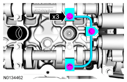
- Install the RH valve train oil tube and the 3 bolts and tighten in 2
stages.
- Stage 1: Tighten to 8 Nm (71 lb-in).
- Stage 2: Tighten an additional 45 degrees.

- Remove the LH Camshaft Holding Tool.
- Install the LH valve train oil tube and the 3 bolts and tighten in 2
stages.
- Stage 1: Tighten to 8 Nm (71 lb-in).
- Stage 2: Tighten an additional 45 degrees.
- NOTICE: Only use a 3M Roloc Bristle Disk (2-in white, part
number 07528) to clean the engine front cover. Do not use metal scrapers,
wire brushes or any other power abrasive disk to clean front cover.
Clean the engine front cover using a 3M Roloc Bristle Disk (2-in white, part number 07528) in a suitable tool turning at the recommended speed of 15,000 rpm.
- Thoroughly wash the engine front cover to remove any foreign material, including any abrasive particles created during the cleaning process.
- NOTICE: Place clean, lint-free shop towels over exposed engine
cavities. Carefully remove the towels so foreign material is not dropped
into the engine. Any foreign material (including any material created while
cleaning gasket surfaces) that enters the oil passages or the oil pan, may
cause engine failure.
NOTICE: Do not use wire brushes, power abrasive discs or 3M Roloc Bristle Disk (2-in white part number 07528) to clean the sealing surfaces of engine block, cylinder heads, and oil pan. These tools can cause contamination that will cause premature engine failure. Remove all traces of the gasket.
Clean the sealing surfaces of the cylinder heads, the cylinder block and the oil pan in the following sequence.- Remove any large deposits of silicone or gasket material.
- Apply silicone gasket remover and allow to set for several minutes.
- Remove the silicone gasket remover. A second application of silicone gasket remover may be required if residual traces of silicone or gasket material remain.
- Apply metal surface prep to remove any remaining traces of oil or coolant and to prepare the surfaces to bond. Do not attempt to make the metal shiny. Some staining of the metal surfaces is normal.
- Make sure the 2 locating dowel pins are seated correctly in the cylinder block.
- Install the Alignment Pins.
- NOTICE: Failure to use Motorcraft High Performance Engine RTV
Silicone may cause the engine oil to foam excessively and result in serious
engine damage.
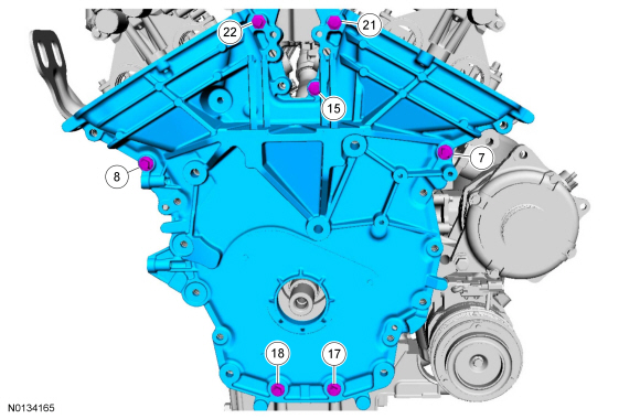
NOTE: The engine front cover and bolts 7, 8, 15, 17, 18, 21 and 22 must be installed within 4 minutes of the initial sealant application. The remainder of the engine front cover bolts must be installed and tightened within 35 minutes of the initial sealant application. If the time limits are exceeded, the sealant must be removed, the sealing area cleaned and sealant reapplied. To clean the sealing area, use silicone gasket remover and metal surface prep. Failure to follow this procedure can cause future oil leakage.
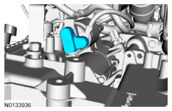
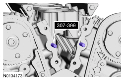
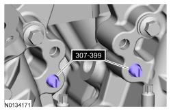
Apply a 3.0 mm (0.11 in) bead of Motorcraft High Performance Engine RTV Silicone to the engine front cover sealing surfaces including the 4 inner bolt bosses.- Apply a 5.5 mm (0.21 in) bead of Motorcraft High Performance Engine RTV Silicone to the oil pan-to-cylinder block joint and the cylinder head-to-cylinder block joint areas of the engine front cover in 5 places as indicated.
- NOTE: Make sure the 2 locating dowel pins are seated correctly in
the cylinder block.
Install the engine front cover and bolts 7, 8, 15, 17, 18, 21 and 22.
- Tighten in sequence to 3 Nm (27 lb-in).
- Remove the Alignment Pins.
- NOTE: Do not tighten the bolt at this time.
Install the M6 engine front cover bolt.
- NOTE: Do not tighten the bolts at this time.
Install the 3 upper M10 engine front cover bolts.
- NOTICE: Do not expose the Motorcraft High Performance Engine
RTV Silicone to engine oil for at least 90 minutes after installing the
engine front cover. Failure to follow this instruction may cause oil
leakage.
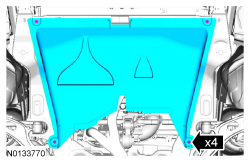
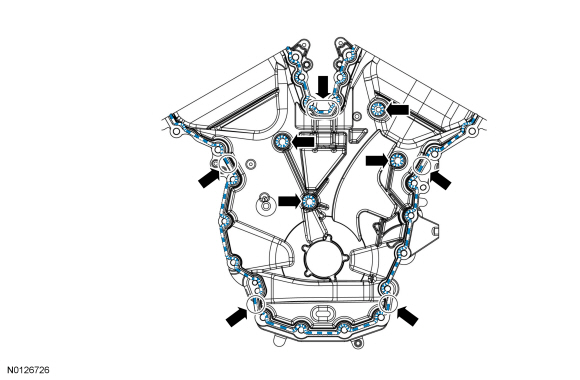
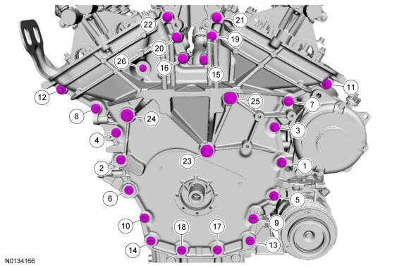
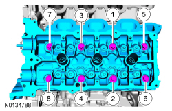
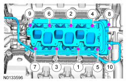
Install the remaining engine front cover bolts. Tighten all of the engine front cover bolts in the sequence shown in 7 stages:
- Stage 1: Tighten bolts 1 thru 22 to 10 Nm (89 lb-in).
- Stage 2: Tighten bolts 23, 24 and 25 to 15 Nm (133 lb-in).
- Stage 3: Tighten bolt 26 to 10 Nm (89 lb-in).
- Stage 4: Loosen bolt 26 one full turn.
- Stage 5: Tighten bolts 23, 24 and 25 to 30 Nm (22 lb-ft) plus an additional 90 degrees.
- Stage 6: Tighten bolts 1 thru 22 to 20 Nm (177 lb-in) plus an additional 45 degrees.
- Stage 7: Tighten bolt 26 to 10 Nm (89 lb-in) plus an additional 45 degrees.
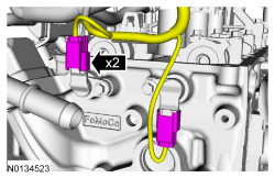
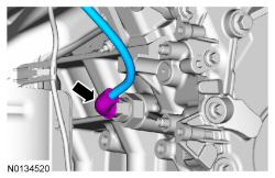
- Install the fuel supply tube-to-engine front cover bolt.
- Tighten to 10 Nm (89 lb-in).
- Position the generator and install the stud and nut.
- Tighten the stud to 8 Nm (71 lb-in).
- Tighten the nut to 47 Nm (35 lb-ft).
- Tighten the bolt to 47 Nm (35 lb-ft).
- NOTE: Installation of new seals is only required if damaged seals
were removed.
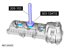
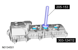
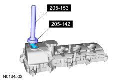
Using the VCT Spark Plug Tube Seal Installer and Handle, install new spark plug tube seals.
- NOTE: Installation of new seals is only required if damaged seals
were removed.
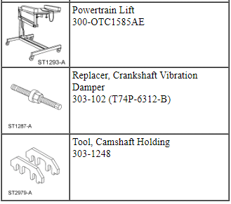
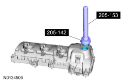
Using the Differential Bearing Cone Installer and Handle, install new VCT solenoid seal(s).
- NOTICE: Failure to use the correct Motorcraft High
Performance Engine RTV Silicone may cause the engine oil to foam excessively
and result in serious engine damage.
NOTE: If the valve cover is not installed and the fasteners tightened within 4 minutes, the sealant must be removed and the sealing area cleaned. To clean the sealing area, use silicone gasket remover and metal surface prep. Failure to follow this procedure can cause future oil leakage.
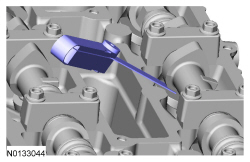
Apply an 8 mm (0.31 in) bead of Motorcraft High Performance Engine RTV Silicone to the engine front cover-to-RH cylinder head joints.
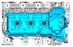
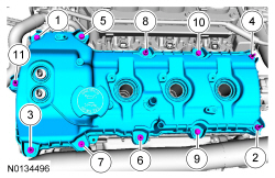
- Using a new gasket, install the RH valve cover and tighten the 4 bolts
and 7 stud bolts.
- Tighten in the sequence shown to 10 Nm (89 lb-in).
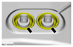
- Make sure the VCT seals in the valve cover are below the top of the VCT oil control solenoid electrical connector or the VCT seal may leak oil.
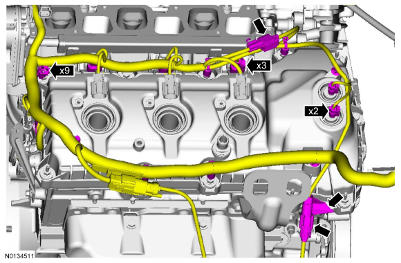
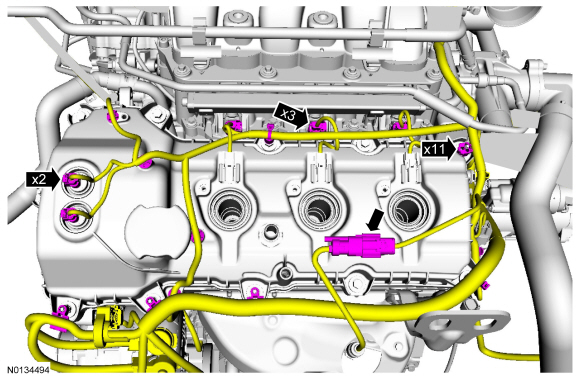
- Install the engine wiring harness to the RH valve cover.
- Position the wiring harness and attach the 9 wiring harness retainers to the RH valve cover and stud bolts.
- Connect the CHT sensor wiring harness jumper electrical connector.
- Connect the 3 fuel injector electrical connectors.
- Connect and attach the RH CMS electrical connector.
- Connect the 2 VCT oil control solenoid electrical connectors.
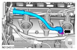
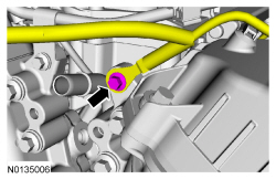
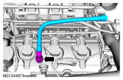
- Install the PCV crankcase vent tube.
- NOTE: Apply a small amount of dielectric grease to the inside of
the ignition coil-on-plug boots before attaching to the spark plugs.
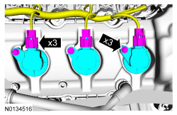
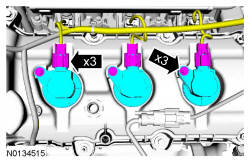
Install the 3 RH coil-on-plugs and the 3 bolts.
- Tighten to 7 Nm (62 lb-in).
- Connect the 3 coil-on-plug electrical connectors.
- Using a new gasket, install the intake manifold and the 7 bolts.
- Tighten in the sequence shown in 2 stages.
- Stage 1: Tighten to 10 Nm (89 lb-in).
- Stage 2: Tighten an additional 45 degrees.
- Tighten in the sequence shown in 2 stages.
- Install the upper intake manifold support bracket bolt.
- Tighten to 10 Nm (89 lb-in).
- Attach the 2 coolant tube retainers to the upper intake manifold.
- Connect the crankcase ventilation hose to the upper intake manifold.
- Connect the EVAP vapor tube to the EVAP canister vent solenoid. For
additional information, refer to Section 310-00.
- Attach the EVAP vapor tube to the 2 retainers.
- Connect the EVAP canister vent solenoid and throttle body electrical
connectors.
- Attach the wiring harness pin-type retainer to the upper intake manifold.
- NOTE: Installation of new seals is only required if damaged seals
were removed.
Using the VCT Spark Plug Tube Seal Installer and Handle, install new spark plug tube seals.
- NOTE: Installation of new seals is only required if damaged seals
were removed.
Using the Differential Bearing Cone Installer and Handle, install new VCT solenoid seal(s).
- NOTICE: Failure to use Motorcraft High Performance Engine RTV
Silicone may cause the engine oil to foam excessively and result in serious
engine damage.
NOTE: If the valve cover is not installed and the fasteners tightened within 4 minutes, the sealant must be removed and the sealing area cleaned. To clean the sealing area, use silicone gasket remover and metal surface prep. Failure to follow this procedure can cause future oil leakage.
Apply an 8 mm (0.31 in) bead of Motorcraft High Performance Engine RTV Silicone to the engine front cover-to-LH cylinder head joints.
- Using a new gasket, install the LH valve cover and tighten the 4 bolts
and 7 stud bolts.
- Tighten in the sequence shown to 10 Nm (89 lb-in).
- Make sure the VCT seals in the valve cover are below the top of the VCT oil control solenoid electrical connector or the VCT seal may leak oil.

- Install the engine wiring harness to the LH valve cover.
- Position the wiring harness and attach the 11 wiring harness retainers to the LH valve cover and stud bolts.
- Connect the 3 fuel injector electrical connectors.
- Connect and attach the LH HO2S electrical connector.
- Connect the 2 VCT oil control solenoid electrical connectors.
- Install the ground wire bolt to the engine front cover.
- Tighten to 10 Nm (89 lb-in).
- NOTE: Apply a small amount of dielectric grease to the inside of
the ignition coil-on-plug boots before attaching to the spark plugs.
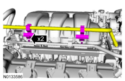
Install the 3 LH -coil-on-plugs and the 3 bolts.
- Tighten to 7 Nm (62 lb-in.
- Connect the 3 coil-on-plug electrical connectors.
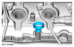
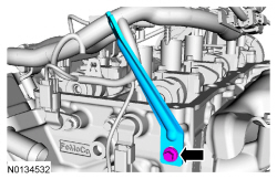
- Install the oil level indicator.
- Install the crankcase vent tube. For additional information, refer to the quick connect coupling procedure in Section 310-00.
- Install the accessory drive belt tensioner and the 3 bolts.
- Tighten to 11 Nm (97 lb-in).
- NOTE: Apply clean engine oil to the crankshaft front seal bore in
the engine front cover.
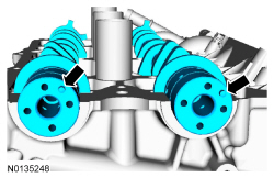
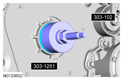
Using the Crankshaft Vibration Damper Replacer and Front Crankshaft Seal Installer, install a new crankshaft front seal.
- NOTE: Lubricate the outside diameter sealing surfaces with clean
engine oil.
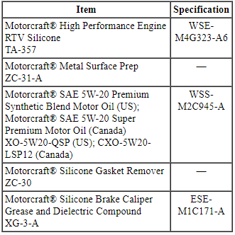
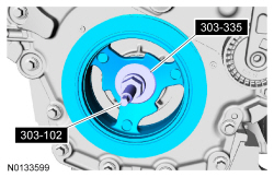
Using the Crankshaft Vibration Damper Replacer and Front Cover Oil Seal Installer, install the crankshaft pulley.
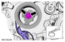
- Using the strap wrench, install the crankshaft pulley washer and new
bolt and tighten in 4 stages.
- Stage 1: Tighten to 120 Nm (89 lb-ft).
- Stage 2: Loosen one full turn.
- Stage 3: Tighten to 50 Nm (37 lb-ft).
- Stage 4: Tighten an additional 90 degrees.
- Raise the subframe and powertrain assembly into the vehicle.
- Install the engine mount and the 3 bolts.
- Tighten to 90 Nm (66 lb-ft).
- Install the 4 engine mount nuts.
- Tighten to 63 Nm (46 lb-ft).

- Install the transaxle support insulator bracket, the 3 nuts and the
bolt.
- Tighten the bolt to 80 Nm (59 lb-ft).
- Tighten the 3 nuts to 63 Nm (46 lb-ft).

- Install the transaxle support insulator through bolt and nut.
- Tighten to 175 Nm (129 lb-ft).
- NOTE: RH shown, LH similar.
Align the subframe and install the new front subframe bolts.
- Tighten to 200 Nm (148 lb-ft).
- NOTE: RH shown, LH similar.
Install the rear subframe brackets and the new subframe bracket-to-body bolts.
- Finger tight at this stage.
- NOTE: RH shown, LH similar.
Install the new subframe bracket bolts.
- Tighten to 150 Nm (111 lb-ft).

- NOTE: RH shown, LH similar.
Tighten the subframe bracket-to-body bolts to 55 Nm (41 lb-ft).
- Remove the ratchet strap from the front of the subframe to the rear of the subframe.
- Remove the Adjustable Grip Arm and the powertrain lift table.

- NOTE: LH shown, RH similar.
Install the strut to the wheel knuckle and install the strut-to-wheel knuckle nuts and bolts.
- Tighten to 250 Nm (184 lb-ft).
- NOTE: LH shown, RH similar.
Install the brake caliper and the guide pin bolts.
- 432 mm (17 in) brakes: Tighten to 72 Nm (53 lb-ft).
- 457 mm (18 in) brakes: Tighten to 75 Nm (55 lb-ft).
- NOTICE: Do not tighten the wheel hub nut with the vehicle on
the ground. The nut must be tightened to specification before the vehicle is
lowered onto the wheels. Wheel bearing damage will occur if the wheel
bearing is loaded with the weight of the vehicle applied.
NOTE: LH shown, RH similar.
NOTE: Apply the brake to keep the halfshaft from rotating.
Using the previously removed wheel hub nut, seat the LH and RH halfshafts.- Tighten to 350 Nm (258 lb-ft).
- Remove and discard the wheel hub nuts.

- NOTICE: The wheel hub nut contains a one time locking chemical
that is activated by the heat created when it is tightened. Install and
tighten the new wheel hub nut to specification within 5 minutes of starting
it on the threads. Always install a new wheel hub nut after loosening or
when not tightened within the specified time or damage to the components can
occur.
NOTE: LH shown, RH similar.
NOTE: Apply the brake to keep the halfshaft from rotating.
Install a new wheel hub nuts.- Tighten to 350 Nm (258 lb-ft).

- NOTE: LH shown, RH similar.
Install the new upper stabilizer link nut.
- Tighten to 150 Nm (111 lb-ft).

- NOTE: LH shown, RH similar.
Install the wheel speed sensor and the bolt.
- Tighten to 15 Nm (133 lb-in).
- Connect the transaxle cooler tubes and install the 2 secondary latches.
- If equipped, install the oil cooler hose retainer to the subframe.
- If equipped, connect the 2 oil cooler coolant hoses.

- NOTE: Do not lubricate the engine oil filter gasket with oil.
Install a new engine oil filter.
- Tighten to 5 Nm (44 lb-in) and then rotate an additional 180 degrees.
All-Wheel Drive (AWD) vehicles
- Line up the index marks on the rear driveshaft to the index marks on
the PTU flange made during removal and install the 4 bolts.
- Tighten to 70 Nm (52 lb-ft).

All vehicles
- Install the exhaust Y-pipe. For additional information, refer to Section 309-00.
- NOTICE: Do not allow the intermediate shaft to
rotate while it is disconnected from the gear or damage to the clockspring
may occur. If there is evidence that the intermediate shaft has rotated, the
clockspring must be removed and recentered. For additional information,
refer to Section 501-20B.
Align and connect the steering column shaft to the steering gear and install the bolt.
- Tighten to 20 Nm (177 lb-in).
- If equipped, attach the engine block heater harness to the radiator support.
- Connect the transaxle control cable to the shift cable bracket.
- Connect the transaxle control cable to the control lever.

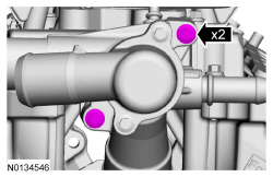
- Connect the upper radiator hose, lower radiator hose and 2 heater hoses to the thermostat housing.

- Install the ground wire to the RH shock tower and install the bolt.
- Tighten to 10 Nm (89 lb-in).

- Install the engine wiring harness retainer to the bulkhead.
- Slide the wiring harness in the bulkhead.
- Make sure the wiring harness retainer tab is below the bulkhead lip.
- Connect the engine harness electrical connector.
- Attach the wiring harness retainer.
- Connect the 2 PCM electrical connectors.
- Connect the Evaporative Emission (EVAP) tube and the fuel supply tube quick connect coupling. For additional information, refer to Section 310-00.
- Connect the brake booster vacuum hose to the upper intake manifold.
- Connect the degas bottle coolant hose to the engine coolant tube.

- Install the degas bottle. For additional information, refer to Section 303-03.
- Using a new O-ring seal and gasket seal, connect the upper A/C tube to
the condenser and install the nut.
- Tighten to 15 Nm (133 lb-in).
- Connect the A/C pressure switch electrical connector.

- Using a new O-ring seal and gasket seal, connect the A/C tube and
install the nut.
- Tighten to 15 Nm (133 lb-in).

- Install the accessory drive belt. For additional information, refer to Section 303-05.
- Position the splash shield and install the 3 pin-type retainers.

- Install the front wheels and tires. For additional information, refer to Section 204-04.
- If equipped, install the skid plate and the 10 retainers.
- Tighten to 70 Nm (52 lb-ft).

- If equipped, install the underbody shield and attach the 4 retainers.

- Connect the engine wiring harness electrical connector.

- Install the ground wire cable and the retainer.
- Tighten to 10 Nm (89 lb-in).
- Connect the 2 battery feed cables to the positive battery terminal and
install the nut.
- Tighten to 5 Nm (44 lb-in).
- Install the battery tray. For additional information, refer to Section 414-01.
- Install the engine Air Cleaner (ACL) and ACL outlet pipe. For additional information, refer to Section 303-12.
- Install the strut tower brace and the 4 nuts.
- Tighten to 35 Nm (26 lb-ft).

- Install the cowl panel grille. For additional information, refer to Section 501-02.
- Fill the engine with clean engine oil.
- Fill and bleed the cooling system. For additional information, refer to Section 303-03.
- Recharge the A/C system. For additional information, refer to Section 412-00.
- Perform the Misfire Monitor Neutral Profile Correction procedure, following the on-screen instructions.
Valve Tappets
Material
NOTICE: During engine repair procedures, cleanliness is extremely important. Any foreign material, including any material created while cleaning gasket surfaces that enters the oil passages, coolant passages or the oil pan, may cause engine failure.
- NOTE: The valve tappets must be installed in their original
positions.
NOTE: Coat the valve tappets with clean engine oil prior to installation.
Install the valve tappets.

- Depending on the valve tappets being serviced, install the LH and/or the RH camshafts. For additional information, refer to Camshaft in this section.
Valve Spring, Retainer and Seal
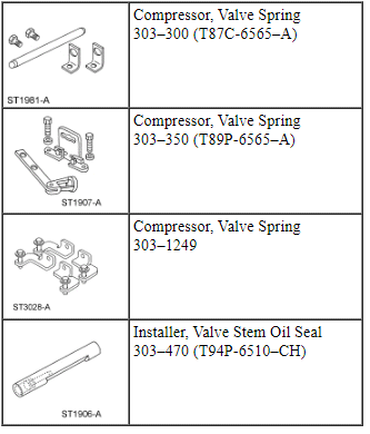
Special Tool(s)
Material
- NOTE: Apply the specified lubricant to the specified component.
Using the Valve Stem Oil Seal Installer, install a new valve stem seal.
- Using the Valve Spring Compressors, install the valve spring, retainer and key.
- Install the valve tappets. For additional information, refer to Valve Tappets in this section.
Cylinder Head - RH
Material
NOTE: If the cylinder head is replaced, a new secondary timing chain tensioner will need to be installed.
NOTE: The valve tappets must be installed in their original positions. Coat the valve tappets with clean engine oil prior to installation.
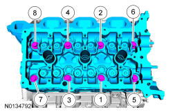
- Install a new gasket, the RH cylinder head and 8 new bolts. Tighten in
the sequence shown in 5 stages:
- Stage 1: Tighten to 20 Nm (177 lb-in).
- Stage 2: Tighten to 35 Nm (26 lb-ft).
- Stage 3: Tighten 90 degrees.
- Stage 4: Tighten 90 degrees
- Stage 5: Tighten 45 degrees.
- Install the M6 bolt.
- Tighten to 10 Nm (89 lb-in).
- NOTE: The valve tappets must be installed in their original
positions.
NOTE: Coat the valve tappets with clean engine oil prior to installation.
Install the valve tappets.

- Install and connect the CHT sensor jumper harness.
- NOTICE: If the engine is repaired or replaced because of upper
engine failure, typically including valve or piston damage, check the intake
manifold for metal debris. If metal debris is found, install a new intake
manifold. Failure to follow these instructions can result in engine damage.
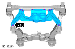
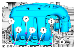
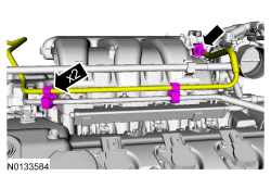
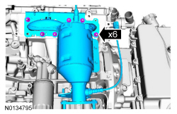
Using new intake manifold and thermostat housing gaskets, install the lower intake manifold and the 10 bolts.
- Tighten in the sequence shown to 10 Nm (89 lb-in).

- Install the 2 thermostat housing-to-lower intake manifold bolts.
- Tighten to 10 Nm (89 lb-in).

- NOTE: Align the bracket with the index mark made during removal.
Install the upper intake manifold bracket and the bolt.
- Tighten to 10 Nm (89 lb-in).
- Install the engine lifting eye and the 2 bolts.
- Tighten to 24 Nm (18 lb-ft).
- Install the RH primary timing chain guide and the bolt.
- Tighten to 10 Nm (89 lb-in).
- Install the RH cylinder block drain plug or if equipped, the block
heater.
- Tighten the cylinder block drain plug to 10 Nm (89 lb-in) plus an additional 720 degrees.
- Tighten the block heater to 40 Nm (30 lb-ft).

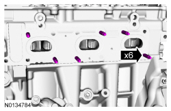
- Install 6 new RH exhaust manifold studs.
- Tighten to 12 Nm (106 lb-in).

- NOTICE: Failure to tighten the exhaust manifold nuts to
specification a second time will cause the exhaust manifold to develop an
exhaust leak.
Using a new gasket, install the RH exhaust manifold and 6 new nuts. Tighten in 2 stages in the sequence shown:
- Stage 1: Tighten to 20 Nm (177 lb-in).
- Stage 2: Tighten to 25 Nm (18 lb-ft).
- Install the RH catalytic converter heat shield and the 4 bolts.
- Tighten to 10 Nm (89 lb-in).

- Install the LH cylinder block drain plug.
- Tighten to 16 Nm (142 lb-in) plus an additional 180 degrees.

- Install the ground wire and the bolt on the RH cylinder.
- Tighten to 10 Nm (89 lb-in).
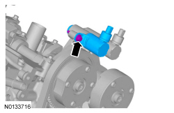
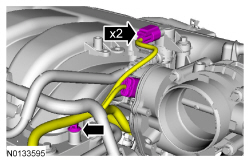
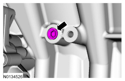
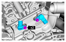
- Install the 2 CMP sensors and the 2 bolts.
- Tighten to 10 Nm (89 lb-in).
- Connect the 2 RH Camshaft Position Camshaft Position (CMP) sensor electrical connectors.
- If equipped, disconnect the block heater electrical connector.
- Install the block heater wiring harness to the engine.
- If equipped, install the block heater heat shield.

- Install the RH camshafts. For additional information, refer to Camshaft in this section.
Cylinder Head - LH
Material
NOTICE: During engine repair procedures, cleanliness is extremely important. Any foreign material, including any material created while cleaning gasket surfaces that enters the oil passages, coolant passages or the oil pan, can cause engine failure.
NOTE: If the cylinder head is replaced, a new secondary timing chain tensioner will need to be installed.
NOTE: The valve tappets must be installed in their original positions. Coat the valve tappets with clean engine oil prior to installation.
- NOTE: If the cylinder head is replaced, a new secondary timing
chain tensioner will need to be installed.
Install a new gasket, the LH cylinder head and 8 new bolts. Tighten in the sequence shown in 5 stages:
- Stage 1: Tighten to 20 Nm (177 lb-in).
- Stage 2: Tighten to 35 Nm (26 lb-ft).
- Stage 3: Tighten 90 degrees.
- Stage 4: Tighten 90 degrees
- Stage 5: Tighten 45 degrees.
- Install the M6 bolt.
- Tighten to 10 Nm (89 lb-in).
- NOTE: The valve tappets must be installed in their original
positions.
NOTE: Coat the valve tappets with clean engine oil prior to installation.
Install the valve tappets.
- Install the LH upper primary timing chain guide and the bolt.
- Tighten to 10 Nm (89 lb-in).
- NOTICE: If the engine is repaired or replaced because of upper
engine failure, typically including valve or piston damage, check the intake
manifold for metal debris. If metal debris is found, install a new intake
manifold. Failure to follow these instructions can result in engine damage.
Using new intake manifold and thermostat housing gaskets, install the lower intake manifold and the 10 bolts.
- Tighten in the sequence shown to 10 Nm (89 lb-in).
- Install the 2 thermostat housing-to-lower intake manifold bolts.
- Tighten to 10 Nm (89 lb-in).
- Install the RH cylinder block drain plug or, if equipped, the block
heater.
- Tighten the cylinder block drain plug to 10 Nm (89 lb-in) plus an additional 720 degrees.
- Tighten the block heater to 40 Nm (30 lb-ft).
- Install the LH cylinder block drain plug.
- Tighten to 16 Nm (142 lb-in) plus an additional 180 degrees.
- Install 6 new LH exhaust manifold studs.
- Tighten to 12 Nm (106 lb-in).
- Using a new gasket, install the LH catalytic converter manifold and 3
new lower LH catalytic converter manifold-to-cylinder head nuts.
- Install the 3 new upper LH catalytic converter manifold-to-cylinder head nuts and tighten to 25 Nm (18 lb-ft).
- Tighten the 3 lower LH catalytic converter manifold-to-cylinder head nuts to 25 Nm (18 lb-ft).
- Install the LH exhaust heat shield and the 3 bolts.
- Tighten to 10 Nm (89 lb-in).
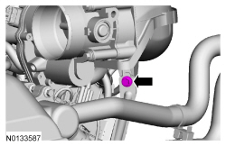
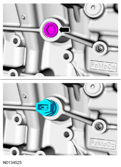
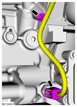
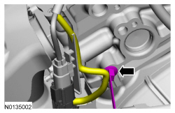
- Connect the Engine Oil Pressure (EOP) switch electrical connector and the wiring harness pin-type retainer.
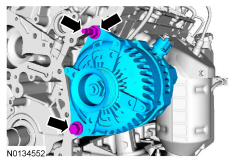
- Install the generator stud, generator and the nut and bolt.
- Tighten the stud to 8 Nm (71 lb-in).
- Tighten the nut and bolt to 47 Nm (35 lb-ft).
- Connect the generator B+ cable and install the nut.
- Tighten to 17 Nm (150 lb-in).

- Position back the generator B+ cable cover and connect the generator electrical connector.
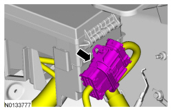
- Install the A/C compressor, the 2 stud bolts and the nut.
- Tighten to 25 Nm (18 lb-ft).
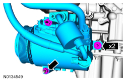
- Connect the 2 A/C compressor electrical connectors.
- Attach the A/C wiring harness retainer.

- Install the wiring harness retainer to the rear of the LH cylinder head.
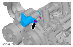
- NOTE: Lubricate the 2 CMP sensor O-ring seals with clean engine
oil.
Install the 2 LH CMP sensors and the 2 bolts.
- Tighten to 10 Nm (89 lb-in).
- Connect the 2 LH CMP sensors electrical connectors.
- If equipped, connect the block heater electrical connector.
- Install the block heater wiring harness to the engine.

- If equipped, install the block heater heat shield.
- Install the LH camshafts. For additional information, refer to Camshaft in this section.
 Assembly
Engine
Special Tool(s)
Material
Engine Upper
Engine Front
Engine Upper - LH Cylinder Head
Engine Upper - RH Cylinder Head
Timing Drive Components
Lower Engine Block (View 1)
Lowe ...

Other materials:
Hydraulic Brake Actuation
SPECIFICATIONS
Material
Torque Specifications
DESCRIPTION AND OPERATION
Adjustable Pedals
Overview
The adjustable pedal feature uses an electrical motor to adjust the brake and
accelerator pedal positions forward and rearward to increase driver comfort. Two
adjustable pedal systems are available ...
Jacking and Lifting
WARNING: When jacking or lifting the vehicle, block all wheels remaining
on the ground. Set the parking brake if the rear wheels will remain on the
ground. These actions help prevent unintended vehicle movement. Failure to
follow these instructions may result in serious personal injury.
&nb ...
Headlamp exit delay
You can set the delay time to keep the headlamps on for up to three
minutes after the ignition is turned off.
Follow the steps below to change the delay time (Steps 1 through 6
must be done within 10 seconds):
1. Turn the ignition off.
2. Turn the lighting control to the autolamp position.
...
