SPECIFICATIONS
Torque Specifications
a Refer to the procedure in this section.
DESCRIPTION AND OPERATION
Turbocharger
Component Location
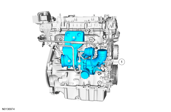
Overview
NOTICE: Whenever turbocharger air intake system components are removed, always cover open ports to protect from debris. It is important that no foreign material enter the system. The turbocharger compressor vanes are susceptible to damage from even small particles. All components should be inspected and cleaned, if necessary, prior to installation or reassembly.
The turbocharger is an exhaust-driven centrifugal air compressor. Its purpose is to increase power output by supplying compressed air to the engine. The internal components are cooled by engine oil, engine coolant and air. Engine oil and coolant are circulated through the center housing which acts as a heat barrier between the "hot" turbine and the "cold" compressor. Bearings are sleeve type and lubricated by engine oil. Oil is circulated to the turbocharger center housing and returned to the sump through an oil drain in the center housing.
Expanding exhaust gases drive the turbine shaft assembly to speeds up to 200,000 rpm. Filtered air entering the compressor side of the turbocharger is compressed and delivered through a Charge Air Cooler (CAC). The very hot compressed air is cooled, then continues on to fill the intake manifold at a higher pressure than atmospheric pressure. Because considerably more air is forced into the intake manifold, the results are increased power, fuel efficiency and the ability to maintain power at higher altitudes.
The turbocharger wastegate is designed to be in the closed position. The wastegate is normally closed at the onset of engine run. The wastegate is pressure actuated.
The EcoBoost turbocharger is connected to the cylinder head. This configuration improves engine responsiveness due to the reduced inertia of a small turbocharger. This also leads to an improved turbocharger package and better utilization of heat energy from the compact cylinder head to turbocharger flange. The compact design of the system allows the catalysts to be located very close to the turbocharger outlet for improved emissions.
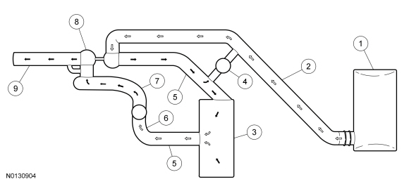
System Operation
System Diagram
NOTE: Black arrows indicate hot, white arrows indicate cold.
DIAGNOSIS AND TESTING
Turbocharger
Principles of Operation
The turbocharger is an exhaust-driven centrifugal air compressor. Its purpose is to increase power output by supplying compressed air to the engine. The internal components are oil, coolant and air cooled. Engine oil and coolant are circulated through the center housing which acts as a heat barrier between the "hot" turbine and the "cold" compressor. Bearings are sleeve type and lubricated by engine oil. Oil is circulated to the turbocharger center housing and returned to the sump through an oil drain in the center housing.
Expanding exhaust gases drive the turbine shaft assembly to speeds up to 200,000 rpm. Filtered air entering the compressor side of the turbocharger is compressed and delivered through a Charge Air Cooler (CAC). The very hot compressed air is cooled, then continues on to fill the intake manifold at a higher pressure than atmospheric pressure. Because considerably more air is forced into the intake manifold, the results are increased power, fuel efficiency and the ability to maintain power at higher altitudes.
Inspection and Verification
NOTE: This section provides mechanical diagnosis of the turbocharger assembly. If there is a Malfunction Indicator Lamp (MIL) illuminated, or DTCs are present, these should be diagnosed prior to performing turbocharger mechanical diagnosis. Refer to the Powertrain Control/Emissions Diagnosis (PC/ED) manual.
- Verify the customer concern.
- Inspect the entire turbocharger system for obvious signs of damage or
other mechanical concerns, using the following chart.
Visual Inspection Chart
Mechanical
- Oil inlet pipe and connection
- Oil outlet pipe and connection
- Compressor housing inlet circuit and piping
- Compressor housing outlet circuit and piping
- Turbine housing inlet circuit and piping
- Turbine housing outlet circuit and piping
- Turbocharger actuator tubing or linkage
- If the concern(s) remains after the inspection, GO to Symptom Chart.
- If a driveability condition still exists, refer to the Powertrain Control/Emissions Diagnosis (PC/ED) manual.
Symptom Chart
Component Tests
Turbocharger Internal Oil Leak Test
NOTE: Some engine oil may be present in the turbocharger compressor inlet and in the air inlet components due to the crankcase breather system.
Check the turbocharger compressor inlet for evidence of oil. If excessive oil is present, this indicates that the failure could be in the engine or turbocharger. Refer to Section 303-00 or the following turbocharger check. If excessive oil is found in the turbocharger compressor outlet, check the Charge Air Cooler (CAC) for oil contamination. If contamination is present, flush the CAC. Refer to Section 303-12.
Check the turbocharger turbine outlet for evidence of oil. If excess liquid oil is present in the outlet, remove the turbocharger from the engine and examine the oil supply and return passages in the turbocharger, engine block and the turbocharger oil drain tube for restriction. If no restriction is found, install a new turbocharger.
Check for Free Rotation - Off Vehicle
NOTE: The turbocharger must be pre-oiled before carrying out this check.
NOTE: Turbine and compressor wheels must spin freely when turned by hand. No housing contact is permitted.
Inspect the turbocharger compressor and turbine fins for damage. If the compressor or turbine wheel fins are damaged, replace the turbocharger.
Press and rotate the turbocharger shaft, then repeat from the opposite side. If either the compressor wheel or the turbine wheel contacts the housing, the bearings are bad and a new turbocharger must be installed.
REMOVAL AND INSTALLATION
Turbocharger
Removal
NOTICE: Whenever turbocharger air intake system components are removed, always cover open ports to protect from debris. It is important that no foreign material enter the system. The turbocharger compressor vanes are susceptible to damage from even small particles. All components should be inspected and cleaned, if necessary, prior to installation or reassembly.
NOTICE: The turbocharger wastegate actuator locknuts are not adjustable. Do not attempt to adjust the wastegate actuator locknuts or engine damage may occur.
NOTICE: Do not disassemble the turbocharger. Doing so may cause turbocharger or engine damage to occur.
NOTE: Removal steps in this procedure may contain installation details.
- With the vehicle in NEUTRAL, position it on a hoist. For additional information, refer to Section 100-02.
-
-
- Tighten to 5 Nm (44 lb-in).
-
-
- Tighten to 5 Nm (44 lb-in).
- Remove the catalytic converter. For additional information, refer to Section 309-00.
-
- Tighten to 5 Nm (44 lb-in).
-
- Tighten to 5 Nm (44 lb-in).
- Drain the cooling system. For additional information, refer to Section 303-03.
- NOTE: Make sure that 2 new linked washers are installed.
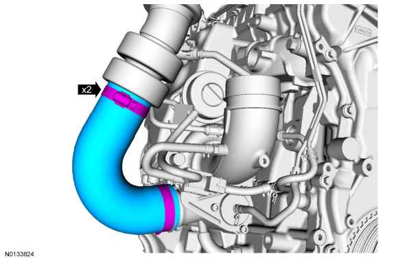
NOTE: Both water outlet tube clamps must be installed between the 2 paint stripes on hoses.
Discard the specified component. Follow local disposal regulations.- Tighten to 28 Nm (21 lb-ft).
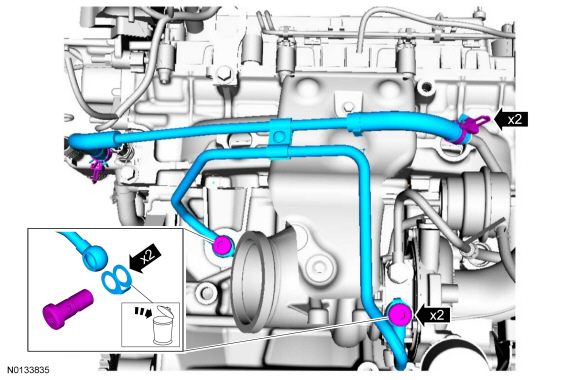
- NOTE: Make sure that a new turbocharger oil supply pipe and 4 new
gaskets are installed.
Discard the specified component. Follow local disposal regulations.
- Tighten to 25 Nm (18 lb-ft).
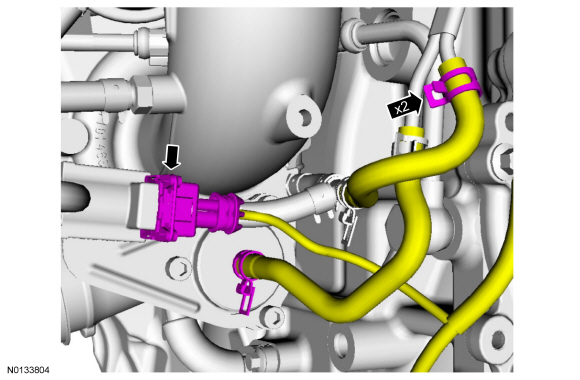
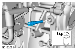
- NOTE: Make sure that a new turbocharger oil supply filter is
installed.
Discard the specified component. Follow local disposal regulations.
-
- Tighten to 10 Nm (89 lb-in).
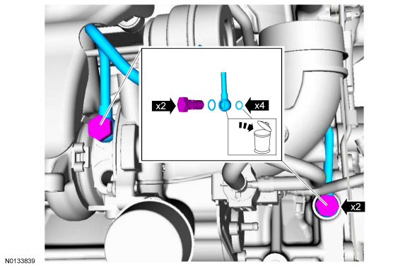
- NOTE: Make sure that a new turbocharger oil drain tube is
installed. By not doing so, the turbocharger oil drain tube may leak and
cause engine damage.
Discard the specified component. Follow local disposal regulations.
- Tighten to 10 Nm (89 lb-in).
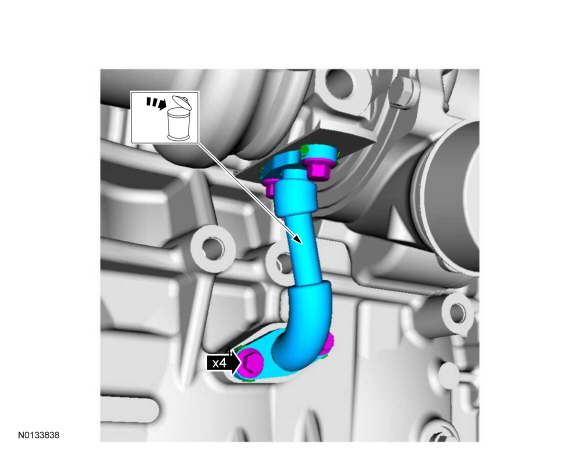
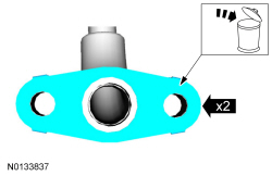
- NOTE: Make sure that 2 new turbocharger oil drain tube gaskets
are installed. By not doing so, the turbocharger oil drain tube may leak and
cause engine damage.
Discard the 2 turbocharger oil return tube gaskets. Discard the specified component. Follow local disposal regulations.
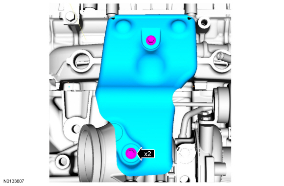
- NOTE: Make sure that 4 new turbocharger nuts are installed.
Discard the specified component. Follow local disposal regulations.
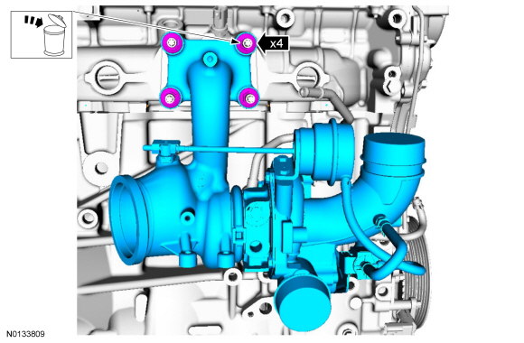
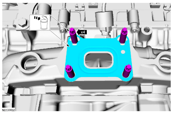
- NOTE: Make sure that a new turbocharger gasket and 4 new
turbocharger-to-cylinder head studs are installed.
Remove and discard the turbocharger gasket and the 4 turbocharger-to-cylinder head studs. Discard the specified component. Follow local disposal regulations.
- Tighten to 17 Nm (150 lb-in).
Installation
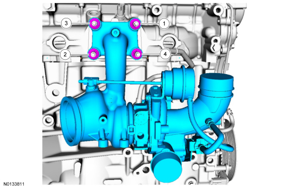
- NOTE: Make sure that 4 new turbocharger-to-cylinder head studs, 4
new turbocharger nuts and a new turbocharger gasket are installed.
Tighten in the sequence shown to 50 Nm (37 lb-ft).
- To install, reverse the removal procedure.
 Fuel Charging and Controls - Turbocharger, 3.5L GTDI
SPECIFICATIONS
Material
Torque Specifications
a Refer to the procedure in this section.
DESCRIPTION AND OPERATION
Turbocharger
NOTICE: Whenever turbocharger air intake system components ar ...
 Fuel Charging and Controls - 3.7L Ti-VCT
SPECIFICATIONS
Material
Torque Specifications
DESCRIPTION AND OPERATION
Fuel Charging and Controls
Component Locations
WARNING: Do
not smoke, carry lighted tobacco or have an open flame of any type ...
Other materials:
Removal
Engine
Special Tool(s)
WARNING: Do not smoke, carry lighted tobacco or have an open flame of any
type when working on or near any fuel-related component. Highly flammable
mixtures are always present and may be ignited. Failure to follow these
instructions may result in serious personal inj ...
Diagnosis and Testing
External Controls
Inspection and Verification
Verify the customer concern by operating the system.
Visually inspect for obvious signs of mechanical or electrical damage.
If the concern is not visually evident, verify the symptom. GO
to Symptom Chart.
Visual Inspection Chart
DTC Char ...
Front Suspension
SPECIFICATIONS
Material
Torque Specifications
a Refer to the procedure in this section.
DESCRIPTION AND OPERATION
Front Suspension
The front suspension consists of the following components:
Wheel bearing and wheel hubs
Wheel studs
Lower arms
Stabilizer bar
Stabilizer bar links
Struts
...
