Uni-Body, Subframe and Mounting System
SPECIFICATIONS
Torque Specifications
DESCRIPTION AND OPERATION
Subframe and Mounting Systems
The front subframe is bolted to the body and:
- aids in structural support.
- provides the mounting surface for the steering gear, the front suspension lower arms, engine roll restrictor and the stabilizer bar.
- front subframe bushings are serviceable.
The rear subframe is bolted to the body and:
- aids in structural support.
- provides the mounting surface for the rear suspension upper control arms, rear suspension lower control arms and (if equipped) a mounting location for the rear differential.
For body dimension specifications, refer to Section 501-35.
REMOVAL AND INSTALLATION
Special Tool(s)
Material
Removal
NOTICE: Suspension fasteners are critical parts because they affect performance of vital components and systems and their failure may result in major service expense. New parts must be installed with the same part number or equivalent part, if replacement is necessary. Do not use a replacement part of lesser quality or substitute design. Torque values must be used as specified during reassembly to make sure of correct retention of these parts.
All vehicles
- NOTICE: Do not allow the steering column to rotate while
the steering column shaft is disconnected, or damage to the clockspring may
occur. If there is evidence that the steering column has rotated, the
clockspring must be removed and recentered. For additional information,
refer to Section 501-20B.
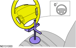
Steering wheel in straight ahead position.
General Equipment: Steering Wheel Holder.
- Remove the wheels and tires. For additional information, refer to Section 204-04.
- If equipped.
- To install, tighten to 70 Nm (52 lb-ft).
- If equipped.
Vehicles equipped with 3.5L GTDI
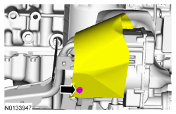
- Remove the RH and LH exhaust flexible pipes. For additional information, refer to Section 309-00.
Vehicles equipped with 3.5L Ti-VCT
- Remove the engine exhaust Y-pipe. For additional information, refer to Section 309-00.
All vehicles
- NOTICE: Do not allow the intermediate shaft to rotate
while it is disconnected from the gear or damage to the clockspring may
occur. If there is evidence that the intermediate shaft has rotated, the
clockspring must be removed and recentered. For additional information,
refer to Section 501-20B.
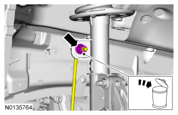
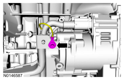
NOTE: Index-mark the steering column shaft position to the steering gear for reference during installation.
Discard the specified component. Follow local disposal regulations.- To install, tighten to 20 Nm (177 lb-in).
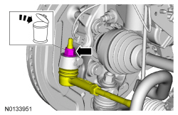
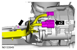
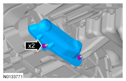
- NOTE: Use the hex-holding feature to prevent the stud from
turning while removing the nut.
On both sides. Discard the specified component. Follow local disposal regulations.
- To install, tighten to 150 Nm (111 lb-ft).
- NOTE: Use the hex-holding feature to prevent the stud from
turning while removing the nut.
On both sides. Discard the specified component. Follow local disposal regulations.
- To install, tighten to 150 Nm (111 lb-ft).
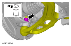
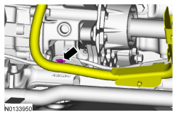
- NOTICE: Use care when releasing the lower arm and knuckle into
the resting position or damage to the ball joint seal or CV boot may occur.
NOTE: Use the hex-holding feature to prevent the stud from turning while removing the nut.
On both sides. Discard the specified component. Follow local disposal regulations.- To install, tighten to 200 Nm (148 lb-ft).
- If equipped.
-
- To install, tighten to 11 Nm (97 lb-in).
-
- To install, tighten to 11 Nm (97 lb-in).
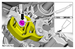
Vehicles equipped with 3.5L Ti-VCT
-
- To install, tighten to 9 Nm (80 lb-in).
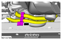
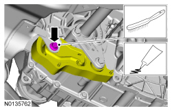
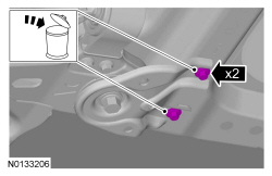
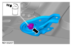
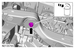
- Wire brush and apply the substance from the specified tube.
- To install, tighten to 103 Nm (76 lb-ft).
Vehicles equipped with 3.5L GTDI
- Wire brush and apply the substance from the specified tube.
- To install, tighten to 103 Nm (76 lb-ft).
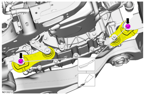
Vehicles equipped with 2.0L GTDI
- Wire brush and apply the substance from the specified tube.
- To install, tighten to 90 Nm (66 lb-ft).
All vehicles
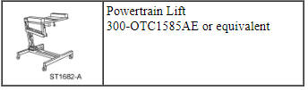
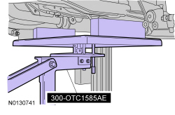
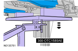
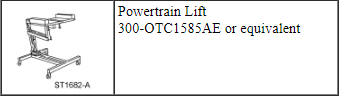
- General Equipment: Powertrain Lift 300-OTC-1585AE.
- On both sides. Discard the specified component. Follow local disposal
regulations.
- To install, tighten to 55 Nm (41 lb-ft).
- On both sides. Discard the specified component. Follow local disposal
regulations.
- To install, tighten to 200 Nm (148 lb-ft).
- On both sides. Discard the specified component. Follow local disposal
regulations.
- To install, tighten to 200 Nm (148 lb-ft).
- General Equipment: Powertrain Lift 300-OTC-1585AE.
Installation
- To install, reverse the removal procedure.
- Check the front end alignment and adjust as necessary. For additional information, refer to Section 204-00.
Subframe Bushings
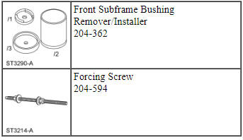
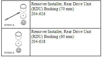
Special Tool(s)
Removal
- Remove the front subframe. For additional information, refer to Subframe - Front in this section.
- Assemble the Front Subframe Bushing Remover/Installer to the front subframe.
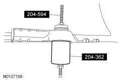
- Press out the subframe bushing.
Installation
- Assemble the Front Subframe Bushing Remover/Installer to the front subframe with the new subframe bushing.
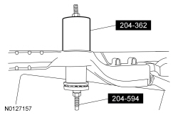
- Align the subframe bushing to the front subframe.
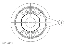
- Align the subframe bushing so that the voids are oriented in the fore-aft position.
- Press the new subframe bushing into the front subframe.
- Install the front subframe. For additional information, refer to Subframe - Front in this section.
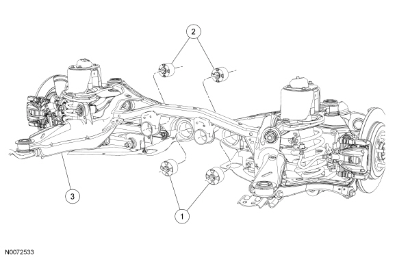
Subframe - Rear
Special Tool(s)
Removal and Installation
- Measure and record the vehicle ride height. For additional information, refer to Section 204-00.
- Remove the rear wheels. For additional information, refer to Section 204-04.
- With a wax pencil, mark the relational alignment of the rear subframe to the underbody at the mounting locations.
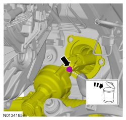
- NOTE: Index-mark the driveshaft before disconnecting from the
rear drive axle.
Remove and discard the 6 driveshaft bolts and position the driveshaft aside.
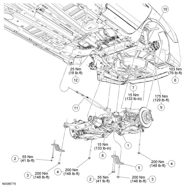
- To install, tighten the new bolts to 25 Nm (18 lb-ft).
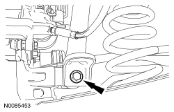
- Remove and discard the sway bar link upper nuts and reposition the sway bar.
- NOTE: Before tightening the lower shock bolts, use a jackstand to
raise the rear suspension until the distance between the center of the hub
and the lip of the fender is equal to the measurement taken in the Removal
procedure (curb height).
Remove the rear shock lower bolts.
- To install, tighten to 175 Nm (129 lb-ft).
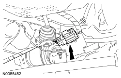
- Disconnect the main subframe electrical connector.
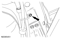
- Remove the intermediate park brake cable bracket bolt from the frame.
- To install, tighten to 15 Nm (133 lb-in).
- Disconnect the intermediate park brake cable from the front park brake cable.
- Remove the rear park brake cable bracket and reposition.
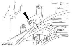
- Remove the wheel opening park brake cable bracket bolt and reposition the bracket.
- Remove the park brake cable from the caliper.
- Remove the brake caliper bolts.
- To install, tighten to 103 Nm (76 lb-ft).
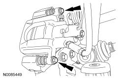
- NOTE: It is not necessary to disconnect the hydraulic brake
lines.
Remove the rear calipers and position aside. Attach to the body using mechanic's wire.
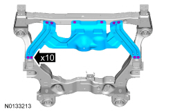
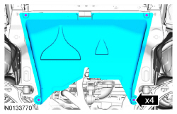
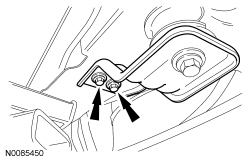
- Remove the 4 subframe bracket-to-body bolts. Discard the bolts.
- To install, tighten the new bolts to 55 Nm (41 lb-ft).
- NOTICE: When positioning the lifting table, be sure to support
the rear subframe on the subframe rails. Do not lift on the rear
differential or rear control arms, damage may occur.
Position the Powertrain Lift under the subframe.
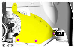
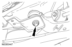
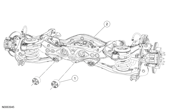
- Remove and discard the 2 rear subframe front mounting bolts.
- To install, tighten the new bolts to 200 Nm (148 lb-ft).
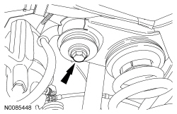
- Remove and discard the 2 rear subframe rear mounting bolts.
- To install, tighten the new bolts to 200 Nm (148 lb-ft).
- To install, reverse removal procedure.
Subframe Bushings - Rear Differential, Rear
Special Tool(s)
Removal
NOTE: There are 2 Rear Drive Unit (RDU) rear bushings in the rear subframe, this procedure shows how to remove one bushing. The procedure for the remaining RDU bushing is identical.
- Remove the RDU. For additional information, refer to Section 205-02.
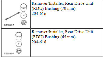
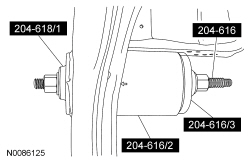
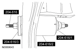
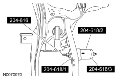
- NOTE: The Rear Drive Unit (RDU) Bushing Remover/Installer
204-618/1 must be used to remove the bushing to make sure that it passes
through the receiver cup.
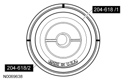
NOTE: Make sure the Rear Drive Unit (RDU) Bushing Remover/Installer 204-616/2 is positioned with the larger opening toward the bushing to act as the receiver cup.
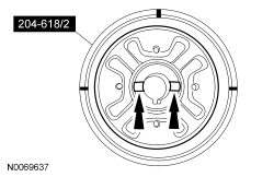
NOTE: Make sure the arrow on the Rear Drive Unit (RDU) Bushing Remover/Installers is pointed toward the rear subframe when removing the bushing.
Assemble the Rear Drive Unit (RDU) Bushing Remover/Installers to the rear subframe and press out the bushing.
Installation
NOTE: There are 2 RDU rear bushings in the subframe, this procedure shows how to install one bushing. The procedure for the remaining RDU bushing is identical.
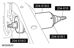
- NOTE: Make sure the alignment marks on the Rear Drive Unit (RDU)
Bushing Remover/Installers are aligned with the anti-rotation tabs on the RDU bushing.
Install the RDU bushing into the Rear Drive Unit (RDU) Bushing Remover/Installers.

- NOTE: Make sure the alignment marks are properly aligned on both
Rear Drive Unit (RDU) Bushing Remover/Installers and the anti-rotation tabs
are properly seated in the Rear Drive Unit (RDU) Bushing Remover/Installers.
Install the Rear Drive Unit (RDU) Bushing Remover/Installers onto the RDU bushing.

- NOTE: Make sure the arrow on the Rear Drive Unit (RDU) Bushing
Remover/Installers is visible on the bottom and facing away from the
subframe. The arrow must remain straight so that the bushings are correctly
indexed into the subframe.
NOTE: When installing the RDU bushing, Rear Drive Unit (RDU) Bushing Remover/Installers 204-616/2 will fall away as the RDU bushing is installed into the subframe. The Rear Drive Unit (RDU) Bushing Remover/Installers do not control the depth of the bushing. The RDU bushing is fully seated when the Rear Drive Unit (RDU) Bushing Remover/Installers fall away from the subframe, do not continue to tighten the Rear Drive Unit (RDU) Bushing Remover/Installers.
Install the RDU bushing into the subframe.
- Install the RDU. For additional information, refer to Section 205-02.
Subframe Bushings - Rear Differential, Front
Special Tool(s)
Removal
NOTE: There are 2 Rear Drive Unit (RDU) front bushings in the rear subframe, this procedure shows how to remove one bushing. The procedure for the remaining RDU bushing is identical.
- Remove the RDU. For additional information, refer to Section 205-02.
- NOTE: Make sure the Rear Drive Unit (RDU) Bushing
Remover/Installers are positioned with the larger opening toward the bushing
to act as the receiver cup.
NOTE: Make sure the arrow on the Rear Drive Unit (RDU) Bushing Remover/Installers is pointed toward the rear subframe when removing the bushing.
Assemble the Rear Drive Unit (RDU) Bushing Remover/Installer to the rear subframe and press out the bushing.
Installation
NOTE: There are 2 RDU front bushings in the subframe, this procedure shows how to install one bushing. The procedure for the remaining RDU bushing is identical.
- NOTE: Make sure the alignment marks on the Rear Drive Unit (RDU)
Bushing Remover/Installers are aligned with the anti-rotation tabs on the RDU bushing.
Install the RDU bushing into the Rear Drive Unit (RDU) Bushing Remover/Installer.
- NOTE: Make sure the alignment marks are properly aligned on the
Rear Drive Unit (RDU) Bushing Remover/Installer and the anti-rotation tabs
are properly seated in the Rear Drive Unit (RDU) Bushing Remover/Installer.
Install the Rear Drive Unit (RDU) Bushing Remover/Installer onto the RDU bushing.
- NOTE: Make sure the arrow on the Rear Drive Unit (RDU) Bushing
Remover/Installers is visible on the bottom and facing away from the
subframe. The arrow must remain straight so that the bushings are correctly
indexed into the subframe.
NOTE: When installing the RDU bushing, the Rear Drive Unit (RDU) Bushing Remover/Installers will fall away as the RDU bushing is installed into the subframe. The Rear Drive Unit (RDU) Bushing Remover/Installers do not control the depth of the bushing. The RDU bushing is fully seated when the Rear Drive Unit (RDU) Bushing Remover/Installer falls away from the subframe. Do not continue to tighten the Rear Drive Unit (RDU) Bushing Remover/Installer.
Install the RDU bushing into the subframe.
- Install the RDU. For additional information, refer to Section 205-02.