
SPECIFICATIONS
Material
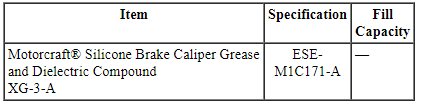
General Specifications
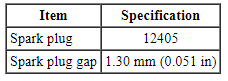
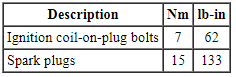
Torque Specifications
DESCRIPTION AND OPERATION
Engine Ignition
Component Location
3.7L Ti-VCT
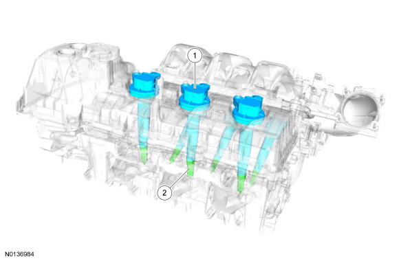
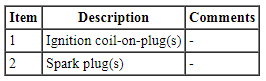
System Operation
REFER to the PC/ED manual section 1 Description and Operation.
Component Description
REFER to the PC/ED manual section 1 Description and Operation.
DIAGNOSIS AND TESTING
Engine Ignition
For PCM DTCs, REFER to Section 303-14 PCM DTC Chart. For driveability symptoms without DTCs, refer to the PC/ED manual, section 3 Symptom Charts.
REMOVAL AND INSTALLATION
Ignition Coil-On-Plug
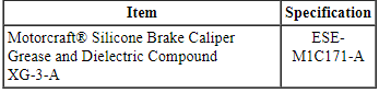
Material
Removal and Installation
RH side
NOTE: Removal steps in this procedure may contain installation details.
- NOTE: The upper intake manifold must be removed to access the RH
ignition coil-on-plugs.
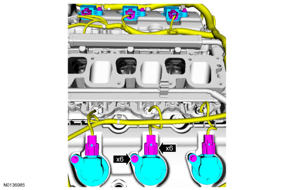
Remove the upper intake manifold. For additional information, refer to Section 303-01D.
Both sides
- NOTE: When removing the ignition coil-on-plugs, a slight twisting
motion will break the seal and ease removal.
NOTE: Before installing the ignition coil-on-plug apply a small amount of dielectric grease to the inside of the ignition coil-on-plug boots.
- Tighten to 7 Nm (62 lb-in).
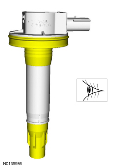
- Inspect the ignition coil-on-plug rubber seals and boots for cracks, rips, or tears. Replace any damaged coil-on-plug rubber seals or boots.
- To install, reverse the removal procedure.
Spark Plugs
Removal and Installation
NOTE: Removal steps in this procedure may contain installation details.
- Remove the 6 ignition coil-on-plugs. For additional information, refer to Ignition Coil-On-Plug.
- NOTICE: Only use hand tools when removing or installing the
spark plugs or damage can occur to the cylinder head or spark plug.
NOTICE: The spark plug procedure must be followed exactly or damage to the cylinder head and spark plug will result.
NOTICE: Do not remove the spark plugs when the engine is hot or cold soaked. Spark plug thread or cylinder head damage can occur. Make sure the engine is warm (hand touch after cooling down) prior to spark plug removal.
NOTE: Use compressed air to remove any foreign material in the spark plug well before removing the spark plugs.
- Tighten to 15 Nm (133 lb-in).
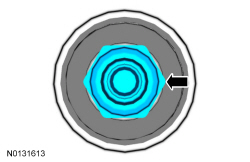
- Inspect the spark plugs. For additional information, refer to Section 303-00.
- To install, reverse the removal procedure.
 Engine Ignition - 2.0L GTDI
SPECIFICATIONS
Material
General Specifications
Torque Specifications
DESCRIPTION AND OPERATION
Engine Ignition
Component Location
System Operation
REFER to the PC/ED manual
sect ...
 Engine Emission Control
SPECIFICATIONS
Material
Torque Specifications
DESCRIPTION AND OPERATION
Engine Emission Control
Component Locations
2.0L GTDI
3.5L Ti-VCT and
3.7L Ti-VCT
3.5L GTDI
S ...
Other materials:
Power windows
WARNING: Do not leave children unattended in your vehicle
and do not let children play with the power windows. They may
seriously injure themselves.
WARNING: When closing the power windows, you should verify
they are free of obstructions and make sure that children and
pets are not in the proxi ...
Adjusting the steering wheel
WARNING: Do not adjust the steering wheel when your vehicle
is moving.
Note: Make sure that you are sitting in the correct position. See
Sitting
in the Correct Position in the Seats chapter.
1. Unlock the steering column.
2. Adjust the steering wheel to the
desired position.
3. Lock t ...
Dual automatic temperature control
Note: You can switch temperature units between Fahrenheit and Celsius.
See Menu features in the MyFord Touch or MyLincoln Touch chapter.
A. Power/Driver temperature control: Press to turn the climate
control system off and on. When the system is off, outside air cannot
enter the vehicle.
...
