Engine
Special Tool(s)
Material
NOTICE: During engine repair procedures, cleanliness is extremely important. Any foreign material, including any material created while cleaning gasket surfaces that enters the oil passages, coolant passages or the oil pan, can cause engine failure.
NOTE: If the cylinder head(s) is replaced, a new secondary timing chain tensioner will need to be installed.
NOTE: For additional information, refer to the exploded view under the Assembly procedure in this section.
All vehicles
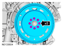
- Remove the 8 bolts and the flexplate.
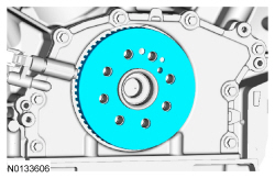
- Remove the crankshaft sensor ring.
- NOTICE: Install the engine stand bolts into the cylinder block
only. Do not install the bolts into the oil pan.
Mount the engine on a suitable engine stand.
- If equipped, remove the block heater heat shield.
- If equipped, disconnect the block heater electrical connector.
- Remove the block heater wiring harness from the engine.
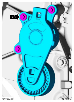
- Remove the 3 bolts and the accessory drive belt tensioner.
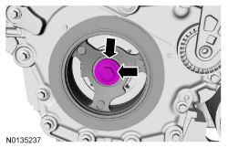
- Remove the crankshaft pulley bolt and washer.
- Discard the bolt.
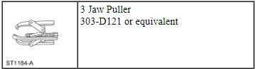
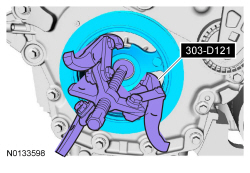
- Using the 3 Jaw Puller, remove the crankshaft pulley.
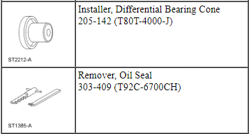
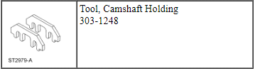
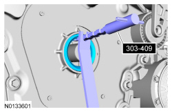
- Using the Oil Seal Remover, remove and discard the crankshaft front seal.
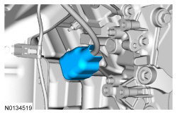
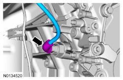
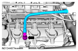
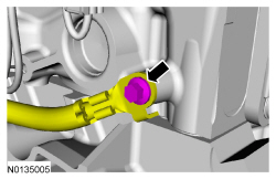
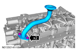
- Remove the crankcase vent tube. For additional information, refer to the quick connect coupling procedure in Section 310-00.
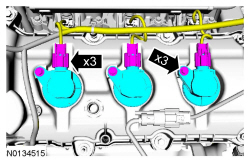
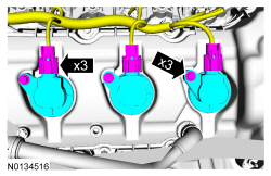
- NOTE: When removing the ignition coil-on-plugs, a slight twisting
motion will break the seal and ease removal.
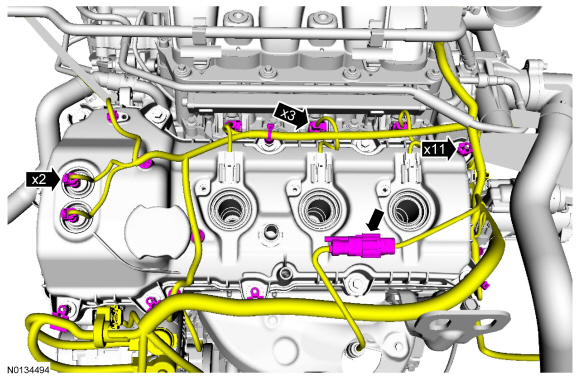
Disconnect the 3 LH coil-on-plug electrical connectors and remove the 3 bolts and the 3 LH-coil-on-plugs.
- Inspect the coil seals for rips, nicks or tears. Remove and discard any damaged coil seals.
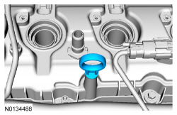
- Remove the oil level indicator.
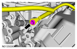
- Remove the bolt and wire harness ground from the engine front cover.
- Remove the engine wiring harness from the LH valve cover.
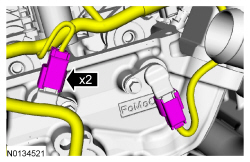
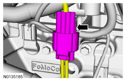
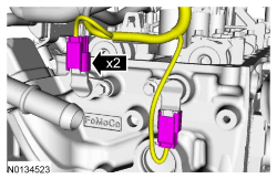
- Disconnect the 2 Variable Camshaft Timing (VCT) oil control solenoid electrical connectors.
- Detach and disconnect the LH Heated Oxygen Sensor (HO2S) electrical connector.
- Disconnect the 3 fuel injector electrical connectors.
- Detach the 11 wiring harness retainers from the LH valve cover and stud bolts and position the harness aside.
- Disconnect the 2 LH Camshaft Position (CMP) sensor electrical connectors.
- Remove the wiring harness retainer from the rear of the LH cylinder head.
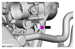
- Disconnect the Evaporative Emission (EVAP) canister vent solenoid and
throttle body electrical connectors.
- Detach the wiring harness pin-type retainer from the upper intake manifold.
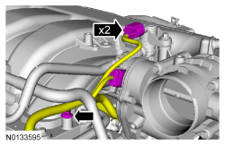
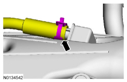
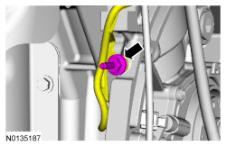
- Disconnect the EVAP vapor tube from the EVAP canister vent solenoid. For
additional information, refer to Section 310-00.
- Detach the EVAP vapor tube from the 2 retainers.
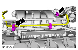
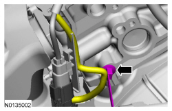
- Disconnect the crankcase ventilation hose from the upper intake manifold.
- Detach the 2 coolant tube retainers from the upper intake manifold.
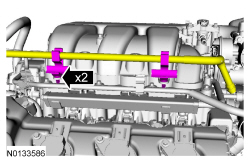
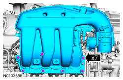
- Remove the upper intake manifold support bracket bolt.
- Remove the 7 bolts and the upper intake manifold.
- Remove and discard the gasket.
- Clean and inspect all of the sealing surfaces of the upper and lower intake manifold.
- NOTE: When removing the ignition coil-on-plugs, a slight twisting
motion will break the seal and ease removal.
Disconnect the 3 RH coil-on-plug electrical connectors and remove the 3 bolts and the 3 RH coil-on-plugs.
- Inspect the coil seals for rips, nicks or tears. Remove and discard any damaged coil seals.
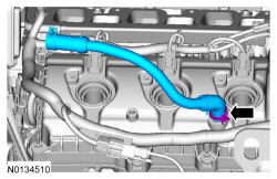
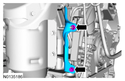
- Remove the PCV crankcase vent tube.
- NOTE: On All-Wheel Drive (AWD) vehicles the Catalyst Monitor
Sensor (CMS) electrical connector was disconnected during the engine removal
procedure.
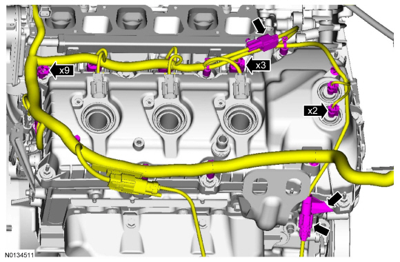
Remove the engine wiring harness from the RH valve cover.
- Disconnect the 2 Variable Camshaft Timing (VCT) oil control solenoid electrical connectors.
- Detach and disconnect the RH Catalyst Monitor Sensor (CMS) electrical connector.
- Disconnect the 3 fuel injector electrical connectors.
- Disconnect the Cylinder Head Temperature (CHT) sensor wiring harness jumper electrical connector.
- Detach the 9 wiring harness retainers from the RH valve cover and stud bolts and position the harness aside.
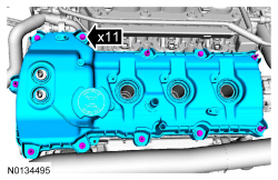
- NOTICE: While removing the valve cover do not apply excessive
force to the Variable Camshaft Timing (VCT) oil control solenoid or damage
may occur.
NOTICE: If the Variable Camshaft Timing (VCT) oil control solenoid sticks to the VCT seal, carefully wiggle the valve cover until the bond breaks free or damage to the VCT seal and VCT oil control solenoid may occur.
Loosen the 4 bolts and 7 stud bolts.- Remove the LH valve cover.
- Discard the gasket.
- Inspect the VCT solenoid seals. Remove any damaged seals.
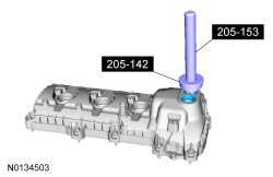
- Using the Differential Bearing Cone Installer and Handle, remove and discard the seal(s).
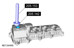
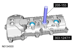
- Inspect the spark plug tube seals. Remove any damaged seals.
- Using the Spark Plug Tube Seal Remover and Handle, remove and discard the seal(s).
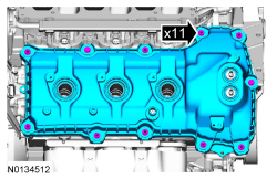
- NOTICE: While removing the valve cover do not apply excessive
force to the Variable Camshaft Timing (VCT) oil control solenoid or damage
may occur.
NOTICE: If the Variable Camshaft Timing (VCT) oil control solenoid sticks to the VCT seal, carefully wiggle the valve cover until the bond breaks free or damage to the VCT seal and VCT oil control solenoid may occur.
Loosen the 3 bolts and 8 stud bolts.- Remove the RH valve cover.
- Discard the gasket.
- Inspect the 2 VCT solenoid seals. Remove any damaged seals.
- Using the Differential Bearing Cone Installer and Handle, remove the seal(s).
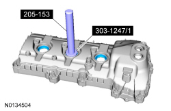
- Inspect the spark plug tube seals. Remove any damaged seals.
- Using the VCT Spark Plug Tube Seal Remover and Handle, remove the seal(s).
- Clean the valve covers, cylinder heads and engine front cover sealing surfaces with metal surface prep.
- Disconnect the Knock Sensor (KS) electrical connector.
- Disconnect the 2 RH Camshaft Position Camshaft Position (CMP) sensor electrical connectors.
- Remove the bolt and the ground cable from the RH cylinder head.
- Remove the nut, the bolt and the heat shield.
- Remove the wiring harness retainer stud bolt.
- Remove the wiring harness grommet.
- Disconnect the Crankshaft Position (CKP) sensor electrical connector.
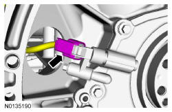
- Remove the bolt and the CKP sensor.
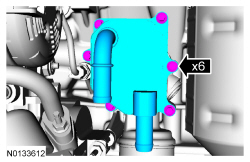
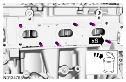
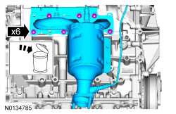
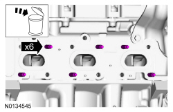
- NOTICE: If metal or aluminum material is present in the
oil cooler, mechanical concerns exist. Failure to correct these concerns may
cause engine failure. To diagnose mechanical concerns, refer to Section
303-00.
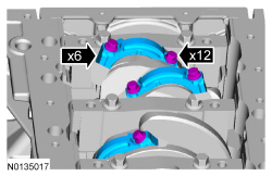
If equipped, remove the 6 bolts and the oil cooler.
- Discard the gaskets.
- Clean and inspect all sealing surfaces.
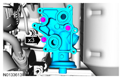
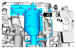
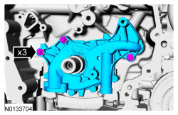
- NOTE: Oil filter adapter with oil cooler shown, oil filter
adapter without oil cooler similar.
Remove the 3 bolts and the oil filter adapter.
- Discard the gasket.
- Clean and inspect all sealing surfaces.
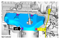
- Disconnect the 2 A/C compressor electrical connectors.
- Detach the A/C wiring harness retainer.
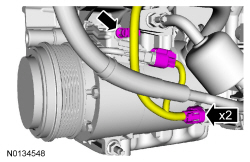
- Remove the nut, 2 stud bolts and the A/C compressor.
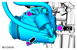
- Remove the A/C compressor mounting stud from the oil pan.
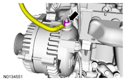
- Disconnect the generator electrical connector and position the generator B+ cable cover aside.
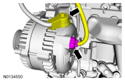
- Remove the nut and disconnect the generator B+ cable.
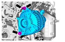
- Remove the nut, bolt and the generator.
- Remove the generator stud.
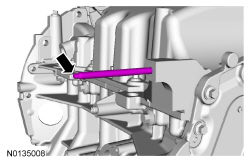
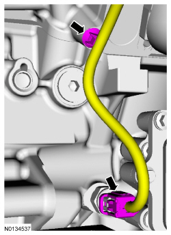
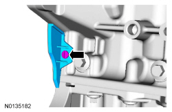
- Disconnect the Engine Oil Pressure (EOP) switch electrical connector and
the wiring harness pin-type retainer.
- Remove the wiring harness from the engine.
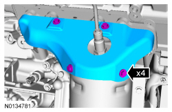
- Remove the 3 bolts and the LH exhaust heat shield.
- Remove the 6 nuts and the LH catalytic converter manifold.
- Discard the nuts and LH catalytic converter manifold gasket.
- Clean and inspect the catalytic converter flange. For additional information, refer to exhaust manifold cleaning and inspection in Section 303-00.
- Remove and discard the 6 LH exhaust manifold studs.
Front Wheel Drive (FWD) vehicles
- Remove the 4 bolts and the RH catalytic converter heat shield.
- Remove the 6 nuts and the RH catalytic converter manifold.
- Discard the nuts and RH catalytic converter manifold gasket.
- Clean and inspect the RH catalytic converter manifold. For additional information, refer to Section 303-00.
- Remove and discard the 6 RH exhaust manifold studs.
All vehicles
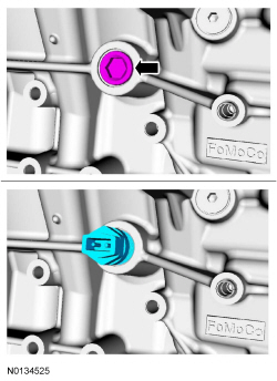
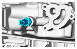
- Remove the RH cylinder block drain plug or, if equipped, the block
heater.
- Allow coolant to drain from the cylinder block.
- Remove the LH cylinder block drain plug.
- Allow coolant to drain from the cylinder block.
- Remove the pin-type retainer and the cover.
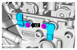
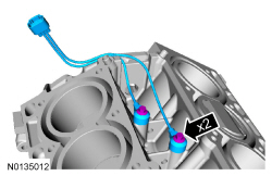
- Remove the 2 bolts and the 2 LH CMP sensors.
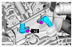
- Remove the 2 bolts and the 2 RH CMP sensors.
- Remove the 2 thermostat housing-to-lower intake manifold bolts.
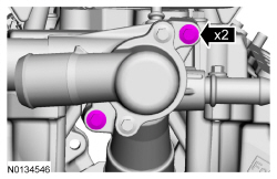
- Remove the fuel supply tube-to-engine front cover bolt.
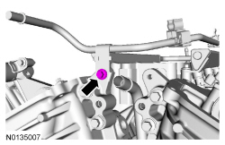
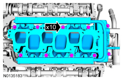
- NOTICE: If the engine is repaired or replaced because of upper
engine failure, typically including valve or piston damage, check the intake
manifold for metal debris. If metal debris is found, install a new intake
manifold. Failure to follow these instructions can result in engine damage.
Remove the 10 bolts and the lower intake manifold.
- Remove and discard the intake manifold and thermostat housing gaskets.
- Clean and inspect all sealing surfaces.
- Disconnect and remove the CHT sensor jumper harness.
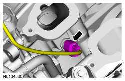
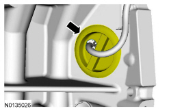
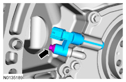
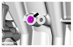
- Remove the EOP switch.
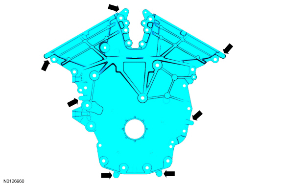
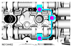
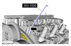
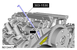
- Remove the 26 front cover bolts.
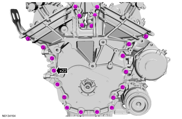
- Using a suitable pry tool, locate the 7 pry pads shown and pry the engine front cover loose and remove.
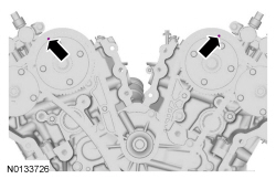
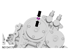
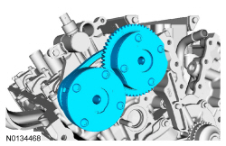
- Rotate the crankshaft clockwise and align the timing marks on the intake Variable Camshaft Timing (VCT) assemblies as shown.
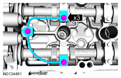
- Remove the 3 bolts and the LH valve train oil tube.
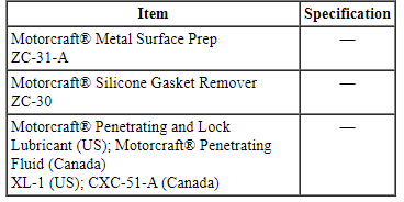
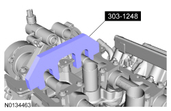
- NOTE: The Camshaft Holding Tool will hold the camshafts in the
Top Dead Center (TDC) position.
Install the Camshaft Holding Tool onto the flats of the LH camshafts.
- Remove the 3 bolts and the RH valve train oil tube.
- NOTE: The Camshaft Holding Tool will hold the camshafts in
the TDC position.
Install the Camshaft Holding Tool onto the flats of the RH camshafts.

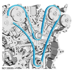
NOTE: The following 3 steps are for primary timing chains that the colored links are not visible.
- Mark the timing chain link that aligns with the timing mark on the LH intake VCT assembly as shown.
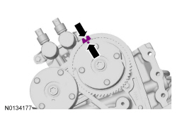
- Mark the timing chain link that aligns with the timing mark on the RH intake VCT assembly as shown.
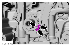
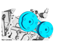
- NOTE: The crankshaft sprocket timing mark should be between the 2
colored links.
Mark the 2 timing chain links that align with the timing mark on the crankshaft sprocket as shown.
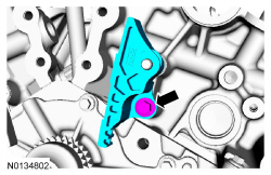
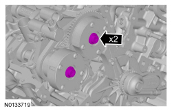
- Remove the 2 bolts and the primary timing chain tensioner.
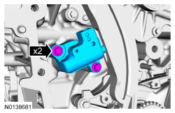
- Remove the primary timing chain tensioner arm.
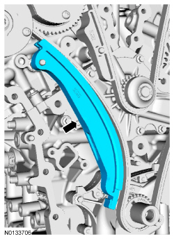
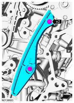
- Remove the 2 bolts and the lower LH primary timing chain guide.
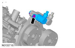
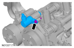
- NOTE: Removal of the VCT oil control solenoid will aid in the
removal of the primary timing chain.
NOTE: A slight twisting motion will aid in the removal of the VCT oil control solenoid.
NOTE: Keep the VCT oil control solenoid clean of dirt and debris.
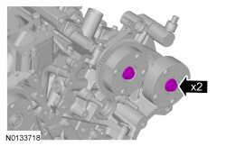
Remove the bolt and the LH intake VCT oil control solenoid.
- NOTE: Removal of the VCT oil control solenoid will aid in the
removal of the primary timing chain.
NOTE: A slight twisting motion will aid in the removal of the VCT oil control solenoid.
NOTE: Keep the VCT oil control solenoid clean of dirt and debris.
Remove the bolt and the RH intake VCT oil control solenoid.
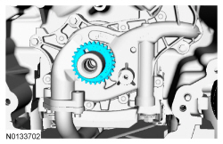
- Remove the primary timing chain.
- Remove the crankshaft timing chain sprocket.
- NOTICE: Do not use power tools to remove the bolt or damage to
the LH primary timing chain guide may occur.
Remove the bolt and the upper LH primary timing chain guide.
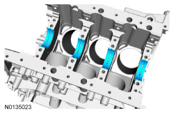
- NOTE: The 2 VCT oil control solenoids are removed for clarity.
NOTE: The Secondary Chain Hold Down is inserted through a hole in the top of the mega cap.
Compress the LH secondary timing chain tensioner and install the Secondary Chain Hold Down in the hole on the rear of the secondary timing chain tensioner guide and let it hold against the mega cap to retain the tensioner in the collapsed position.
- Remove and discard the 2 LH VCT assembly bolts.
- Remove the 2 LH VCT assemblies and secondary timing chain.
- NOTE: When the Camshaft Holding Tool is removed, valve spring
pressure may rotate the LH camshafts approximately 3 degrees to a neutral
position.
Remove the Camshaft Holding Tool from the LH camshafts.

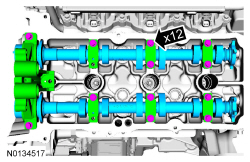
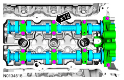
- NOTE: Cylinder head camshaft bearing caps are numbered to verify
that they are assembled in their original positions.
NOTE: Mark the exhaust and intake camshafts for installation into their original locations.
Remove the 12 bolts, 6 camshaft caps, mega cap and the LH camshafts.
- NOTE: The 2 VCT oil control solenoids are removed for clarity.
NOTE: The Secondary Chain Hold Down is inserted through a hole in the top of the mega cap.
Compress the RH secondary timing chain tensioner and install the Secondary Chain Hold Down in the hole on the rear of the secondary timing chain tensioner guide and let it hold against the mega cap to retain the tensioner in the collapsed position.
- Remove and discard the 2 RH VCT assembly bolts.
- Remove the 2 RH VCT assemblies and secondary timing chain.
- Remove the Secondary Chain Hold Down.
- NOTE: When the Camshaft Holding Tool is removed, valve spring
pressure may rotate the RH camshafts approximately 3 degrees to a neutral
position.
Remove the Camshaft Holding Tool from the RH camshafts.
- NOTE: Cylinder head camshaft bearing caps are numbered to verify
that they are assembled in their original positions.
NOTE: Mark the exhaust and intake camshafts for installation into their original locations.
Remove the 12 bolts, 6 camshaft caps, mega cap and the RH camshafts.
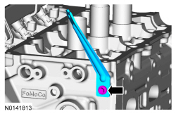
- NOTICE: Do not use power tools to remove the bolt or damage to
the RH primary timing chain guide may occur.
Remove the bolt and the RH primary timing chain guide.
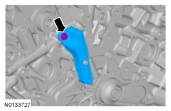
- Remove the 2 bolts and the engine lifting eye.
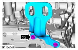
- NOTE: Index-mark the location of the bracket on the cylinder head
for installation.
Remove the bolt and the upper intake manifold bracket.
- NOTE: If the components are to be reinstalled, they must be
installed in the same positions. Mark the components for installation into
their original locations.
NOTE: LH shown, RH similar.
Remove the 24 valve tappets from the cylinder heads.
- NOTE: LH shown, RH similar.
Remove and discard the M6 bolt.
- NOTICE: Place clean, lint-free shop towels over exposed engine
cavities. Carefully remove the towels so foreign material is not dropped
into the engine. Any foreign material (including any material created while
cleaning gasket surfaces) that enters the oil passages or the oil pan, may
cause engine failure.
NOTICE: Aluminum surfaces are soft and can be scratched easily. Never place the cylinder head gasket surface, unprotected, on a bench surface.
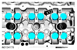
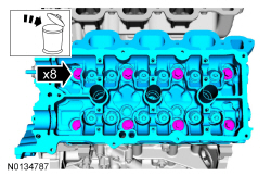
NOTE: The cylinder head bolts must be discarded and new bolts must be installed. They are tighten-to-yield designed and cannot be reused.
NOTE: LH shown, RH similar.
Remove and discard the 8 bolts from the cylinder heads.- Remove the LH and RH cylinder heads.
- Discard the cylinder head gaskets.
- NOTICE: Do not use metal scrapers, wire brushes, power
abrasive discs or other abrasive means to clean the sealing surfaces. These
tools cause scratches and gouges that make leak paths. Use a plastic
scraping tool to remove all traces of the head gasket.
NOTE: Observe all warnings or cautions and follow all application directions contained on the packaging of the silicone gasket remover and the metal surface prep.
NOTE: If there is no residual gasket material present, metal surface prep can be used to clean and prepare the surfaces.
Clean the cylinder head-to-cylinder block mating surfaces of both the cylinder heads and the cylinder block in the following sequence.- Remove any large deposits of silicone or gasket material with a plastic scraper.
- Apply silicone gasket remover, following package directions, and allow to set for several minutes.
- Remove the silicone gasket remover with a plastic scraper. A second application of silicone gasket remover may be required if residual traces of silicone or gasket material remain.
- Apply metal surface prep, following package directions, to remove any remaining traces of oil or coolant and to prepare the surfaces to bond with the new gasket. Do not attempt to make the metal shiny. Some staining of the metal surfaces is normal.
- Make sure the 2 locating dowel pins are seated correctly in the cylinder block.
- Support the cylinder head on a bench with the head gasket side up. Check the cylinder head distortion and the cylinder block distortion. For additional information, refer to Section 303-00.
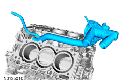
- Remove the coolant inlet tube and thermostat assembly.
- Remove and discard the O-ring seal.
- Remove the 2 bolts and the KS.
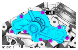
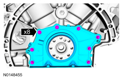
- Remove the 8 bolts and the coolant pump.
- Remove the 16 oil pan bolts.
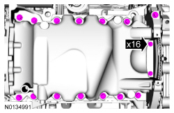
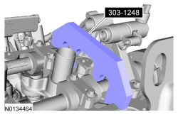
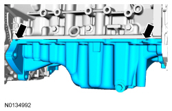
- Using a suitable pry tool, locate the pry pads and pry the oil pan loose and remove.
- Remove the 2 bolts and the oil pump screen and pickup tube.
- Discard the O-ring seal.
- Remove the 3 bolts and the oil pump.
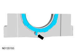
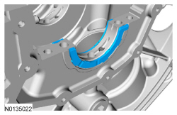
- Remove the 8 bolts and the crankshaft rear seal retainer plate.
- Discard the plate and seal assembly.
- NOTICE: Only use a 3M Roloc Bristle Disk (2-in white, part
number 07528) to clean the engine front cover, oil pan and crankshaft rear
seal retainer plate. Do not use metal scrapers, wire brushes or any other
power abrasive disk to clean the engine front cover and oil pan. These tools
cause scratches and gouges that make leak paths.
Clean the engine front cover and oil pan using a 3M Roloc Bristle Disk (2 inch, white, part number 07528) in a suitable tool turning at the recommended speed of 15,000 rpm.
- Thoroughly wash the engine front cover and oil pan to remove any foreign material, including any abrasive particles created during the cleaning process.
- Before removing the pistons, inspect the top of the cylinder bores. If necessary, remove the ridge or carbon deposits from each cylinder using an abrasive pad or equivalent, following manufacturer's instructions.
- NOTE: The main bearing cap support brace bolts must be discarded
and new bolts must be installed. They are a tighten-to-yield design and
cannot be reused.
Remove the bolts in the sequence shown.
- Remove the main bearing cap support brace.
- Discard the bolts.
- NOTE: The connecting rod cap bolts are a torque-to-yield design.
The original connecting rod cap bolts will be used when measuring the
connecting rod large end bore during assembly. The connecting rod cap bolts
will be discarded after measurement.
NOTE: Clearly mark the position and orientation of the connecting rods, connecting rod caps and connecting rod bearings for reassembly.
Remove the 12 connecting rod cap bolts and 6 cap.
- NOTICE: Do not scratch the cylinder walls or crankshaft
journals with the connecting rod.
Remove the piston/rod assembly from the engine block.
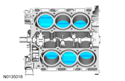
- Repeat the previous step until all the piston/rod assemblies are removed from the engine block.
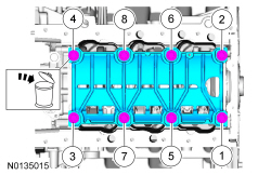
- NOTE: The 8 main bearing cap side bolts and the 8 main bearing
cap bolts must be discarded and new bolts must be installed. They are a
tighten-to-yield design and cannot be reused.
NOTE: Clearly mark the position and orientation of the main bearing caps for reassembly.
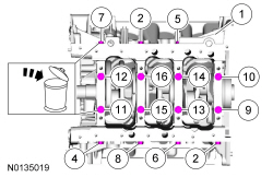
Remove the 8 main bearing cap side bolts and the 8 main bearing cap bolts in the sequence shown.- Discard the bolts.
- NOTE: If the main bearings are being reused, mark them for
correct position and orientation for reassembly.
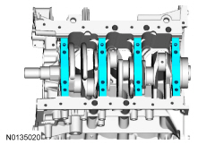
NOTE: Note the position of the thrust washer on the outside of the No. 4 rear main bearing cap.
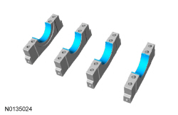
Remove the 4 main bearing caps.
- Remove the lower crankshaft thrust washer from the back side of the No. 4 rear main bearing cap.
- NOTE: If the main bearings are being reused, mark them for
correct position and orientation for reassembly.
Remove the 4 crankshaft main bearings from the main bearing caps.
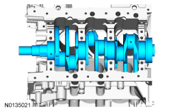
- NOTE: Note the position of the 2 thrust washers on the inside and
outside of the rear main bearing bulkhead.
Remove the crankshaft.
- Remove the 2 crankshaft thrust bearings from the rear main bearing bulkhead.
- NOTE: If the main bearings are being reused, mark them for
correct position and orientation for reassembly.
Remove the 4 crankshaft main bearings from the cylinder block.
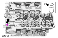
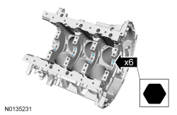
- Using a hexagonal screwdriver, remove the 6 piston oil cool valves.
- Inspect the cylinder block, bearing cap support brace, pistons and connecting rods. For additional information, refer to Section 303-00.
- NOTICE: Place clean, lint-free shop towels over exposed engine
cavities. Carefully remove the towels so foreign material is not dropped
into the engine. Any foreign material (including any material created while
cleaning gasket surfaces) that enters the oil passages or the oil pan, may
cause engine failure.
NOTICE: Do not use wire brushes, power abrasive discs or 3M Roloc Bristle Disk (2-in white part number 07528) to clean the sealing surfaces. These tools cause scratches and gouges that make leak paths. They also cause contamination that will cause premature engine failure. Remove all traces of the gasket.
Clean the sealing surfaces of the cylinder block in the following sequence.- Remove any large deposits of silicone or gasket material.
- Apply silicone gasket remover and allow to set for several minutes.
- Remove the silicone gasket remover. A second application of silicone gasket remover may be required if residual traces of silicone or gasket material remain.
- Apply metal surface prep to remove any remaining traces of oil or coolant and to prepare the surfaces to bond. Do not attempt to make the metal shiny. Some staining of the metal surfaces is normal.
- Make sure the 2 locating dowel pins are seated correctly in the cylinder block.
 Removal
Engine
Special Tool(s)
WARNING: Do not smoke, carry lighted tobacco or have an open flame of any
type when working on or near any fuel-related component. Highly flammable
mixtures are always prese ...
 Disassembly and Assembly of Subassemblies
Cylinder Head
Special Tool(s)
Material
Cylinder Head
NOTE: RH shown, LH similar.
Disassembly
All cylinder heads
NOTE: If the components are to be reinstalled, they must be installed
in ...
Other materials:
Sunshade
The power rear sunshade covers the rear window of the vehicle.
The control is located in the center
console access bin.
Press the control to move the sunshade up or down.
Note: Do not try to manually move the sunshade.
The sunshade has a one-touch down feature. Press and release the
cont ...
General Procedures
Headlamp Adjustment
Special Tool(s)
Headlamp Adjustment Screw Location
Headlamp Aiming
The headlamp aiming procedure depends on what type of beam pattern the
headlamp is equipped with. Vehicles may come equipped with visually
optically aligned left (VOL) or visually optically aligned right ( ...
Assembly
Engine
Special Tool(s)
Material
Engine Upper
Engine Front
Engine Upper - LH Cylinder Head
Engine Upper - RH Cylinder Head
Timing Drive Components
Lower Engine Block (View 1)
Lower Engine Block (View 2)
NOTICE: During engine repair procedures, cleanliness is extremely
i ...
