External Controls
Inspection and Verification
- Verify the customer concern by operating the system.
- Visually inspect for obvious signs of mechanical or electrical damage.
- If the concern is not visually evident, verify the symptom. GO to Symptom Chart.
Visual Inspection Chart
DTC Chart
Diagnostics in this manual assume a certain skill level and knowledge of Ford-specific diagnostic practices. Refer to Diagnostic Methods in Section 100-00 for information about these practices.
DTC Chart - BCM
DTC Chart - PCM
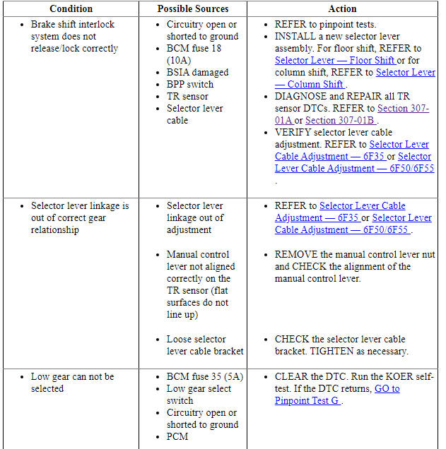
Symptom Chart
Diagnostics in this manual assume a certain skill level and knowledge of Ford-specific diagnostic practices. Refer to Diagnostic Methods in Section 100-00 for information about these practices.
In most circumstances, the PCM sets DTCs to help guide with diagnostics. Refer to the DTC Chart before using the symptom chart. The Condition column lists the vehicle condition. The Source column lists a detailed vehicle condition. The Action column lists the action to be performed to determine the cause of the condition. Each action lists the components that can caused the system and the individual components in that system. The components are listed in order of disassembly. Use the list of components and the required action to focus on disassembly inspections for the root cause of the concern.
Pinpoint Tests
Pinpoint Test A: B1319:11 (Floor Shift)
Diagnostic Overview
Diagnostics in this manual assume a certain skill level and knowledge of Ford-specific diagnostic practices. Refer to Diagnostic Methods in Section 100-00 for information about these practices.
Refer to Wiring Diagrams Cell 37 , Shift Interlock for schematic and connector information.
Normal Operation and Fault Conditions
The BSIA system is controlled by the BCM and is activated when the BCM receives a brake pedal applied input.
DTC Fault Trigger Conditions
-
Possible Sources
- Connectors damaged or pushed-out terminals, corrosion, loose wires and missing or damaged seals.
- BSIA solenoid
- Fuse
- BCM
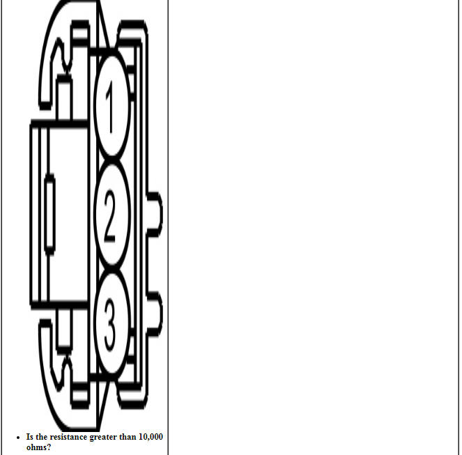
PINPOINT TEST A: B1319:11 (FLOOR SHIFT)
Pinpoint Test B: B1319:15 (Floor Shift)
Diagnostic Overview
Diagnostics in this manual assume a certain skill level and knowledge of Ford-specific diagnostic practices. Refer to Diagnostic Methods in Section 100-00 for information about these practices.
Refer to Wiring Diagrams Cell 37 , Shift Interlock for schematic and connector information.
Normal Operation and Fault Conditions
The BSIA system is controlled by the BCM and is activated when the BCM receives a brake pedal applied input.
DTC Fault Trigger Conditions
-
Possible Sources
- Connectors damaged or pushed-out terminals, corrosion, loose wires and missing or damaged seals.
- BSIA solenoid
- Fuse
- BCM
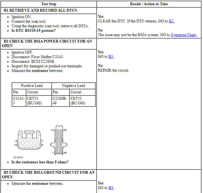
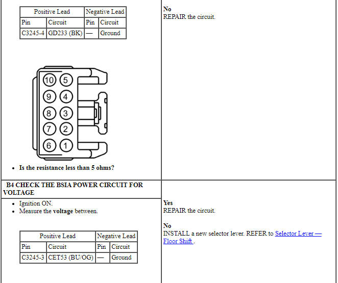
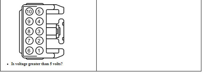
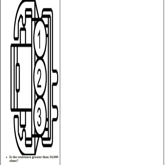
PINPOINT TEST B: B1319:15 (FLOOR SHIFT)
Pinpoint Test C: B1319:11 (Column Shift)
Diagnostic Overview
Diagnostics in this manual assume a certain skill level and knowledge of Ford-specific diagnostic practices. Refer to Diagnostic Methods in Section 100-00 for information about these practices.
Refer to Wiring Diagrams Cell 37 , Shift Interlock for schematic and connector information.
Normal Operation and Fault Conditions
The BSIA system is controlled by the BCM and is activated when the BCM receives a brake pedal applied input.
DTC Fault Trigger Conditions
-
Possible Sources
- Connectors damaged or pushed-out terminals, corrosion, loose wires and missing or damaged seals.
- BSIA solenoid
- Fuse
- BCM
PINPOINT TEST C: B1319:11 (COLUMN SHIFT)
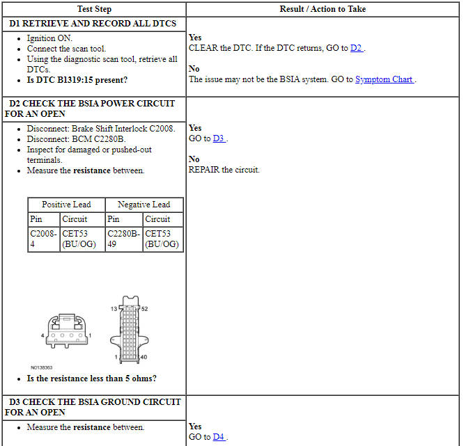
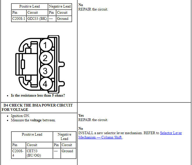
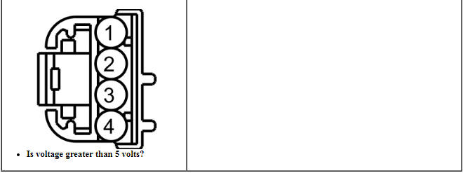
Pinpoint Test D: B1319:15 (Column Shift)
Diagnostic Overview
Diagnostics in this manual assume a certain skill level and knowledge of Ford-specific diagnostic practices. Refer to Diagnostic Methods in Section 100-00 for information about these practices.
Refer to Wiring Diagrams Cell 37 , Shift Interlock for schematic and connector information.
Normal Operation and Fault Conditions
The BSIA system is controlled by the BCM and is activated when the BCM receives a brake pedal applied input.
DTC Fault Trigger Conditions
-
Possible Sources
- Connectors damaged or pushed-out terminals, corrosion, loose wires and missing or damaged seals.
- BSIA solenoid
- Fuse
- BCM
PINPOINT TEST D: B1319:15 (COLUMN SHIFT)
Pinpoint Test E: P0815, P0816 (Floor Shift)
Diagnostic Overview
Diagnostics in this manual assume a certain skill level and knowledge of Ford-specific diagnostic practices. Refer to Diagnostic Methods in Section 100-00 for information about these practices.
Refer to Wiring Diagrams Cell 29 , Transmission Controls - 6 Speed for schematic and connector information.
Normal Operation and Fault Conditions
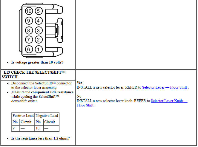
The SelectShift switch is a toggle switch integral to the selector lever knob. When the selector lever is placed in the manual shift position, the upshift/downshift feature becomes activated. If a new switch is required install a new selector lever knob.
DTC Fault Trigger Conditions
-
Possible Sources
- Connectors damaged or pushed-out terminals, corrosion, loose wires and missing or damaged seals.
- SelectShift switch
- PCM
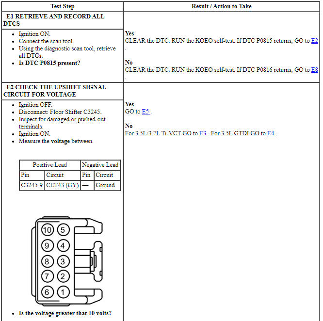
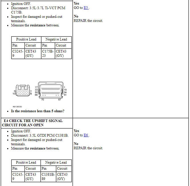
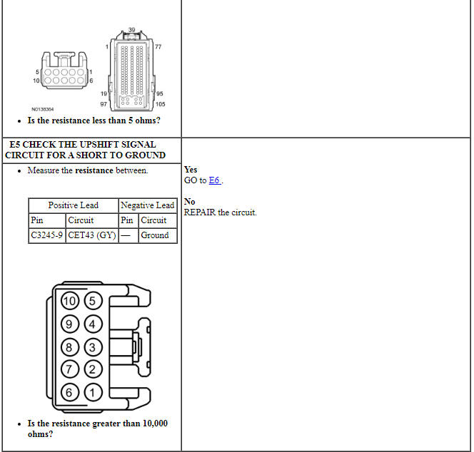
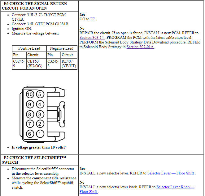
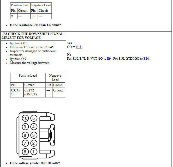
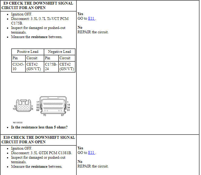
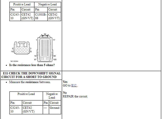
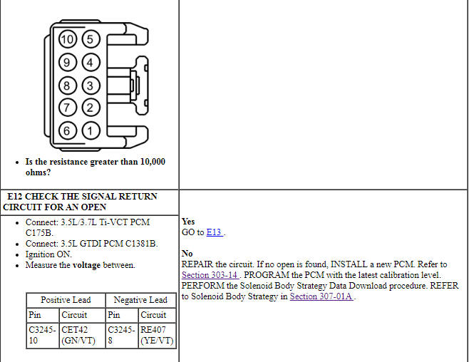
PINPOINT TEST E: P0815, P0816 (FLOOR SHIFT)
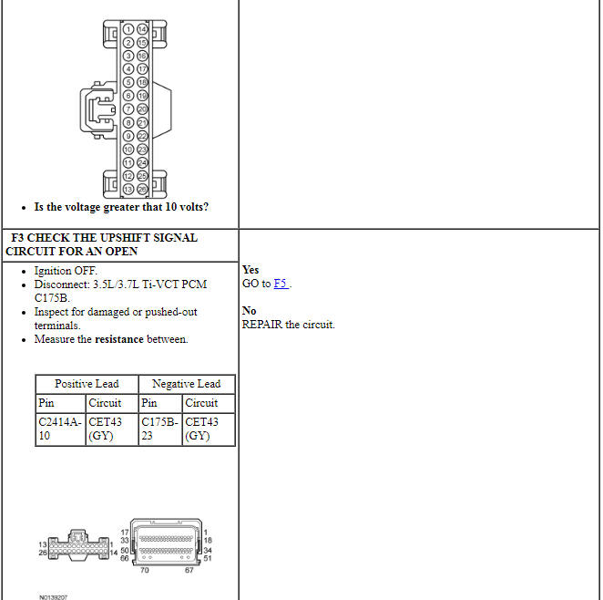
Pinpoint Test F: P0815, P0816 (Paddle Shift)
Diagnostic Overview
Diagnostics in this manual assume a certain skill level and knowledge of Ford-specific diagnostic practices. Refer to Diagnostic Methods in Section 100-00 for information about these practices.
Refer to Wiring Diagrams Cell 29 , Transmission Controls - 6 Speed for schematic and connector information.
Normal Operation and Fault Conditions
The paddle shift switch is a toggle switch integral to the steering column. When the selector lever is placed in the manual shift position, the upshift/downshift feature becomes activated and allows the operator to upshift or downshift without removing there hands from the steering wheel. If a new switch is required install a new paddle shift assembly.
DTC Fault Trigger Conditions
-
Possible Sources
- Connectors damaged or pushed-out terminals, corrosion, loose wires and missing or damaged seals.
- Paddle shift switch
- PCM
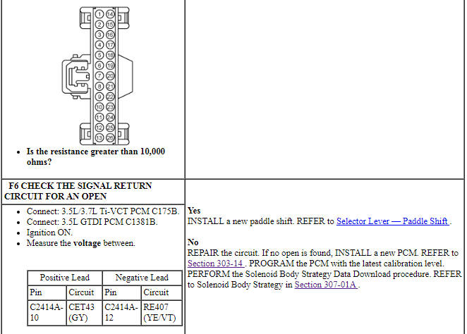
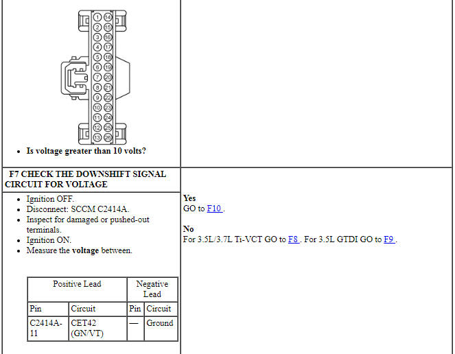
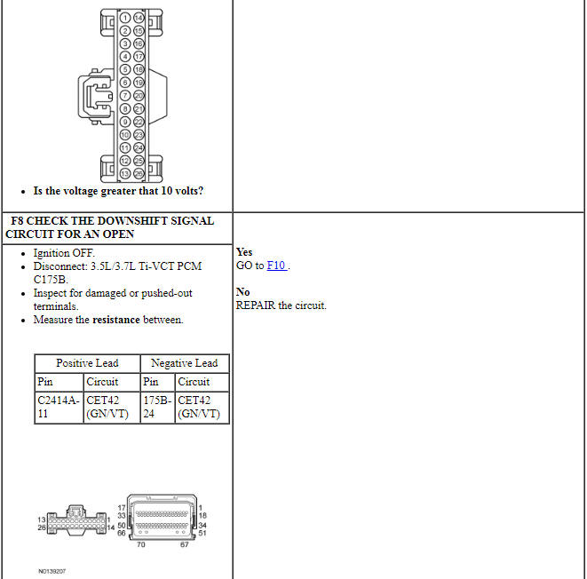
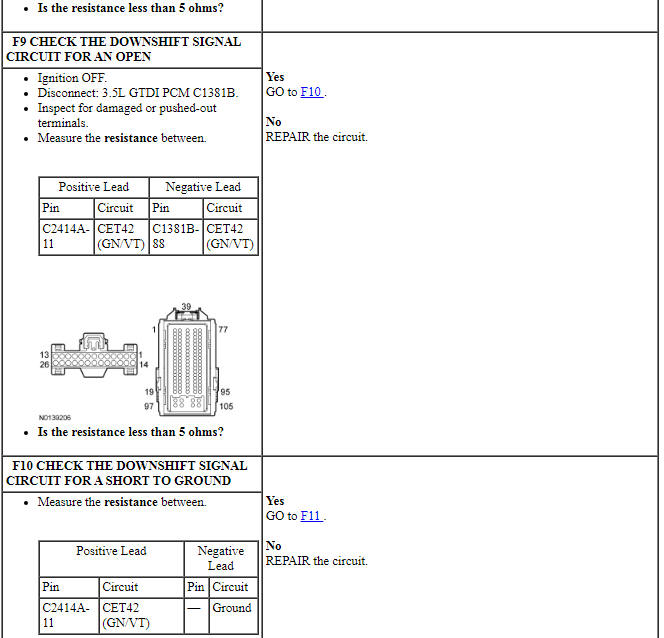
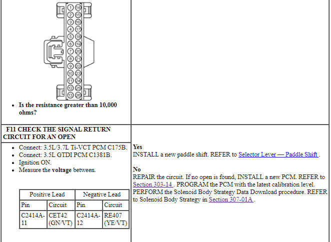
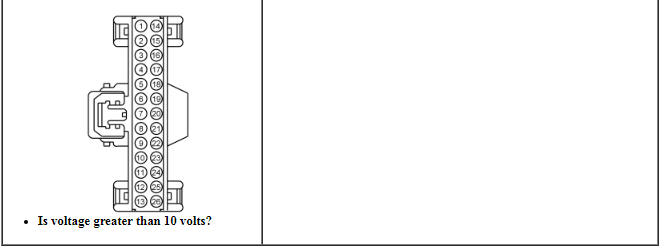
PINPOINT TEST F: P0815, P0816 (PADDLE SHIFT)

Pinpoint Test G: P1780
Diagnostic Overview
Diagnostics in this manual assume a certain skill level and knowledge of Ford-specific diagnostic practices. Refer to Diagnostic Methods in Section 100-00 for information about these practices.
Refer to Wiring Diagrams Cell 30 , Transmission Controls - 6F35 for schematic and connector information.
Normal Operation and Fault Conditions
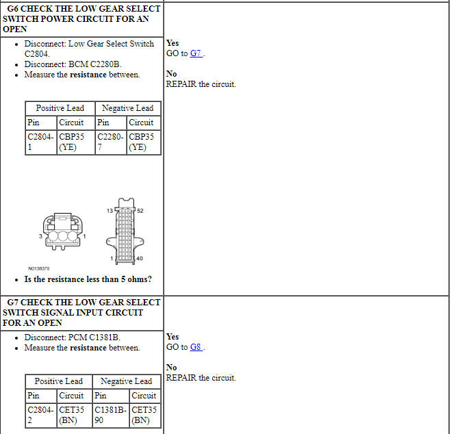
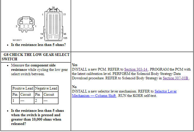
The low gear select switch is a momentary contact switch located on the end of the selector lever. Pressing the low gear select switch will allow for low (1st gear) operation or cancel low gear operation. There are no continuous DTCs for the low gear select switch but if the switch fails while the vehicle is being driven, the symptoms is, transmission shifts to low when not selected or transmission will not go into low when selected. This will depend on how and when the switch fails.
DTC Fault Trigger Conditions
 Specifications, Description and Operation
SPECIFICATIONS
Torque Specifications
DESCRIPTION AND OPERATION
External Controls
The transmission selector lever linkage consists of:
a selector lever cable that connects the transmission manual ...
 General Procedures
Brake Shift Interlock Override - Floor Shift
NOTE: If it is necessary to use the override procedure to move
the selector lever out of the PARK position, it is possible that a fuse has
blown.&nb ...
Other materials:
Collision warning system
WARNING: This system is designed to be a supplementary
driving aid. It is not intended to replace the driver’s attention,
and judgment, or the need to apply the brakes. This system does NOT
activate the brakes automatically. Failure to press the brake pedal to
activate the brakes may result in ...
Traction Control
PRINCIPLES OF OPERATION
The traction control system helps avoid drive wheel spin and loss of
traction.
If your vehicle begins to slide, the system applies the brakes to individual
wheels and, when needed, reduces engine power at the same time. If the
wheels spin when accelerating on slippery ...
Diagnosis and Testing
Rear View Mirrors - Exterior
DTC Chart(s)
Diagnostics in this manual assume a certain skill level and knowledge of
Ford-specific diagnostic practices. REFER to Section 100-00 for information
regarding these diagnostic practices.
DDM DTC Chart
DSM DTC Chart
Symptom Chart(s)
Di ...
