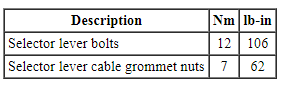
SPECIFICATIONS
Torque Specifications
DESCRIPTION AND OPERATION
External Controls
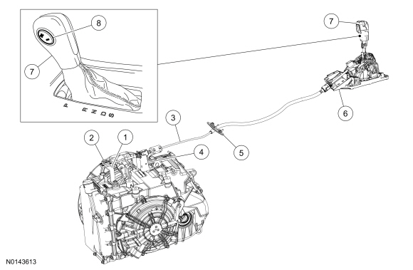
The transmission selector lever linkage consists of:
- a selector lever cable that connects the transmission manual control lever to the selector lever assembly.
- a BSIA that is integral to the selector lever assembly.
The selector lever assembly:
- locks the transmission selector lever in the PARK position when the ignition switch is in the LOCK position.
- requires the transmission selector lever to be in the PARK position to turn the ignition switch to the LOCK position.
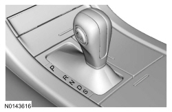
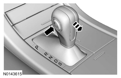
Range Selection
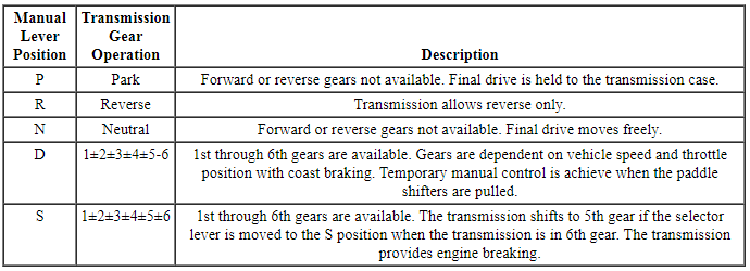
This transmission has 5 range positions: P, R, N, D and S.
Selector Lever
Park
In the PARK position:
- there is no powerflow through the transmission.
- the parking pawl locks the final drive.
- the engine may be started.
- the ignition key may be removed.
Reverse
In the REVERSE position:
- the vehicle may be operated in a rearward direction, at a reduced gear ratio.
- engine braking will occur.
Neutral
In the NEUTRAL position:
- there is no powerflow through the transmission.
- the output shaft is not held and is free to turn.
- the engine may be started.
Drive
DRIVE is the normal position for most forward driving.
In the DRIVE position:
- the transmission provides automatic shifts - 1st through 6th gears.
- the TCC is applied and released.
- temporary manual control is provided when pulling the paddles shifters. The system will determine when temporary manual control is no longer desired and reverts back to automatic control.
- the transmission provides maximum fuel economy during normal operation.
Sport
In the SPORT position:
- the transmission provides maximum engine braking.
- gears 1 through 6 are available.
- the driver can manually shift the transmission to gears 1 through 6 using the steering wheel mounted paddle shift, or the SelectShift switch on the selector lever.
- the transmission will select gears that will provide the engine braking desired, based on the vehicle inputs, this will increase engine rpm during engine braking.
SelectShift
SelectShift Switch
When the selector lever is moved to the S position, the driver can shift the transmission manually using the SelectShift switch mounted on the selector lever knob.
Paddle Shifter (SHO only)
When the selector lever is moved to the S position, the driver can shift the transmission manually using the steering wheel mounted paddle shifters.
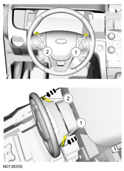
- Upshift
+ - Downshift
-
With SelectShift:
- the driver can manually shift the transmission to gears 1 through 6.
- the current gear illuminates on the IC.
- the transmission provides additional grade (engine) braking.
- the transmission will select gears that will provide the engine braking desired, based on the vehicle inputs, this will increase engine rpm during engine braking.
The transmission will make some shifts automatically primarily to protect the engine from stalling.
It is recommended to return to DRIVE mode on flat terrain to provide the best fuel economy and transmission function. The transmission returns to O/D when the selector lever is moved to the DRIVE position.
Gear Availability

 Diagnosis and Testing
External Controls
Inspection and Verification
Verify the customer concern by operating the system.
Visually inspect for obvious signs of mechanical or electrical damage.
If the concern is not ...
Other materials:
Floor mats
WARNING: Always use floor mats that are designed to fit the
foot well of your vehicle, leaving the pedal area unobstructed,
and which can be firmly secured to retention posts so that they cannot
slip out of position and interfere with the pedals or impair safe
operation of your vehicle in othe ...
Removal and Installation
Exterior Mirror
Removal and Installation
NOTE: Do not remove the exterior mirror assembly when repairing an
individual part. Individual components can be installed without removing the
exterior mirror.
Remove the sail panel.
Pull outward on the sail panel to release the retaining clips.
...
General information
Have your vehicle serviced regularly to help maintain its roadworthiness
and resale value. There is a large network of Ford authorized dealers who
are there to help you with their professional servicing expertise. We believe
that their specially trained technicians are best qualified to service y ...
