Engine
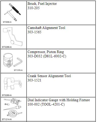
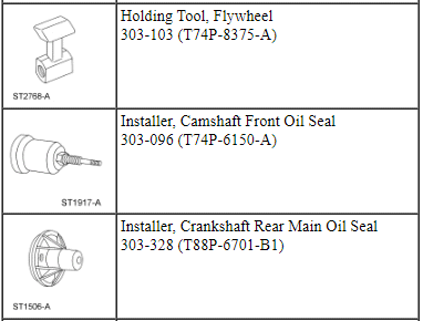
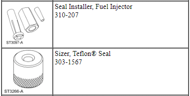
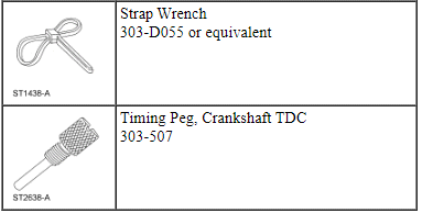
Special Tool(s)
Material

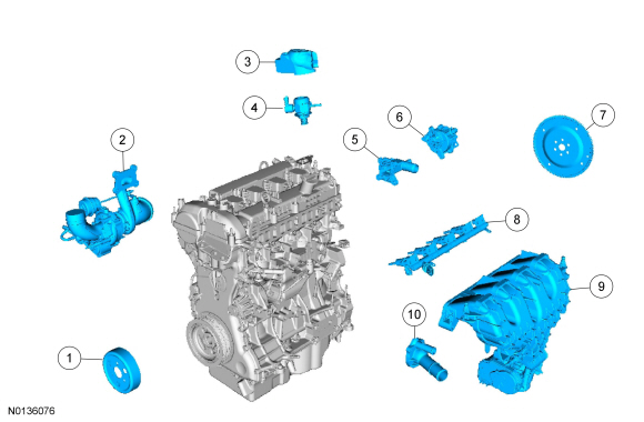
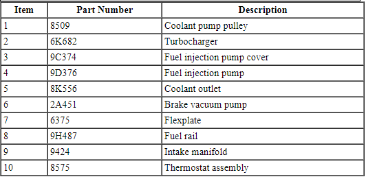
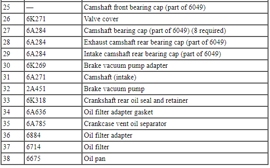
Engine - External Components
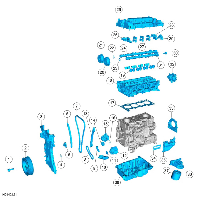
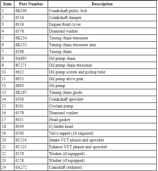
Engine - Front and Upper Components
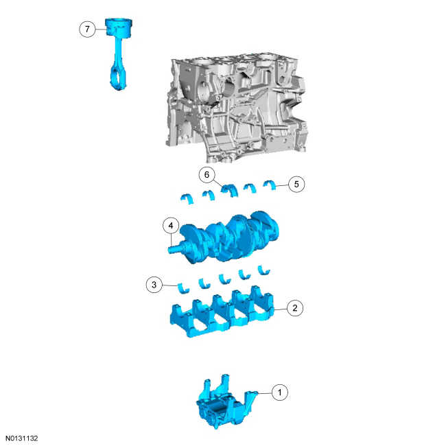
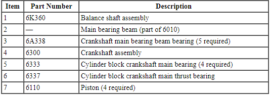
Engine - Lower Block Components
NOTICE: Do not loosen or remove the crankshaft pulley bolt without first installing the special tools as instructed in this procedure. The crankshaft pulley and the crankshaft timing sprocket are not keyed to the crankshaft. The crankshaft, the crankshaft sprocket and the pulley are fitted together by friction, using diamond washers between the flange faces on each part. For that reason, the crankshaft sprocket is also unfastened if the pulley bolt is loosened. Before any repair requiring loosening or removal of the crankshaft pulley bolt, the crankshaft and camshafts must be locked in place by the special service tools, otherwise severe engine damage can occur.
NOTICE: During engine repair procedures, cleanliness is extremely important. All parts must be thoroughly cleaned and any foreign material, including any material created while cleaning gasket surfaces, that enters the oil passages, coolant passages or the oil pan, can cause engine failure.
NOTE: Assembly of the engine requires various inspections/measurements of the engine components (engine block, crankshaft, connecting rods, pistons and piston rings). These inspections/measurements will aid in determining if the engine components will require replacement. For additional information, refer to Section 303-00.
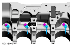
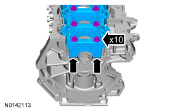
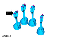
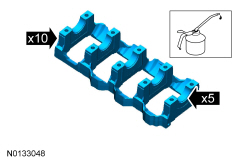
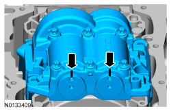
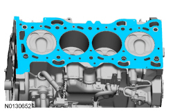
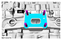
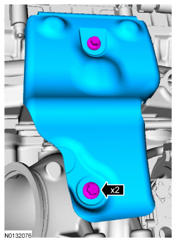
- Install the 4 engine piston oil coolers and the 4 bolts.
- Tighten to 10 Nm (89 lb-in).
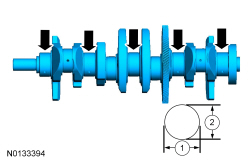
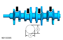
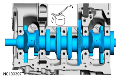
- Measure each of the crankshaft main bearing journal diameters in at least 2 directions and record the smallest diameter for each journal.
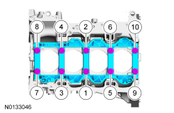
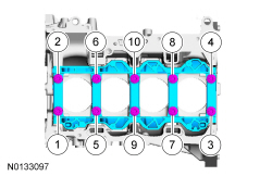
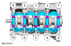
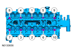
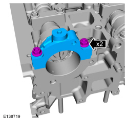
- Position the main bearing beam in the engine block with the main bearing beam mounted flush with the rear face of the engine block and install the 10 original main bearing beam bolts finger tight.
- Tighten the 10 original main bearing beam bolts in the sequence shown in
3 stages.
- Stage 1: Tighten to 5 Nm (44 lb-in).
- Stage 2: Tighten to 25 Nm (18 lb-ft).
- Stage 3: Tighten an additional 90 degrees.
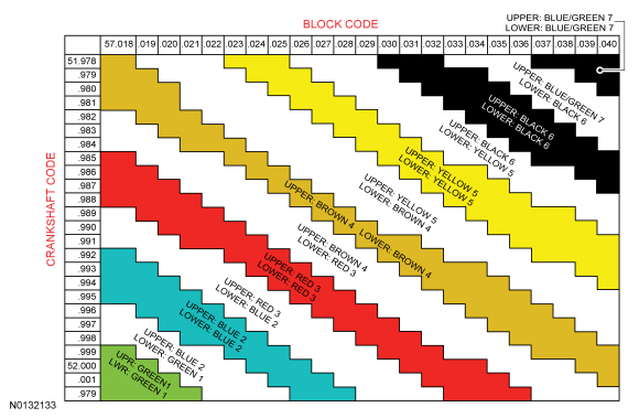
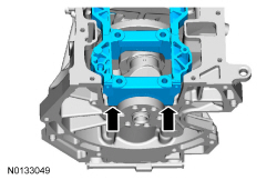
- Measure each crankshaft block main bearing bore diameter.
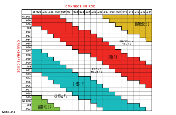
- Using the chart, select the crankshaft main bearings.
- Using the original connecting rod cap bolts, install the connecting caps
and bolts and tighten the bolts in 3 stages.
- Stage 1: Tighten to 10 Nm (89 lb-in).
- Stage 2: Tighten to 29 Nm (21 lb-ft).
- Stage 3: Tighten an additional 90 degrees.
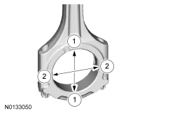
- Measure the connecting rod large end bore in 2 directions. Record the
smallest measurement for each connecting rod.
- Remove the bolts and the connecting rod cap.
- Discard the connecting rod cap bolts.
- Measure each of the crankshaft connecting rod bearing journal diameters in at least 2 directions. Record the smallest measurement for each connecting rod journal.
- NOTE: Mixed grade bearing pairs (green/blue, blue/red, red/brown)
can be installed in upper or lower positions. It is not necessary to
maintain specific position.
Using the chart, select the correct connecting rod bearings for each crankshaft connecting rod journal.
- Remove the 10 bolts in the sequence shown and the main bearing beam.
- Discard the main bearing beam bolts.
- NOTE: Before assembling the cylinder block, all sealing surfaces
must be free of chips, dirt, paint and foreign material. Also, make sure the
coolant and oil passages are clear.
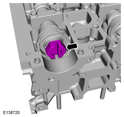
NOTE: If reusing the crankshaft main bearings, install them in their original positions and orientation as noted during disassembly.
NOTE: The center bulkhead is the thrust bearing.
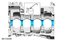
Lubricate the upper crankshaft main bearings with clean engine oil and install the 5 crankshaft main bearings in the cylinder block.
- NOTE: If reusing the crankshaft main bearings, install them in
their original positions and orientation as noted during disassembly.
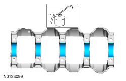
Lubricate the crankshaft main bearings with clean engine oil and install the 5 crankshaft main bearings in the main bearing beam.
- NOTE: Lubricate journals on the crankshaft with clean engine oil.
Position the crankshaft in the cylinder block.
- Lubricate the 10 main bearing beam side fit surfaces and the 5 main bearing beam bearings with clean engine oil.
- Position the main bearing beam in the engine block with the main bearing beam mounted flush with the rear face of the engine block.
- NOTE: Lubricate the main bearing beam bolt threads and under the
bolt heads with clean engine oil.
NOTE: Position the crankshaft to the rear of the cylinder block, then position the crankshaft to the front of the cylinder block before tightening the main bearing beam bolts.
Install and tighten the 10 new main bearing beam bolts in the sequence shown in 3 stages.- Stage 1: Tighten to 5 Nm (44 lb-in).
- Stage 2: Tighten to 25 Nm (18 lb-ft).
- Stage 3: Tighten an additional 90 degrees.
- Using the Dial Indicator Gauge with Holding Fixture, measure crankshaft
end play.
- Position the crankshaft to the rear of the cylinder block.
- Zero the Dial Indicator Gauge with Holding Fixture.
- Move the crankshaft to the front of the cylinder block. Note and record the crankshaft end play.
- Acceptable crankshaft end play is 0.220-0.450 mm (0.0087-0.0177 in). If the crankshaft end play exceeds the specified range, install new parts as necessary.
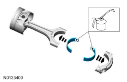
- NOTE: If reusing the connecting rod bearings, install them in
their original positions and orientation as noted during disassembly.
Install the 4 upper bearings in the connecting rods and install the 4 lower bearings into the connecting rod caps.
- Lubricate the connecting rod bearings with clean engine oil.
- NOTICE: Be sure not to scratch the cylinder wall or crankshaft
journal with the connecting rod. Push the piston down until the connecting
rod bearing seats on the crankshaft journal.
NOTE: Make sure the piston arrow on top is facing toward the front of the engine.
NOTE: Lubricate the pistons, piston rings and the entire cylinder bores with clean engine oil
Using the Piston Ring Compressor, install the 4 piston and connecting rod assemblies.- When installing the pistons and connecting rod assemblies, the oil ring gaps must be positioned 60 degrees apart from each other and a minimum of 90 degrees from the expander gap.
- The position of the upper and lower compression ring gaps are not controlled for installation.
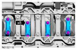
- NOTICE: The rod cap installation must keep the same
orientation as marked during disassembly or engine damage may occur.
NOTE: After installation of each connecting rod cap, rotate the crankshaft to verify smooth operation.
Install the 4 connecting rod caps and the 8 new bolts and tighten the bolts in 3 stages.- Stage 1: Tighten to 10 Nm (89 lb-in).
- Stage 2: Tighten to 29 Nm (21 lb-ft).
- Stage 3: Tighten an additional 90 degrees.
- Install the Crankshaft TDC Timing Peg and rotate the crankshaft slowly clockwise until the crankshaft balance weight is up against the TDC Timing Peg. The engine is now at TDC.

- NOTE: Due to the precision interior construction of the balance
shaft assembly, it should not be disassembled.
NOTE: The original adjustment shims must be installed in their original positions.
NOTE: Confirm by visual inspection that there is no damage to the balance shaft assembly gear and verify that the shaft turns smoothly. If there is any damage or malfunction, replace the balance shaft assembly.
Install the adjustment shims in their original positions on the seat faces of the balance shaft assembly.- With the balance shaft assembly marks in the TDC position, slowly install the balance shaft assembly onto the cylinder block to avoid interference between the crankshaft drive gear and the balance shaft assembly driven gear.
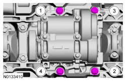
- Install the 4 balance shaft assembly bolts and tighten in the sequence
shown in 2 stages.
- Stage 1: Tighten to 25 Nm (18 lb-ft).
- Stage 2: Tighten to 42 Nm (31 lb-ft).
- Remove the Crankshaft TDC Timing Peg.
- Rotate the crankshaft to confirm that there are no meshing problems between the balance shaft assembly gear and the crankshaft gear.

- Install the Crankshaft TDC Timing Peg and rotate the crankshaft slowly
clockwise until the crankshaft balance weight is up against the TDC Timing
Peg. The engine is now at TDC.
- Remove the TDC Timing Peg.

- NOTE: Measure the backlash and verify that it is within specified
range at all of the following 6 positions: 10 degrees, 30 degrees, 100
degrees, 190 degrees, 210 degrees and 280 degrees. It will be necessary to
reset the measuring equipment between measurements.
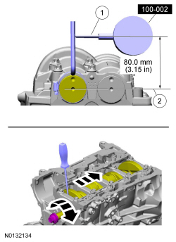
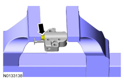
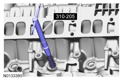
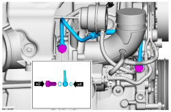
NOTE: The measurement must be taken with the Dial Indicator Gauge with Holding Fixture, a 5-mm Allen wrench and worm clamp set up as shown. Mark the Allen wrench with a file 80 mm (3.149 in) above the driven gear shaft center. Make sure the worm clamp and Allen wrench are not touching the balance shaft assembly housing.
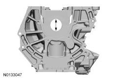
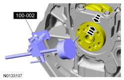
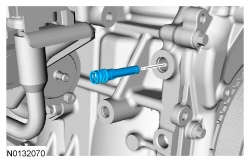
NOTE: For an accurate measurement while measuring the gear backlash, insert a screwdriver as shown into the crankshaft No. 1 crankweight area and set both the rotation and the thrust direction with the screwdriver, using a prying action as shown.
Position the Dial Indicator Gauge with Holding Fixture as shown. Measure the gear backlash.- Position the Dial Indicator Gauge with Holding Fixture (1) on the Allen wrench 80 mm (3.149 in) above the driven gear shaft center (2) on the balance shaft assembly.
- Rotate the crankshaft clockwise and measure the backlash at all of the following 6 positions: 10 degrees, 30 degrees, 100 degrees, 190 degrees, 210 degrees and 280 degrees.
- Backlash specifications are 0.020 to 0.120 mm (0.0008 to 0.0047 in).
- If the backlash exceeds the specified range, carry out the Balance Shaft Backlash procedure. For additional information, refer to Balance Shaft Backlash in this section.
- Install the Crankshaft TDC Timing Peg and rotate the crankshaft slowly clockwise until the crankshaft balance weight is up against the TDC Timing Peg. The engine is now at TDC and must remain at the TDC position until the timing drive components and crankshaft pulley are installed.
- NOTE: Clean the oil pump and cylinder block mating surfaces with
Motorcraft Metal Surface Prep.
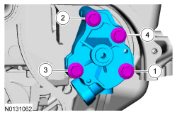
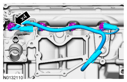
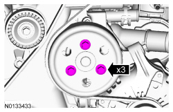
Install the oil pump assembly.
- Tighten the 4 bolts in the sequence shown in 2 stages.
- Stage 1: Tighten to 10 Nm (89 lb-in).
- Stage 2: Tighten to 20 Nm (177 lb-in).
- Tighten the 4 bolts in the sequence shown in 2 stages.
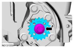
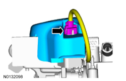
- Install the oil pump sprocket and bolt.
- Tighten to 25 Nm (18 lb-ft).
- NOTICE: Before installation, clean and inspect the diamond
washer for any damage. If damaged is evident, replace the diamond washer. If
no damage, the diamond washer is to be reused. If the diamond washer is not
installed, engine damage may occur.
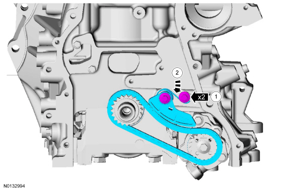
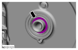
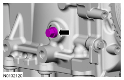
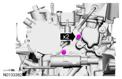
Install the diamond washer.
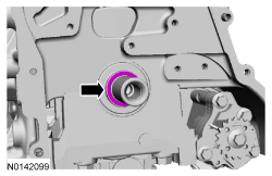
- Install the crankshaft sprocket.
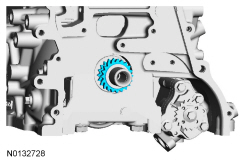
- Install the chain on the oil pump sprocket.
- Install the tensioner and the 2 shoulder bolts.
- Tighten to 10 Nm (89 lb-in).
- Push the tensioner spring down and position the spring under the shoulder bolt.
- Install the tensioner and the 2 shoulder bolts.
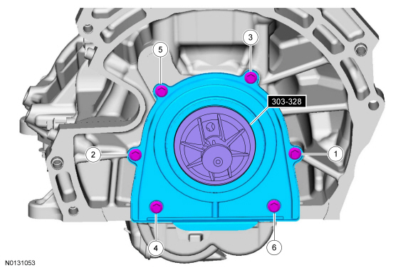
- Using the Crankshaft Rear Main Oil Seal Installer, position the
crankshaft rear oil seal with retainer plate onto the crankshaft.
- Install the 6 bolts and tighten in the sequence shown to 10 Nm (89 lb-in).
- Remove the Crankshaft Rear Main Oil Seal Installer.
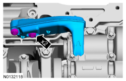
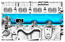
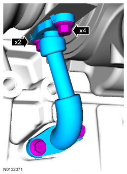
- Using a new gasket, install the oil pump screen and pickup tube and the 2 bolts.
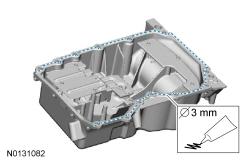
- NOTE: If the oil pan is not secured within 10 minutes of sealant
application, the sealant must be removed and the sealing area cleaned with
metal surface prep. Allow to dry until there is no sign of wetness, or 10
minutes, whichever is longer. Failure to follow this procedure can cause
future oil leakage.
Apply a 3 mm (0.118 in) bead of Silicone Gasket and Sealant to the oil pan-to-engine block mating surface.
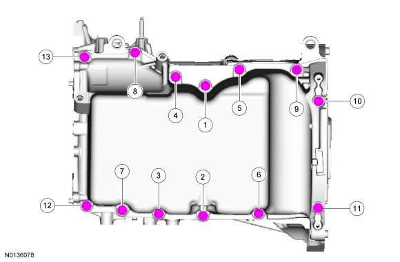
- Position the oil pan onto the engine and install the 13 bolts finger-tight.
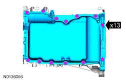
- Using a straight edge, align the front surface of the oil pan flush with the front surface of the engine block.
- Tighten in the sequence shown to 20 Nm (177 lb-in).
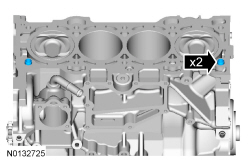
- Install the 2 cylinder head alignment dowels.
- Install a new cylinder head gasket.
- NOTE: The cylinder head bolts are torque-to-yield and must not be
reused. New cylinder head bolts must be installed.
Install the cylinder head and the 10 new bolts. Tighten the bolts in the sequence shown in 5 stages.
- Stage 1: Tighten to 7 Nm (62 lb-in).
- Stage 2: Tighten to 15 Nm (133 lb-in).
- Stage 3: Tighten to 55 Nm (41 lb-ft).
- Stage 4: Tighten 90 degrees.
- Stage 5: Tighten an additional 90 degrees.
- NOTE: Lubricate the valve tappets with clean engine oil prior to
installing.
Install the 16 valve tappets in their original positions.
- NOTE: The exhaust camshaft rear bearing cap must be secured
within 10 minutes of Gasket Maker application. If the bearing cap is not
secured within 10 minutes, the sealant must be removed and the sealing area
cleaned with Motorcraft Metal Surface Prep.
NOTE: Do not allow Gasket Maker to enter the camshaft bearing journal. If Gasket Maker is applied to the camshaft bearing journal, the journal and sealing area must be cleaned with Motorcraft Metal Surface Prep.
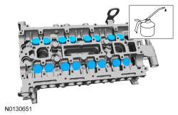
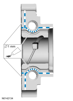
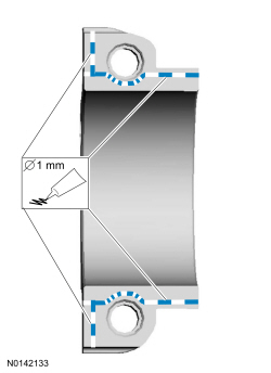
Apply 1 mm (0.039 in) beads of Gasket Maker to the exhaust rear camshaft bearing cap as shown.
- NOTICE: Install the camshafts with the alignment slots in the
camshafts lined up so the Camshaft Alignment Plate can be installed without
rotating the camshafts. Make sure the lobes on the No. 1 cylinder are in the
same position as noted in the removal procedure. Rotating the camshafts when
the timing chain is removed, or installing the camshafts 180 degrees out of
position can cause severe damage to the valves and pistons.
NOTICE: Failure to follow the camshaft tightening procedure can result in damage to the camshafts.
NOTICE: Wipe off any excess sealer from the fuel injection pump housing sealing surface of the cylinder head and rear camshaft cap.
NOTE: Lubricate the camshaft journals and camshaft bearing caps with clean engine oil.
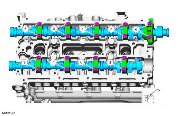
Install the camshafts and bearing caps in their original location and orientation. Tighten the camshaft bearing caps 2 turns at a time in the sequence shown in 2 stages:- Stage 1: Tighten to 7 Nm (62 lb-in).
- Stage 2: Tighten to 16 Nm (142 lb-in).
- NOTE: Lubricate the camshaft journals and the front camshaft
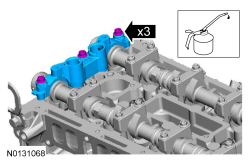
bearing cap with clean engine oil.
Install the front camshaft bearing cap and the 3 bolts. Tighten in the sequence shown in 2 stages:
- Stage 1: Tighten to 7 Nm (62 lb-in).
- Stage 2: Tighten to 16 Nm (142 lb-in).
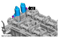
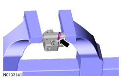
- Install the 2 VCT solenoids and the 2 bolts.
- Tighten to 10 Nm (89 lb-in).
- NOTICE: The Camshaft Alignment Tool is for camshaft alignment
only. Using this tool to prevent engine rotation can result in engine
damage.
Install the Camshaft Alignment Tool into the rear of both of the camshaft slots as shown.
- Tighten the retainer.

- NOTE: Do not tighten the camshaft phaser and sprocket bolts at
this time.
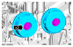
Install the intake and exhaust camshaft phaser and sprockets.
- Install the 2 bolts finger-tight.
- Install the timing chain onto the 2 camshaft phaser and sprockets and
the crankshaft sprocket.
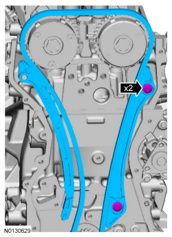
- Install the timing chain guide and the 2 bolts.
- Tighten to 10 Nm (89 lb-in).
- Install the timing chain arm.
- Install the timing chain guide and the 2 bolts.
NOTE: If the timing chain tensioner plunger and ratchet assembly are not pinned in the compressed position, follow the next 4 steps.
- NOTICE: Do not compress the ratchet assembly. This will damage
the ratchet assembly.
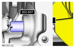
Using the edge of a vise, compress the timing chain tensioner plunger.
- Using a small pick, push back and hold the ratchet mechanism.
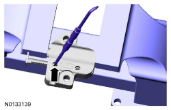
- While holding the ratchet mechanism, push the ratchet arm back into the tensioner housing.
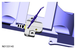
- Install a paper clip into the hole in the tensioner housing to hold the ratchet assembly and the plunger in during installation.
- Install the timing chain tensioner and the 2 bolts.
- Tighten to 10 Nm (89 lb-in).
- Remove the paper clip to release the piston.
- NOTICE: Do not rely on the Camshaft Alignment Tool to prevent
camshaft rotation. Damage to the tool or the camshaft can occur.
Using a wrench on the flats of the exhaust camshaft to prevent camshaft rotation, tighten the exhaust camshaft phaser and sprocket bolt.
- Stage 1: Tighten to 40 Nm (30 lb-ft).
- Stage 2: Tighten an additional 60 degrees.
- NOTICE: The Camshaft Alignment Tool is for camshaft alignment
only. Using this tool to prevent engine rotation can result in engine
damage.
Using a wrench on the flats of the intake camshaft to prevent camshaft rotation, tighten the intake camshaft phaser and sprocket bolt.
- Stage 1: Tighten to 40 Nm (30 lb-ft).
- Stage 2: Tighten an additional 60 degrees.
- NOTE: The engine front cover must be secured within 10 minutes of
Silicone Gasket and Sealant application. If the valve cover is not secured
within 10 minutes, the sealant must be removed and the sealing area cleaned
with Motorcraft Metal Surface Prep.
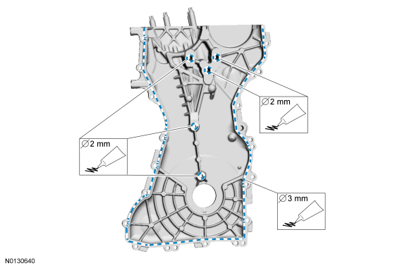
Apply a 3 mm (0.118 in) bead of Silicone Gasket and Sealant to the sealing surface of the front cover.
- Apply a 2 mm (0.078 in) bead of Silicone Gasket and Sealant to the 5 center sealing surfaces of the front cover.
- NOTE: The engine front cover must be secured within 10 minutes of
Silicone Gasket and Sealant application. If the valve cover is not secured
within 10 minutes, the sealant must be removed and the sealing area cleaned
with Motorcraft Metal Surface Prep.
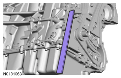
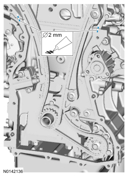
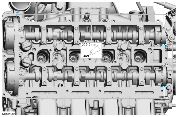
Apply beads of silicone gasket and sealant that are 2 mm (0.078 in) in diameter and 5 mm (0.19 in) in length across the cylinder head and cylinder block joint areas.
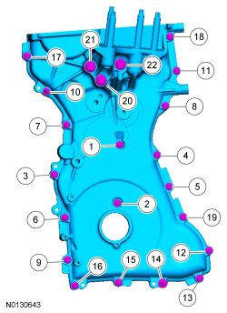
- Install the engine front cover, the 20 bolts and 2 stud bolts.
- Tighten in the sequence shown as follows:
- Tighten 1 through 19 to 10 Nm (89 lb-in).
- Tighten 20 through 22 to 48 Nm (35 lb-ft).
- Tighten in the sequence shown as follows:
- NOTE: Remove the through-bolt from the Camshaft Front Oil Seal
Installer.
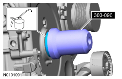
NOTE: Lubricate the oil seal with clean engine oil.
Using the Camshaft Front Oil Seal Installer, install the crankshaft front oil seal.
- NOTICE: Before installation, clean and inspect the diamond
washer for any damage. If damaged is evident, replace the diamond washer. If
no damage, the diamond washer is to be reused. If the diamond washer is not
installed, engine damage may occur.
Install the diamond washer.
- NOTE: Apply clean engine oil on the seal contact area before
installing.
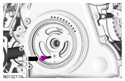
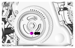
Position the crankshaft pulley onto the crankshaft and align the TDC guide hole at the 6 o'clock position.
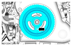
- NOTE: This step will correctly align the crankshaft pulley to the
crankshaft.
Install a standard bolt through the crankshaft pulley TDC guide hole and into the engine front cover guide hole.
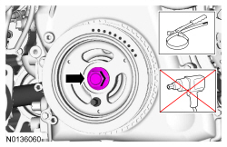
- NOTICE: The crankshaft must remain in the TDC position during
installation of the pulley bolt or damage to the engine can occur.
Therefore, the crankshaft pulley must be held in place with the Strap Wrench
and the bolt should be installed using hand tools only.
Install a new crankshaft pulley bolt. Use a Strap Wrench to hold the crankshaft pulley and tighten the crankshaft pulley bolt in 2 stages:
- Stage 1: Tighten to 100 Nm (74 lb-ft).
- Stage 2: Tighten an additional 90 degrees.
- Remove the bolt.
- NOTE: Do not tighten the CKP sensor bolts at this time.
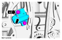
Install the CKP sensor and the 2 bolts.

- Install the Crankshaft Sensor Alignment Tool onto the CKP sensor and the
tooth of the crankshaft pulley trigger wheel.
- Tighten the 2 bolts to 7 Nm (62 lb-in).
- Remove the Crankshaft TDC Timing Peg.
- Remove the Camshaft Alignment Tool.
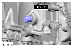
- Install the engine plug bolt.
- Tighten to 20 Nm (177 lb-in).
- Using a wrench on the flats of the intake camshaft to prevent cam
rotation, install the brake vacuum pump adapter.
- Tighten to 63 Nm (46 lb-ft).
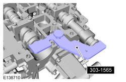
- NOTE: The intake camshaft rear bearing cap must be secured within
10 minutes of Gasket Maker application. If the bearing cap is not secured
within 10 minutes, the sealant must be removed and the sealing area cleaned
with Motorcraft Metal Surface Prep.
Apply 1 mm (0.039 in) beads of Gasket Maker to the intake rear camshaft bearing cap mating surface as shown.
- NOTICE: Wipe off any excess sealer from the vacuum pump
sealing surface of the cylinder head and camshaft cap.
Install the rear intake camshaft cap and the 2 bolts. Tighten the bolts in 2 stages:
- Stage 1: Tighten the bolts to 7 Nm (62 lb-in).
- Stage 2: Tighten the bolts to 16 Nm (142 lb-in).
- NOTE: Installation of new seals is only required if damaged seals
were removed during disassembly of the engine.
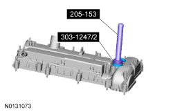
Using the VCT Spark Plug Tube Seal Installer and Handle, install new VCT solenoid seals.
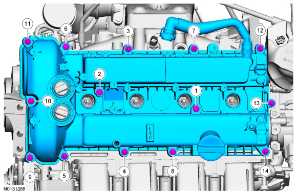
- Apply a 5.5 mm (0.216 in) drop of silicone gasket and sealant to the 6 locations shown.
- NOTE: The valve cover must be secured within 10 minutes of
silicone gasket application. If the valve cover is not secured within 10
minutes, the sealant must be removed and the sealing area cleaned with metal
surface prep.
Using a new gasket install the valve cover.
- Tighten in the sequence shown to 10 Nm (89 lb-in).
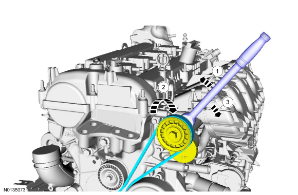
- Install the oil level indicator.
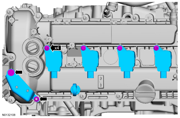
- Install the 4 coil-on-plugs and the 4 bolts.
- Tighten to 8 Nm (71 lb-in).
- Install the CAC intermediate tube mounting bracket, nut and bolt.
- Tighten to 6 Nm (53 lb-in).
- Install the 4 coil-on-plugs and the 4 bolts.
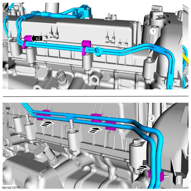
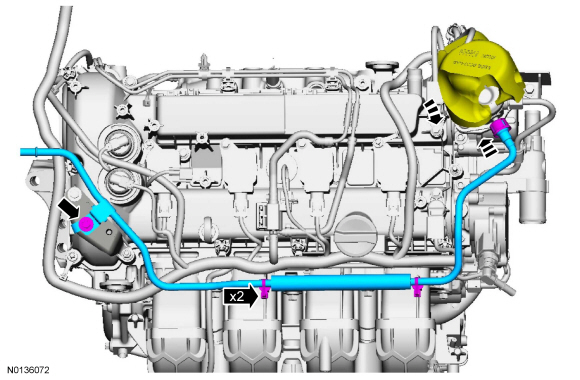
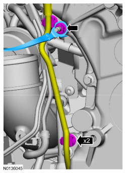
- Install the vacuum tubes.
- Early build vehicles equipped with metal vacuum tubes.
- Late build vehicles equipped with nylon vacuum tubes.
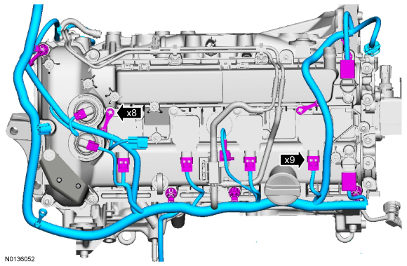
- Position the wiring harness onto the engine and attach the 8 retainers.
- Connect the 9 wiring harness electrical connectors.
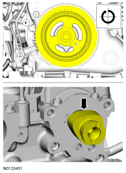
- Using the crankshaft pulley bolt, rotate the engine clockwise until the fuel injection cam lobe is at zero lift.
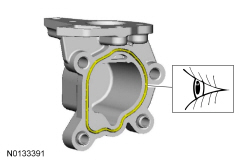
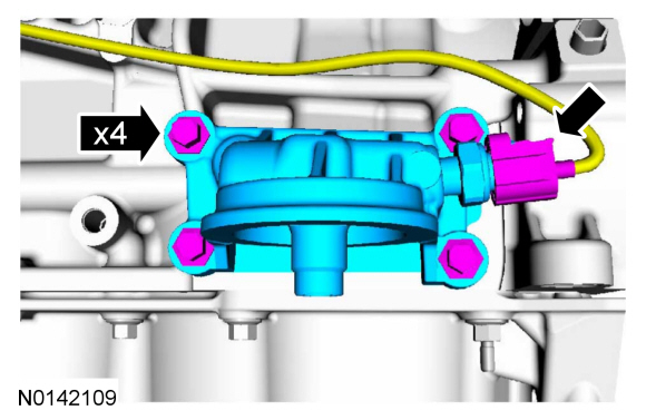
- Inspect the fuel injection pump housing gasket and replace as necessary.
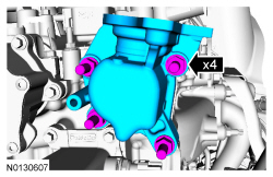
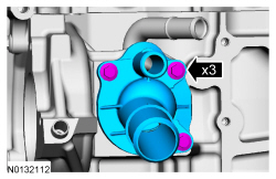
- Install the fuel injection pump housing and the 4 bolts.
- Tighten to 15 Nm (133 lb-in) plus an additional 60 degrees.
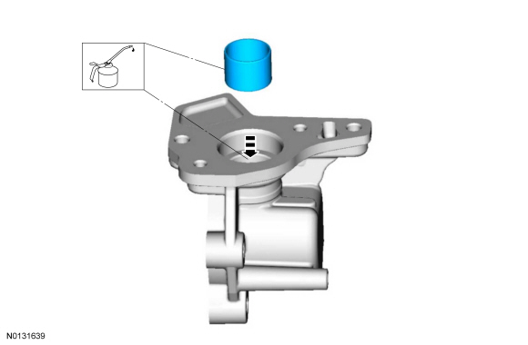
- NOTE: Apply clean engine oil to the fuel injection pump tappet
and to the fuel injection pump housing bore.
Slide the fuel injection pump tappet into the fuel injection pump housing.
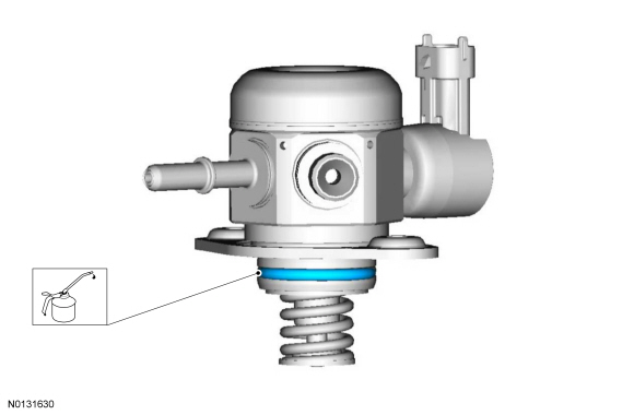
- NOTE: Make sure that a new fuel injection pump O-ring seal is
installed.
Install a new fuel injection O-ring seal.
- Lubricate the O-ring seal with clean engine oil.
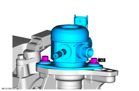
- Install the fuel injection pump and loosely install 2 fuel injection
pump bolts, alternately tighten each bolt one complete revolution until
seated. Tighten the 2 fuel injection pump bolts in the following 2 stages.
- Stage 1: Tighten each bolt to 5 Nm (44 lb-in).
- Stage 2: Tighten each bolt an additional 55 degrees.
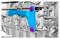
- Install the fuel injection pump bracket and the 2 bolts.
- Tighten to 17 Nm (150 lb-in).
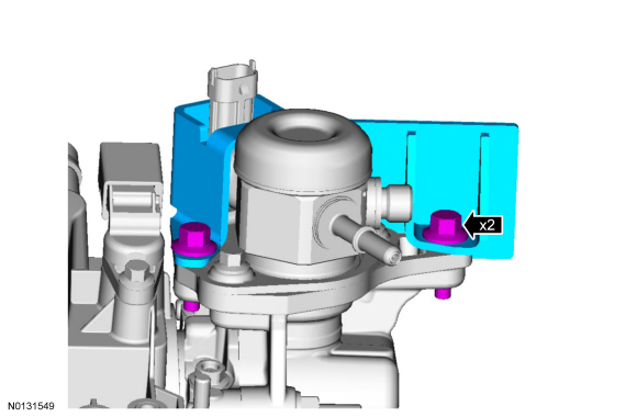
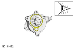
- Inspect and, if necessary, install a new brake vacuum pump gasket.
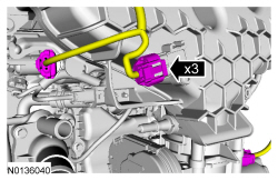
- Install the brake vacuum pump and the 3 bolts.
- Tighten to 10 Nm (89 lb-in).
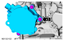
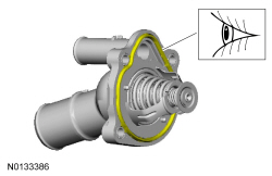
- Inspect and, if necessary, install a new thermostat housing gasket.
- Install the thermostat housing and the 3 bolts.
- Tighten to 10 Nm (89 lb-in).
- NOTICE: Do not use compressed air or the Fuel Injector Brush
to clean the tip of the fuel injectors. Failure to follow this instruction
may result in damage to the fuel injectors.
NOTE: Make sure to thoroughly clean any residual fuel or foreign material from the cylinder head, block and the general surrounding area of the fuel rails and injectors.
NOTE:
Using the Fuel Injector Brush, clean the fuel injector orifices.
- NOTE: Do not lubricate the new lower Teflon fuel injector seals.
Install new lower Teflon fuel injector seals.
- Place the Teflon Seal Sizer, knurled side out, over the fuel injector tip until the fuel injector seal recess is exposed.
- Install the new lower Teflon seal on the narrow end of the Arbor (part of the Fuel Injector Seal Installer), then install the Arbor on the fuel injector tip.
- Using the Pusher Tool (part of the Fuel Injector Seal Installer), slide the Teflon seals off of the Arbor and into the groove on the fuel injectors.

- NOTICE: Install the fuel injectors into the cylinder head
within 15 minutes due to Teflon seal expansion.
NOTE: Make sure the Teflon seal is fully seated in the groove on the fuel injector before sizing the seal.
Slide the Teflon Seal Sizer down over the Teflon seal.
- NOTICE: Use fuel injector O-ring seals that are made of
special fuel-resistant material. The use of ordinary O-ring seals may cause
the fuel system to leak. Do not reuse the O-ring seals.
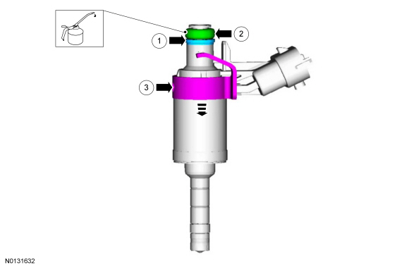
Assemble the fuel injectors.
- Install the upper fuel injector O-ring seal support ring
- Install a new upper fuel injector O-ring seal.
- Lubricate the O-ring seal with clean engine oil.
- Install a new fuel injector retainer clip
- NOTE: The anti-rotation finger of the fuel injector clip must
slip into the groove of the fuel rail cup.
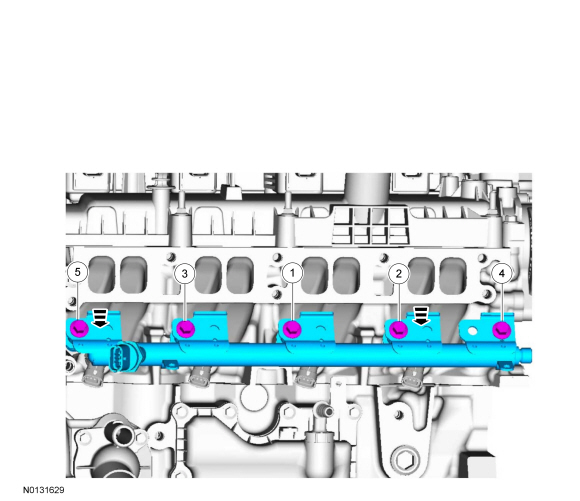
Install the fuel injectors into the fuel rail.
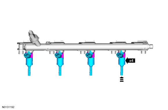
- Position the fuel rail and fuel injectors into the cylinder head and
push down on the fuel rail face above the injectors.
- Install 5 new bolts and tighten in the sequence shown in 2 stages.
- Stage 1: Tighten to 8 Nm (71 lb-in).
- Stage 2: Tighten an additional 26 degrees.
- Install 5 new bolts and tighten in the sequence shown in 2 stages.
- Install a new high pressure fuel tube and hand tighten the 2 flare nuts.
- Loosely install the 2 high pressure fuel tube bracket bolts.

- Tighten the 2 high pressure fuel tube flare nuts in 2 stages.
- Stage 1: Tighten to 15 Nm (133 lb-in).
- Stage 2: Tighten an additional 30 degrees.
- Tighten the 2 high pressure fuel tube bracket bolts to 10 Nm (89 lb-in).
- Install the fuel injection pump insulator.
- Connect the fuel injection pump electrical connector.
- Install the fuel rail insulator and the 2 pin-type retainers.
- Install the fuel charge wiring harness and connect the 4 fuel injector electrical connectors.
- Inspect and, if necessary, install a crankcase vent oil separator gasket.
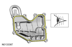
- Install the coolant bypass hose and the 2 clamps.
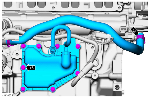
- Install the crankcase vent oil separator and the 8 bolts.
- Tighten to 10 Nm (89 lb-in).
- Install the crankcase vent oil separator and the 8 bolts.
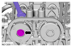
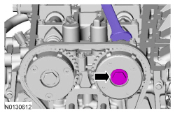
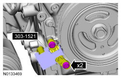
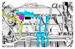
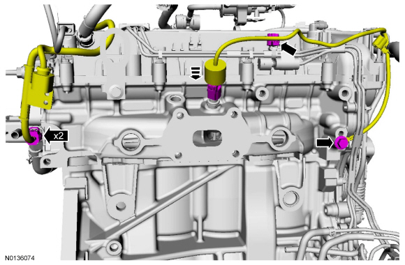
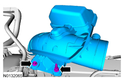
- NOTICE: The forward KS must be installed in the 6 o'clock
position and the rearward KS must be installed in the 3 o'clock position as
shown in the graphic. Failure to follow these instructions may result in
damage to the engine.
Install the 2 KS and the 2 bolts.
- Tighten to 20 Nm (177 lb-in).
- Connect the 2 KS electrical connectors.
- Attach the 2 wiring harness retainers.
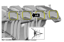
- NOTICE: If the engine is repaired or replaced because of upper
engine failure, typically including valve or piston damage, check the intake
manifold for metal debris. If metal debris is found, install a new intake
manifold. Failure to follow these instructions can result in engine damage.
Visually inspect the intake manifold gaskets for nicks, cuts and abrasions. If these conditions are not present, the gaskets may be re-used.
- Position the intake manifold and attach the 2 KS wiring harness
retainers to the intake manifold.
- Connect the TB electrical connector and attach the wiring harness retainer to the TB.
- Connect the PCV hose.
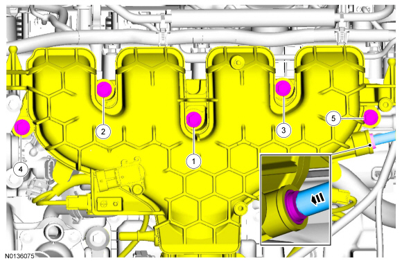
- Install the intake manifold and the 5 bolts.
- Tighten in the sequence shown to 18 Nm (159 lb-in).
- Install the vacuum tube into the quick connect coupling.
- Connect the 2 brake vacuum tube quick connect couplings. For additional information, refer to Section 310-00.
- Connect the MAP sensor, the FRP sensor and fuel charge harness electrical connectors.
- Connect the fuel supply tube to the fuel injection pump. For additional
information, refer to the quick connect coupling procedure in Section
310-00.
- Attach the 2 fuel tube retainers to the intake manifold.
- Install the fuel jumper tube bolt.
- Tighten to 8 Nm (71 lb-in).
- Install the EVAP canister purge valve and tube assembly.
- Connect the EVAP canister purge valve electrical connector.
- Connect the EVAP tube quick connect coupling. For additional
information, refer to the quick connect coupling procedure in Section
310-00.
- Attach the 2 EVAP tube retainers.
- Using a new gasket, install the oil filter adapter and the 4 bolts.
- Tighten to 25 Nm (18 lb-ft).
- Connect the EOP switch electrical connector.
- Install the CAC outlet tube and clamp.
- Tighten to 5 Nm (44 lb-in).
- Connect the EVAP tube quick connect coupling. For additional information, refer to the quick connect coupling procedure in Section 310-00.
- Install the heater hose and clamp.
- Attach the heater hose retainer to the intake manifold.
- NOTE: Lubricate the coolant pump O-ring seal with clean engine
coolant prior to installation.
Using a new O-ring seal, install the coolant pump and the 3 bolts.
- Tighten to 10 Nm (89 lb-in).
- Install the A/C compressor bracket, the bolt and the nut.
- Tighten to 25 Nm (18 lb-ft).
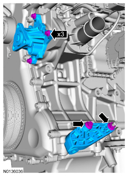
- Install the coolant pump pulley and the 3 bolts.
- Install the accessory drive belt tensioner and the 3 bolts.
- Tighten to 25 Nm (18 lb-in).
- Install the generator, the bolt and 2 stud bolts.
- Tighten to 25 Nm (18 lb-in).
- Install the accessory drive belt tensioner and the 3 bolts.
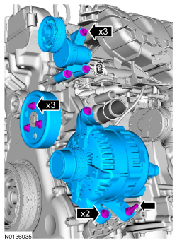
- Install the accessory drive belt.
- Tighten the 3 coolant pump pulley bolts to 20 Nm (177 lb-in).
- Install the RH halfshaft bracket and the 2 bolts.
- Tighten to 25 Nm (18 lb-in).
- Connect the CHT sensor electrical connector and slide the insulator
down.
- Attach the wiring harness retainer.
- Connect the ECT sensor electrical connector.
- Install the ground wire and bolt.
- Tighten to 20 Nm (177 lb-in).
- Install 4 new turbocharger-to-cylinder head studs.
- Tighten to 17 Nm (150 lb-in).
- Install a new turbocharger gasket.
- Install the turbocharger and 4 new nuts.
- Tighten in the sequence shown to 50 Nm (37 lb-ft).

- Install the turbocharger heat shield and the 2 bolts.
- Tighten to 10 Nm (89 lb-in).
- NOTE: Do not reuse the turbocharger oil return tube/gaskets, new
parts must be installed.
Using 2 new gaskets, install a new turbocharger oil return tube and the 4 bolts.
- Tighten to 10 Nm (89 lb-in).
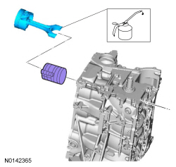
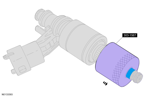
- Install a new turbocharger oil filter.
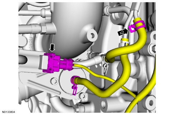
- NOTE: Do not reuse the turbocharger oil supply tube/gaskets, new
parts must be installed.
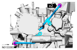
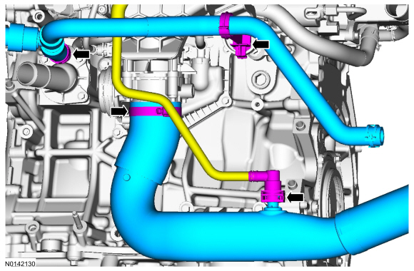
Using 4 new gaskets, install a new turbocharger oil supply tube and the 2 banjo bolts.
- Tighten to 25 Nm (18 lb-ft).
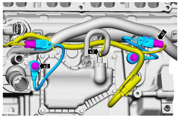
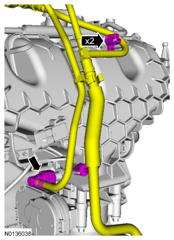
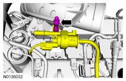
- NOTE: Early build engine with metal vacuum tubes shown, late
build engines with nylon vacuum tubes similar.
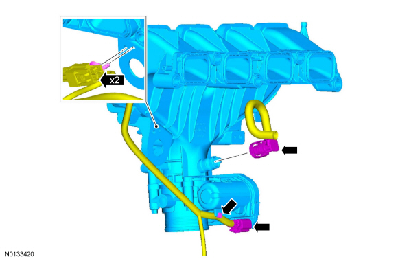
Connect the 2 turbocharger control vacuum hoses and the electrical connector.
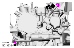
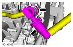
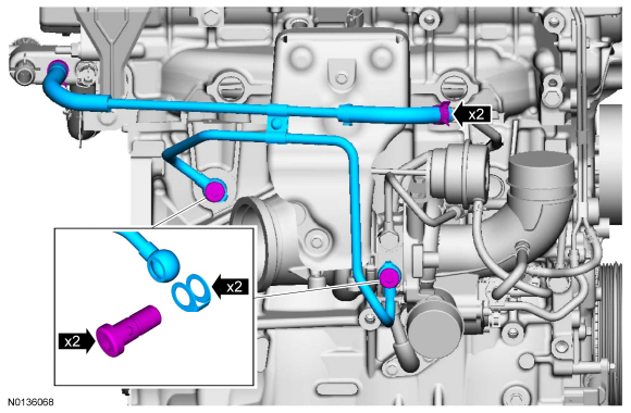
- Using 2 new gaskets, install the turbocharger coolant tube and the 2
banjo bolts.
- Tighten to 28 Nm (21 lb-ft).
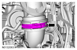
- Connect the turbocharger coolant tube and the 2 clamps.
- Install the turbocharger inlet tube, bolt and the stud bolt.
- Tighten to 5 Nm (44 lb-in).
- Connect the CKP sensor electrical connector.
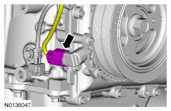
- Attach the 2 wiring harness retainers.
- Install the ground strap and nut.
- Tighten to 9 Nm (80 lb-in).
- Install the ground strap and nut.
- Position the EVAP canister purge valve and install the engine appearance
cover mounting stud.
- Tighten to 5 Nm (44 lb-in).
- Tighten the turbocharger inlet tube clamp to 5 Nm (44 lb-in).
- Install the turbocharger outlet tube and the 2 bolts.
- Tighten to 6 Nm (53 lb-in).
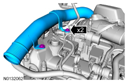
- Tighten the turbocharger outlet tube clamp to 5 Nm (44 lb-in).
- Remove the engine from the Engine Stand.
- NOTE: Special bolts are used for installation. Do not use
standard bolts.
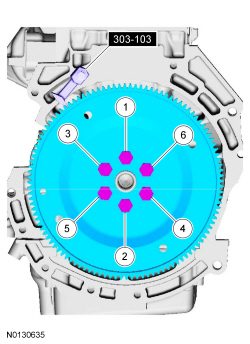
Install the flexplate, the 6 new bolts and the Flywheel Holding Tool.
- Tighten in the sequence shown in 3 stages:
- Stage 1: Tighten to 50 Nm (37 lb-ft).
- Stage 2: Tighten to 80 Nm (50 lb-ft).
- Stage 3: Tighten to 112 Nm (83 lb-ft).
- Tighten in the sequence shown in 3 stages:
 Disassembly and Assembly of Subassemblies
Cylinder Head
Special Tool(s)
Material
Disassembly
NOTICE: During engine repair procedures, cleanliness is extremely
important. Any foreign material, including any material created while cl ...
 Installation
Engine
Special Tool(s)
Material
Lubricate the torque converter pilot hub with Multi-Purpose Grease.
Remove the Torque Converter Retainer and bolt.
NOTE: Align the torque converte ...
Other materials:
Exterior Trim and Ornamentation
SPECIFICATIONS
Torque Specifications
REMOVAL AND INSTALLATION
Applique - Luggage Compartment Lid
Removal and Installation
NOTE: Removal steps in this procedure may contain installation
details.
To install, tighten to 5 Nm (44 lb-in).
If equipped.
To ...
Satellite radio information
Satellite Radio Channels
Sirius broadcasts a variety of music, news, sports, weather, traffic and
entertainment satellite radio channels. For more information and a
complete list of Sirius satellite radio channels, visit www.siriusxm.com in
the United States, www.sirius.ca in Canada, or call Sir ...
Auxiliary input jack
WARNING: Driving while distracted can result in loss of vehicle
control, crash and injury. We strongly recommend that you use
extreme caution when using any device that may take your focus off
the road. Your primary responsibility is the safe operation of your
vehicle. We recommend against the u ...
