SPECIFICATIONS
Material
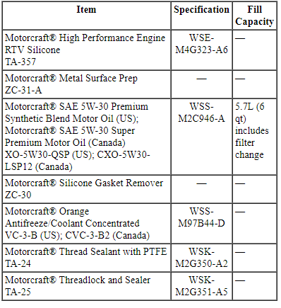
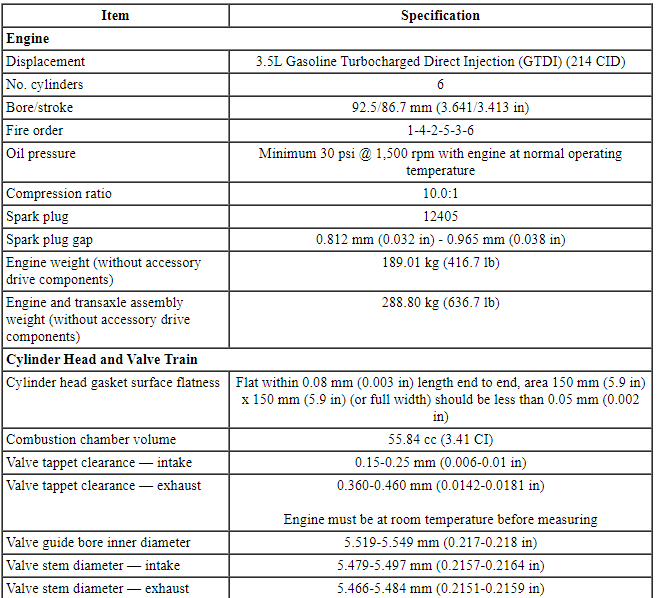
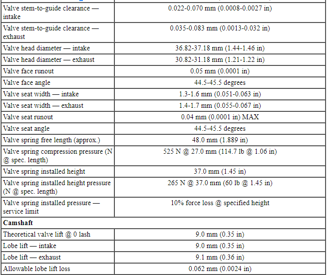
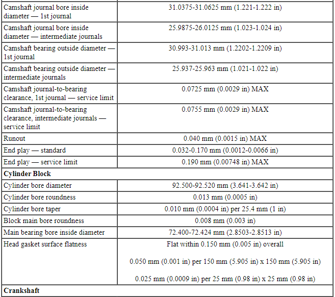
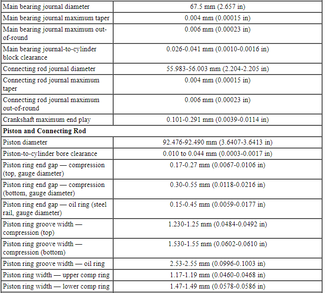
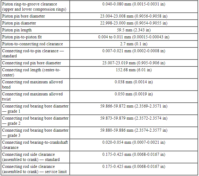
General Specifications
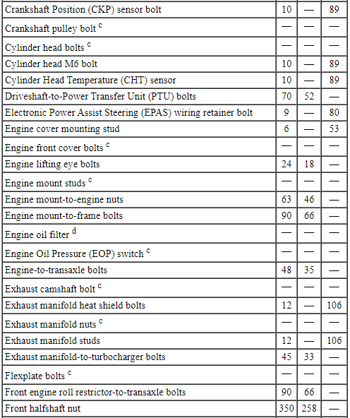
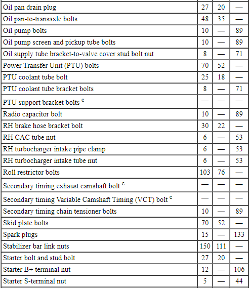
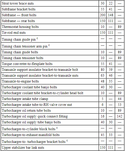
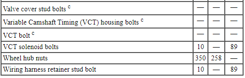
Torque Specifications
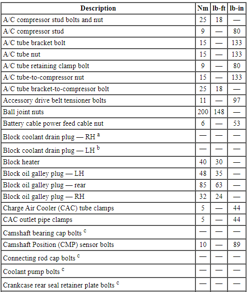
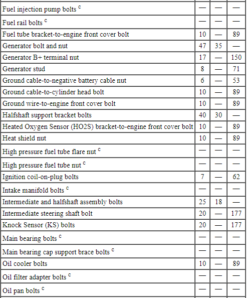
a Tighten to 10 Nm (89 lb-in) plus an additional 720 degrees.
b Tighten to 16 Nm (142 lb-in) plus an additional 180 degrees.
c Refer to the procedure in this section.
d Tighten to 5 Nm (44 lb-in) plus an additional 180 degrees.
DESCRIPTION AND OPERATION
Engine
The 3.5L Gasoline Turbocharged Direct Injection (GTDI) (4V) is a V-6 engine with the following features:
- Dual overhead camshafts
- Four valves per cylinder
- GTDI
- An aluminum intake manifold
- Aluminum cylinder heads
- An aluminum, 60-degree V-cylinder block
- Timing chain driven coolant pump
- Variable Camshaft Timing (VCT) system
- The electronic ignition system with 6 ignition coils
Engine Identification
For quick identification, refer to the safety certification decal.
- The decal is located on the LH front door lock face panel.
Engine Code Information Label
The engine code information label, located on the front side of the valve cover, contains the following:
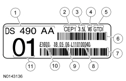
- Engine part number
- Engine plant (Cleveland)
- Engine displacement
- Engine configuration
- Duratech 3.5L GTDI
- Bar code
- Bar code
- Running number
- Engine build date (DDMMYY)
- Plant shift line
- Derivative code
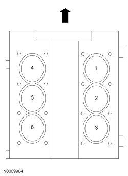
Engine Cylinder Identification
Exhaust Emission Control System
Operation and required maintenance of the exhaust emission control devices used on this engine is covered in the Powertrain Control/Emissions Diagnosis (PC/ED) manual.
Induction System
The GTDI is Pulse Width Modulated (PWM).
Fuel is metered directly into each combustion chamber. Fuel injectors pulse to follow engine firing order, in accordance with engine demand.
The various sensors detect any changes in the operating conditions and send signals to the PCM. This permits the PCM to control the opening duration (pulse width) of the fuel injectors and maintain optimum exhaust emission control and engine performance for all operating conditions.
Valve Train
The valve train uses Direct Acting Mechanical Buckets (DAMB). The camshaft lobes are positioned directly above mechanical buckets which are positioned on top of the valves.
Variable Camshaft Timing (VCT) System
The VCT system changes intake camshaft timing dependent on engine speed, load and oil temperature. Oil pressure advances and retards camshaft timing to improve low-speed and high-speed engine performance, engine idle quality and exhaust emissions.
PCV System
All engines are equipped with a closed-type PCV system recycling the crankcase vapors to the upper intake manifold.
Lubrication System
The engine lubrication system is of the force-feed type in which oil is supplied under full pressure to the crankshaft, connecting rod bearings, timing chain tensioners and VCT solenoids. The flow of oil to the valve tappets and valve train is controlled by a restricting orifice located in the cylinder head, front camshaft cap.
Oil Pump
The lubrication system is designed to provide optimum oil flow to critical components of the engine through its entire operating range.
The heart of the system is a positive displacement internal gear oil pump.
Generically, this design is known as a gerotor pump, which operates as follows:
- The oil pump is mounted on the front face of the cylinder block.
- The inner rotor is piloted on the crankshaft post and is driven through flats on the crankshaft.
- System pressure is limited by an integral, internally-vented relief valve which directs the bypassed oil back to the inlet side of the oil pump.
- Oil pump displacement has been selected to provide adequate volume to make sure of correct oil pressure both at hot idle and maximum speed.
- The relief valve calibration protects the system from excessive pressure during high-viscosity conditions.
- The relief valve is designed to provide adequate connecting rod bearing lubrication under high-temperature and high-speed conditions.
Cooling System
NOTE: During normal vehicle operation, Motorcraft Specialty Orange Engine Coolant may change color from orange to pink or light red. As long as the engine coolant is clear and uncontaminated, this color change does not indicate the engine coolant has degraded nor does it require the engine coolant to be drained, the system to be flushed, or the engine coolant to be replaced.
The engine cooling system includes the following:
- Radiator
- Timing chain driven coolant pump
- Electric fan assembly(s)
- Degas bottle (aids in maintaining the correct volume of engine coolant)
- Coolant thermostat
- Coolant hoses
DIAGNOSIS AND TESTING
Engine
For basic engine mechanical concerns, refer to Section 303-00. For driveability concerns, refer to the Powertrain Control/Emissions Diagnosis (PC/ED) manual.
GENERAL PROCEDURES
Valve Clearance Check
- Remove the valve covers. For additional information, refer to Valve Cover - LH and Valve Cover - RH in this section.
- NOTE: Engine must be at room temperature before measuring. The
valve clearance must be measured with the camshaft at base circle. The
engine will have to be rotated with the crankshaft pulley bolt to bring each
valve to base circle.
Use a feeler gauge to measure the clearance of each valve and record its location. A midrange clearance is the most desirable:
- Intake: 0.15-0.25 mm (0.006-0.01 in)
- Exhaust: 0.360-0.460 mm (0.0142-0.0181 in)
- NOTE: The number on the valve tappet reflects the thickness of
the valve tappet. For example, a tappet with the number 3.310 has the
thickness of 3.31 mm (0.13 in).
If any of the valve clearances are out of specification, select new tappets using this formula: tappet thickness = measured clearance + the base tappet thickness - most desirable thickness.
Select the tappets and mark the installation location.
- If required, install the new selected valve tappets in the marked locations. For additional information, refer to Valve Tappets in this section.

 In-Vehicle Repair
Intake Manifold
Removal
NOTICE: During engine repair procedures, cleanliness is extremely
important. Any foreign material, including any material created while cleaning
gasket surfaces that ent ...
Other materials:
SecuriLock® passive anti-theft system
Note: The system is not compatible with non-Ford aftermarket remote
start systems. Use of these systems may result in vehicle starting
problems and a loss of security protection.
Note: Metallic objects, electronic devices or a second coded key on the
same key chain may cause vehicle starting i ...
Diagnosis and Testing
Glass, Frames and Mechanisms
Special Tool(s)
DTC Charts
Diagnostics in this manual assume a certain skill level and knowledge of
Ford-specific diagnostic practices. Refer to Diagnostic Methods in Section
100-00 for information about these practices.
BCM DTC Chart
HVAC Module DTC C ...
Installation
Engine
Special Tool(s)
Material
NOTICE: Whenever turbocharger air intake system components are
removed, always cover open ports to protect from debris. It is important that no
foreign material enter the system. The turbocharger compressor vanes are
susceptible to damage from even small par ...
