SPECIFICATIONS
Material
Torque Specifications
DESCRIPTION AND OPERATION
Glass, Frames and Mechanisms
Overview
The accessory delay relay, located in the BCM, provides voltage for the operation of the power windows and the roof opening panel (if equipped). Refer to Delayed Accessory Power.
Standard power window features include:
SE, SEL
- One-touch up and one-touch down (LH front window only)
SHO, Limited
- One-touch up and one-touch down (LH and RH front windows only)
All Vehicles
The window control switch:
- can be used to manually raise or lower all windows from the master window control switch or the individual side window from the corresponding individual door switch.
- can automatically lower/raise the LH or RH front windows (SHO, Limited) when the corresponding front window control switch is momentarily pressed/pulled to the second detent position and released.
- has a passenger rear window lock-out feature.
Rear Window Defrost
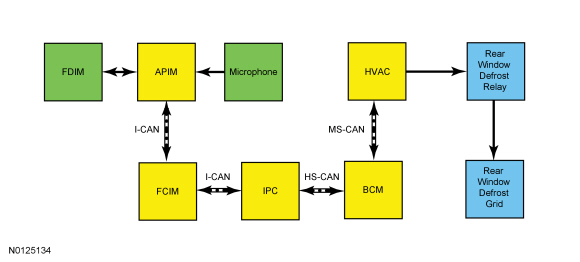
The HVAC module controls the rear window defrost relay (located in the BJB ). The HVAC module activates the rear window defrost relay when the rear window defrost switch (integral to the FCIM ) is pressed. If equipped, the rear window defrost can also be activated/deactivated by using a touchscreen interface or voice commands. When the rear window defrost relay is active, the rear window defrost grid is energized.
System Operation
System Diagram - Rear Window Defrost
Network Message Chart - Rear Window Defrost
Module Network Input Messages - FCIM
Module Network Input Messages - HVAC
Rear Window Defrost
When the rear window defrost switch (integral to the FCIM ) is pressed and the engine is running, the HVAC module activates the rear window defrost relay located in the BJB. When the rear window defrost relay is active, the rear window defrost grid is energized.
If equipped, the rear window defrost can also be commanded on and off using voice commands or by touching the rear window defrost button located on the touchscreen interface ( FDIM ). For additional information on voice or touchscreen commanded features, refer to the Owner's Literature.
The HVAC module deactivates the rear window defrost relay when one of these conditions is met:
- The rear window defrost switch is pressed when the feature is active.
- If equipped, the rear window defrost is commanded off using voice command or the touchscreen interface when the feature is active.
- Ignition state is changed from RUN to OFF.
- The 15-minute timer completes.
Remote Start - Rear Window Defrost Operation
The customer can select different climate control modes/preferences when the vehicle is started using the remote start feature. This can be accessed through the message center. For additional information on setting the remote start preferences, refer to the Owner's Literature. When the rear defrost is set to AUTO mode, the rear window defrost activates when the outside temperature is less than 0Âş C (32Âş F) and the vehicle is started using the remote start feature. No climate control adjustments are recognized during remote start operation. Once the ignition is cycled to the ON position, the climate control system returns to the previous settings (last ignition ON cycle) and adjustments can be made normally. If the previous setting was off, the climate control system turns off.
Delayed Accessory Power
The BCM controls voltage to the power windows, the audio system and the power roof opening panel (if equipped) with the accessory delay relay. The BCM activates the accessory delay relay whenever the ignition is in the RUN or the ACC position, or when the ignition is changed from RUN or ACC to the OFF position and the LH and RH front doors are closed.
The BCM deactivates the accessory delay relay when:
- the LH or RH front door is ajar and the ignition is in the OFF or key-out position.
- ten minutes have elapsed since the ignition was changed from ACC or RUN to the OFF position.
Front Power Windows
NOTE: For SHO and Limited, RH front window operation is identical to LH.
NOTE: A new LH front window motor cannot operate in one-touch up mode, and the bounce-back feature is disabled prior to initialization. If the switch is actuated to the auto UP position and released, window movement stops when the up contact in the front window control switch is released. If the front window motor is removed from the window regulator drum housing, or if a new front window motor is installed, it must be initialized. REFER to Window Motor Initialization.
The LH front window motors operate with the ignition in the RUN or ACC positions, or when the accessory delay relay is active. The high current required to move the front windows are supplied through the B+ and motor ground input.
The window control switch(es) sends 2 separate signals to the window motor: up and down. When the window control switch is pressed to the first detent position, a 12-volt signal is sent to the window motor to request an up or down operation. When auto up or auto down is requested (switch pressed to the second detent position), the window control switch provides a 12-volt signal on both the up and down line simultaneously. During an auto up or auto down request, the window motor determines intended window direction by the signal first received. If the window control switch is pressed too quickly to the second detent position (less than 5 milliseconds of time between first detent signal and second detent signal), the window motor will not be able to determine the intended direction request and will not operate until the window control switch is released and pressed again. The up and down contacts are floating within the window control switch when the switch is in the neutral position. The up and down feeds to the window motor are all low current.
When the LH front window motor is operating in auto or manual mode and the window control switch is held in the opposite direction, the glass movement will pause for a half second, then change direction.
The LH front window motors have a security override feature. If an obstacle has been detected in the window opening as the window glass is moving upward, the window motor automatically reverses direction and moves the glass toward the bounce-back position (in both manual up and one-touch up modes). Once the window motor stops the glass at its bounce-back position, and within 2 seconds the switch is released, then held in the auto UP position, the window motor moves the glass up with no bounce-back protection (security override). If the switch is released before the window glass reaches the fully CLOSED position, the window motor stops with bounce-back automatically enabled for the next window up movement. If the ignition is turned to OFF or START (without delayed accessory), the window motor stops. The only exception is when an obstacle is detected in the window opening while delayed accessory power is not present. In this case the window motor bounces back, then stops. Ice, contaminant buildup and environmentally induced tight spots in the front window seals are all possible conditions that can activate the bounce-back feature. If an obstruction occurs between 4 mm (0.15 in) and 200 mm (7.87 in) of window opening, the bounce-back position is 250 mm (9.84 in) of window opening. If an obstruction occurs at a position more than 200 mm (7.87 in) of window opening, the bounce-back position is 50 mm (1.96 in) below where the obstruction occurred.
Passenger Windows Lock-Out
When the lock-out switch (part of the master window control switch) is in the LOCK position, the rear passenger power windows only operate from the master window control switch.
Global Open - SHO and Limited only
NOTE: The global open feature may be enabled/disabled by the customer following a procedure listed in the Owner's Literature. For a complete list of available programmable parameters, refer to Section Section 418-01.
The BCM sends a signal on the global open circuit, to both front door window motors and the roof opening panel motor (if equipped), to open the windows based on a signal received from the RKE transmitter. If the accessory delay relay is active, the global open feature will not operate.
Component Description
Master Window Control Switch
The master window control switch is supplied voltage whenever the accessory delay relay is active. For additional information about the accessory delay relay, refer to Delayed Accessory Power.
- The master window control switch supplies operating voltage to both rear passenger window control switches whenever the lock-out switch is in the UNLOCK position.
- When operating any passenger power window from the master window control switch, low current voltage signals are sent to the corresponding passenger window control switch to move the window up or down.
Passenger Window Control Switch - Front
The RH front window control switch is supplied voltage whenever the accessory delay relay is active. For additional information about the accessory delay relay, refer to Delayed Accessory Power.
All vehicles
The RH window control switch contains 2 relays, which when at rest (inactive), provide a ground path to the power window motor circuit(s). When the master window control switch or RH front window control switch is activated, the corresponding relay located within the RH window control switch is energized which supplies voltage (high current) to operate the power window motor in the desired direction.
SHO, Limited
The RH window control switch contains 2 detent positions for each window switch direction. Activating the switch to the first detent position provides a voltage signal (low current circuit) to the corresponding window motor circuit for the direction desired. Activating the switch to the second detent position provides a voltage signal (low current circuit) to both (up and down) window motor circuits to operate in one-touch up/down mode. The RH power window motor interprets the desired window direction based upon which signal it receives first.
Passenger Window Control Switch - Rear
The rear window control switches receive voltage (high current circuit) from the accessory delay relay whenever it is active. For additional information about the accessory delay relay, refer to Delayed Accessory Power. The rear window control switches receive voltage (low current circuit) from the master window control switch when the lock-out switch is in the UNLOCK position. The rear window control switches each have a dedicated ground circuit.
The rear window control switches contain 2 integral relays, which when at rest (inactive), provide a ground path to their respective power window motor circuit(s).
When the master window control switch or rear window control switch is activated, the corresponding relay located within the rear window control switch is energized which supplies voltage (high current) to operate the power window motor in the desired direction.
Window Regulator Motor - Front
SE, SEL
The RH front power window motor is bi-directional. Window direction is determined by the polarity of the voltage and ground being supplied to the motor from the window control switch.
All vehicles
The LH front (and RH front, SHO and Limited) power window motor(s) contains integral electronics that control and monitor the glass movement (for obstacle detection and one-touch up/down functionality). The front power window motor inputs contain these circuits:
- Battery voltage (high current circuit to operate the motor for glass movement)
- Ignition voltage (low current circuit to power the logic of the integral electronics within the power window motor)
- Ground (circuit provides ground for motor operation as well as logic of the integral electronics within the power window motor)
- Up (low current voltage signal comes from the window control switch when activated to move the glass upward (or anytime the window control switch is placed in the second detent position) )
- Down (low current voltage signal comes from the window control switch when activated to move the glass downward (or anytime the window control switch is placed in the second detent position) )
Window Regulator Motor - Rear
The rear power window motors are bi-directional. Window direction is determined by the polarity of the voltage and ground being supplied to the motor from the window control switch.

 Diagnosis and Testing
Glass, Frames and Mechanisms
Special Tool(s)
DTC Charts
Diagnostics in this manual assume a certain skill level and knowledge of
Ford-specific diagnostic practices. Refer to Diagnostic Methods in&nb ...
Other materials:
Memory function
The memory control, located on the side seat panel, allows positioning
recall of the:
• Driver seat.
• Power mirrors.
• Adjustable pedals (if equipped).
• Power tilt/telescopic steering column (if equipped).
A. Type 1
B. Type 2
Programming a memory position
Note: You can pro ...
General Procedures
Remote Keyless Entry (RKE) Transmitter Programming
NOTE: The Remote Keyless Entry (RKE) transmitter of the Integrated
Keyhead Transmitter (IKT) is programmed automatically during the Passive
Anti-Theft System (PATS) programming. For information on programming
the IKT keys, refer to ...
Fuel Charging and Controls - 3.7L Ti-VCT
SPECIFICATIONS
Material
Torque Specifications
DESCRIPTION AND OPERATION
Fuel Charging and Controls
Component Locations
WARNING: Do
not smoke, carry lighted tobacco or have an open flame of any type when working
on or near any fuel-related component. Highly flammable mixtures are always
present ...
