
Wipers and Washers
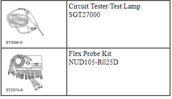
Special Tool(s)
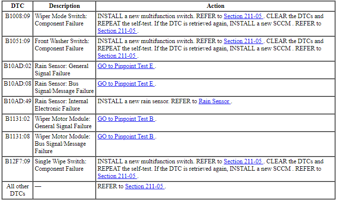
DTC Chart
Diagnostics in this manual assume a certain skill level and knowledge of Ford-specific diagnostic practices. REFER to Diagnostic Methods in Section 100-00 for information about these practices.
SCCM DTC Chart
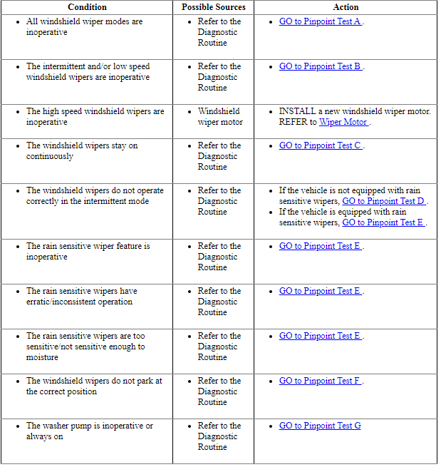
Symptom Chart
Diagnostics in this manual assume a certain skill level and knowledge of Ford-specific diagnostic practices. REFER to Diagnostic Methods in Section 100-00 for information about these practices.
Pinpoint Tests
Pinpoint Test A: All Windshield Wipers Modes Are Inoperative
Diagnostic Overview
Diagnostics in this manual assume a certain skill level and knowledge of Ford-specific diagnostic practices. REFER to Diagnostic Methods in Section 100-00 for information about these practices.
Refer to Wiring Diagrams Cell 81, Wipers and Washers for schematic and connector information.
Normal Operation and Fault Conditions
REFER to System Operation, Windshield Wipers in Wipers and Washers.
REFER to System Operation, Windshield Washer in Wipers and Washers.
REFER to Component Description, Multifunction Switch in Wipers and Washers.
REFER to Component Description, Front Wiper Motor in Wipers and Washers.
-
Possible Sources
- Fuse
- Wiring, terminals or connectors
- Wiper relay
- Multifunction switch
- Wiper motor
- SCCM
Visual Inspection and Diagnostic Pre-checks
- Inspect the BJB fuse 4 (30A) and make sure it is OK.
- Inspect the wiper relay for damage.
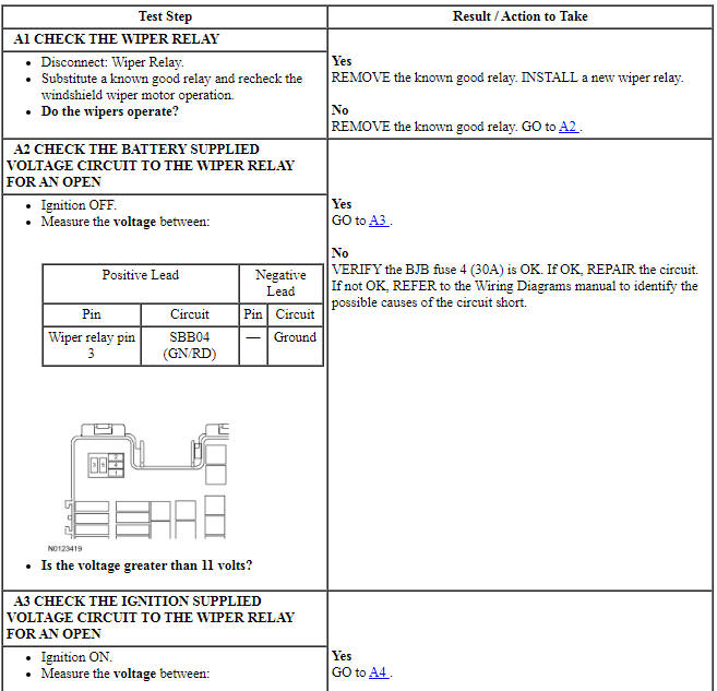
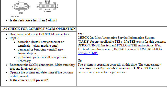
PINPOINT TEST A: ALL WINDSHIELD WIPER MODES ARE INOPERATIVE
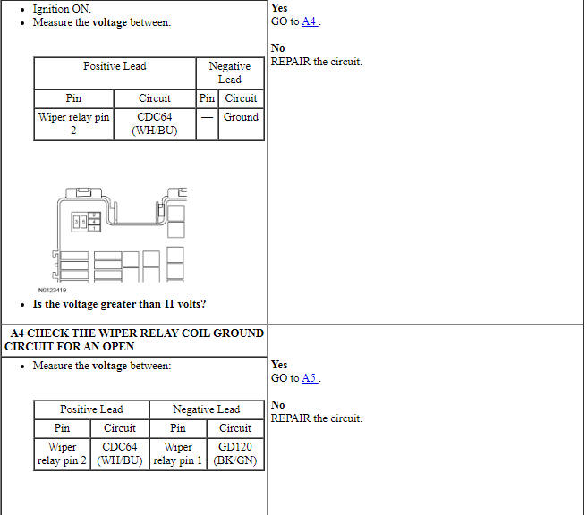
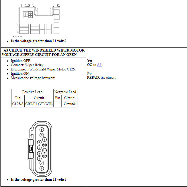
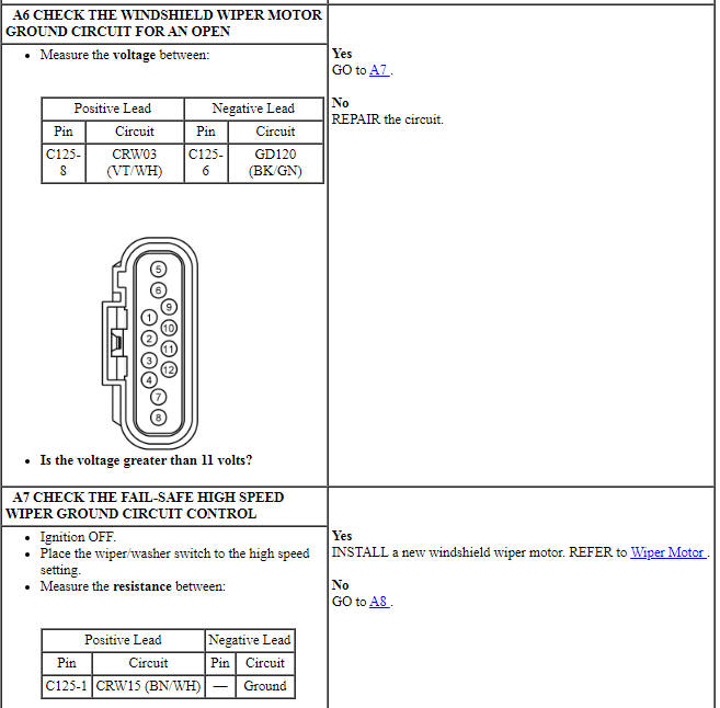
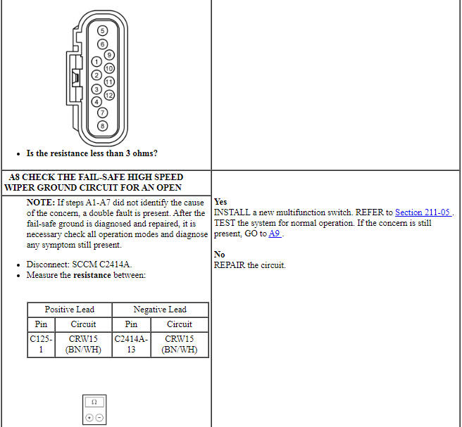
Pinpoint Test B: The Intermittent And/Or Low Speed Windshield Wipers Are Inoperative
Diagnostic Overview
Diagnostics in this manual assume a certain skill level and knowledge of Ford-specific diagnostic practices. REFER to Diagnostic Methods in Section 100-00 for information about these practices.
Refer to Wiring Diagrams Cell 81, Wipers and Washers for schematic and connector information.
Normal Operation and Fault Conditions
REFER to System Operation, Windshield Wipers in Wipers and Washers.
REFER to System Operation, Intermittent Wipers in Wipers and Washers.
REFER to Component Description, Multifunction Switch in Wipers and Washers.
REFER to Component Description, Front Wiper Motor in Wipers and Washers.
SCCM DTC Fault Trigger Conditions

-
Possible Sources
- Wiring, terminals or connectors
- Multifunction switch
- Wiper motor
- SCCM
Visual Inspection and Diagnostic Pre-checks
- Inspect the multifunction switch for damage.
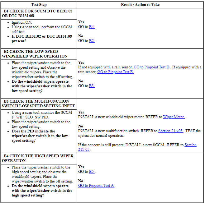
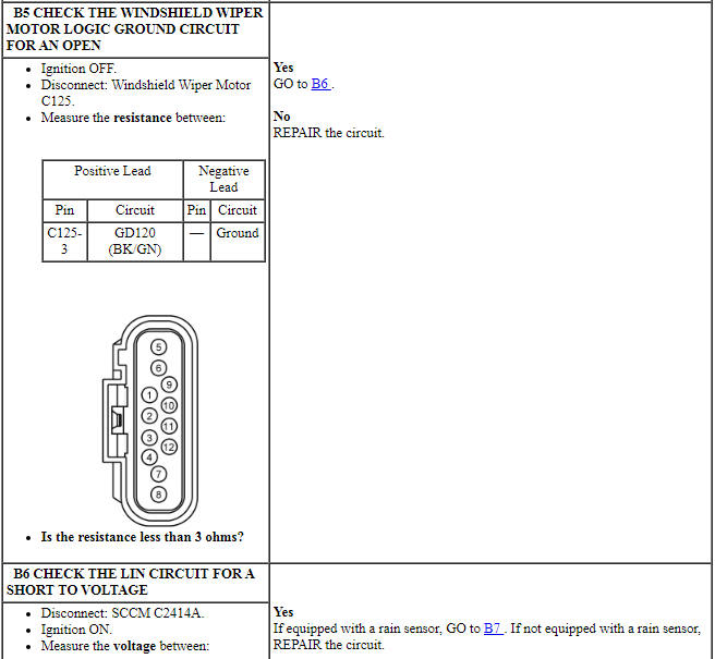
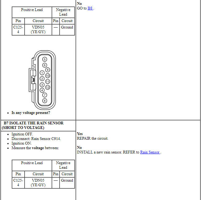
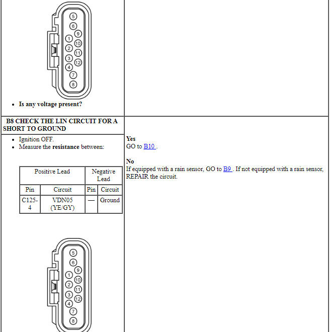
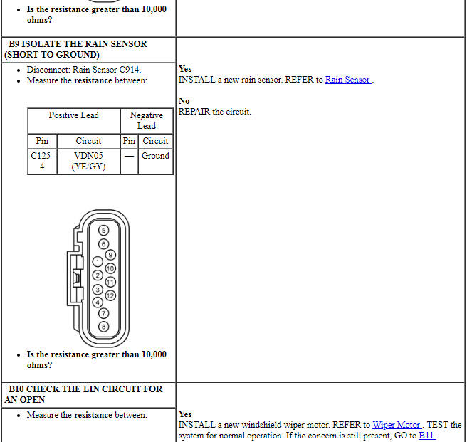
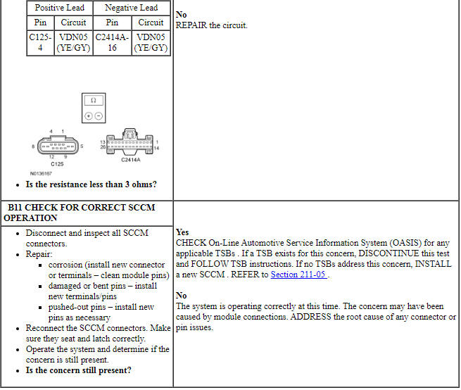
PINPOINT TEST B: THE INTERMITTENT AND/OR LOW SPEED WINDSHIELD WIPERS ARE INOPERATIVE
NOTE:
Pinpoint Test C: The Windshield Wipers Stay On Continuously
Diagnostic Overview
Diagnostics in this manual assume a certain skill level and knowledge of Ford-specific diagnostic practices. REFER to Diagnostic Methods in Section 100-00 for information about these practices.
Refer to Wiring Diagrams Cell 81, Wipers and Washers for schematic and connector information.
Normal Operation and Fault Conditions
REFER to System Operation, Windshield Wipers in Wipers and Washers.
REFER to System Operation, Intermittent Wipers in Wipers and Washers.
REFER to Component Description, Multifunction Switch in Wipers and Washers.
REFER to Component Description, Front Wiper Motor in Wipers and Washers.
-
Possible Sources
- Wiring, terminals or connectors
- Multifunction switch
- Wiper motor
- SCCM
Visual Inspection and Diagnostic Pre-checks
- Inspect the multifunction switch for damage.
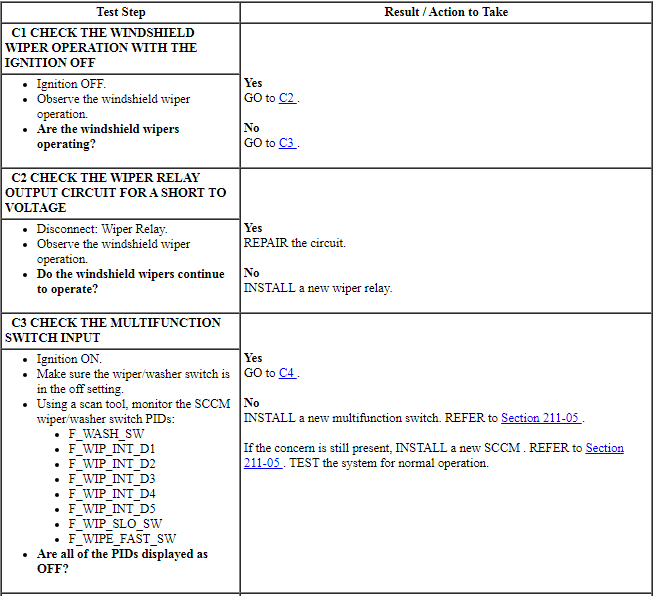
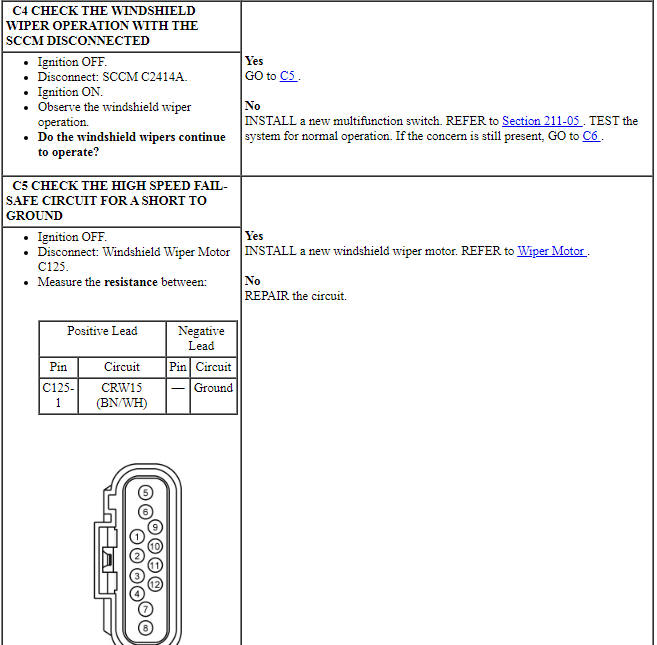
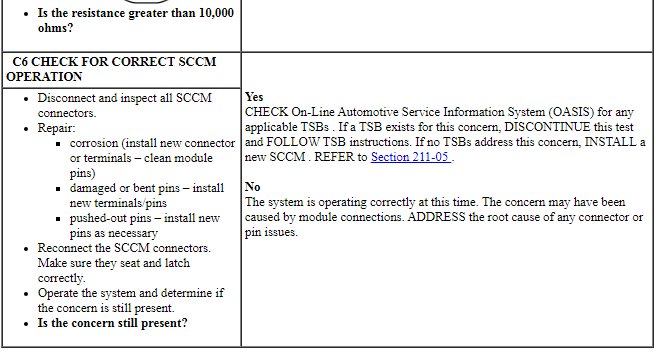
PINPOINT TEST C: THE WINDSHIELD WIPERS STAY ON CONTINUOUSLY
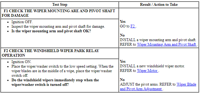
Pinpoint Test D: The Windshield Wipers Do Not Operate Correctly In The Intermittent Mode
Diagnostic Overview
Diagnostics in this manual assume a certain skill level and knowledge of Ford-specific diagnostic practices. REFER to Diagnostic Methods in Section 100-00 for information about these practices.
Refer to Wiring Diagrams Cell 81, Wipers and Washers for schematic and connector information.
Normal Operation and Fault Conditions
REFER to System Operation, Windshield Wipers in Wipers and Washers.
REFER to System Operation, Intermittent Wipers in Wipers and Washers.
REFER to Component Description, Multifunction Switch in Wipers and Washers.
REFER to Component Description, Front Wiper Motor in Wipers and Washers.
-
Possible Sources
- Multifunction switch
- Wiper motor
- SCCM
Visual Inspection and Diagnostic Pre-checks
- Inspect the multifunction switch for damage.
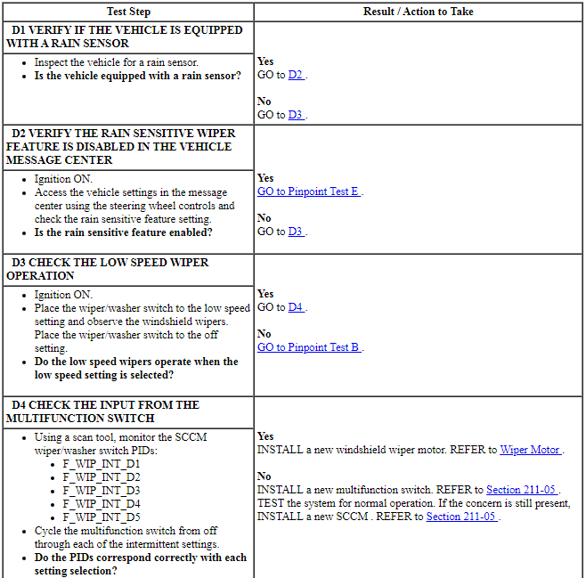
PINPOINT TEST D: THE WINDSHIELD WIPERS DO NOT OPERATE CORRECTLY IN THE INTERMITTENT MODE
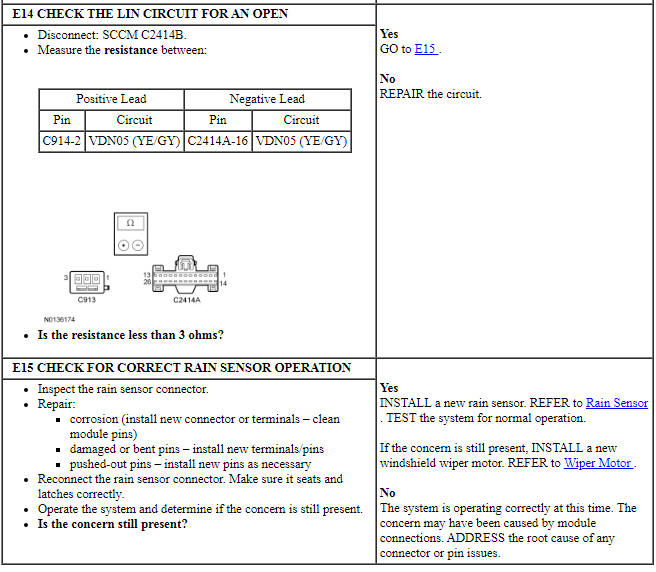
Pinpoint Test E: The Rain Sensitive Wiper Feature Is Inoperative
Diagnostic Overview
Diagnostics in this manual assume a certain skill level and knowledge of Ford-specific diagnostic practices. REFER to Diagnostic Methods in Section 100-00 for information about these practices.
Refer to Wiring Diagrams Cell 81, Wipers and Washers for schematic and connector information.
Normal Operation and Fault Conditions
REFER to System Operation, Windshield Wipers in Wipers and Washers.
REFER to System Operation, Rain Sensitive Wipers in Wipers and Washers.
REFER to Component Description, Multifunction Switch in Wipers and Washers.
REFER to Component Description, Front Wiper Motor in Wipers and Washers.
REFER to Component Description, Rain Sensor in Wipers and Washers.
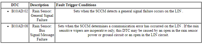
SCCM DTC Fault Trigger Conditions
-
Possible Sources
- Fuse
- Wiring, terminals or connectors
- Rain sensitive feature not enabled
- Foreign material on windshield, such as dirt, dust or bugs
- Wiper blades
- Windshield glass
- Multifunction switch
- Wiper motor
- Rain sensor
Visual Inspection and Diagnostic Pre-checks
- Inspect the windshield for damage.
- Inspect the rain sensor mounting for damage.
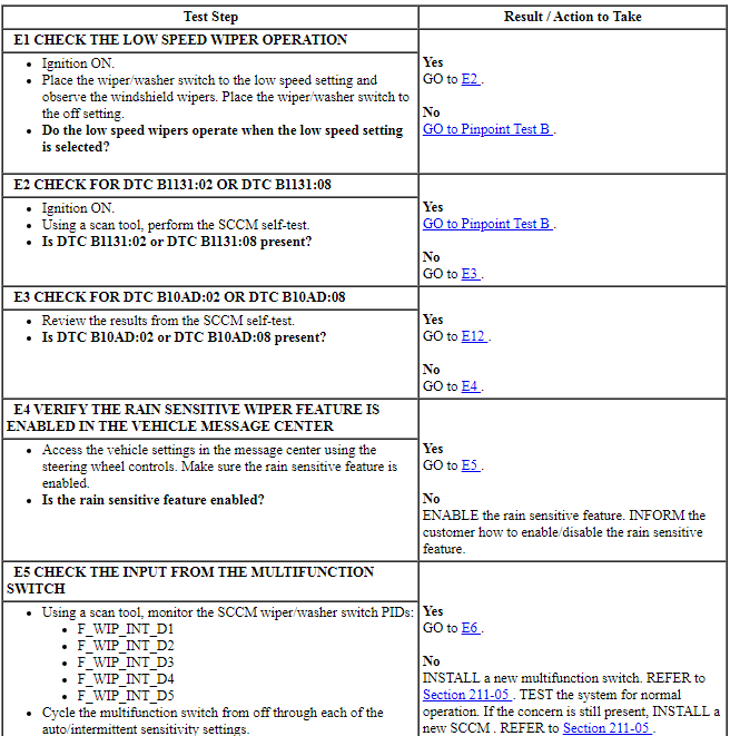
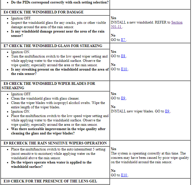
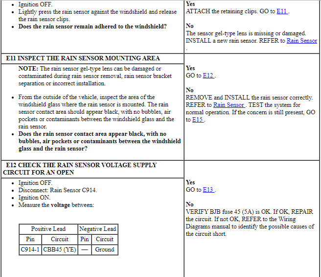
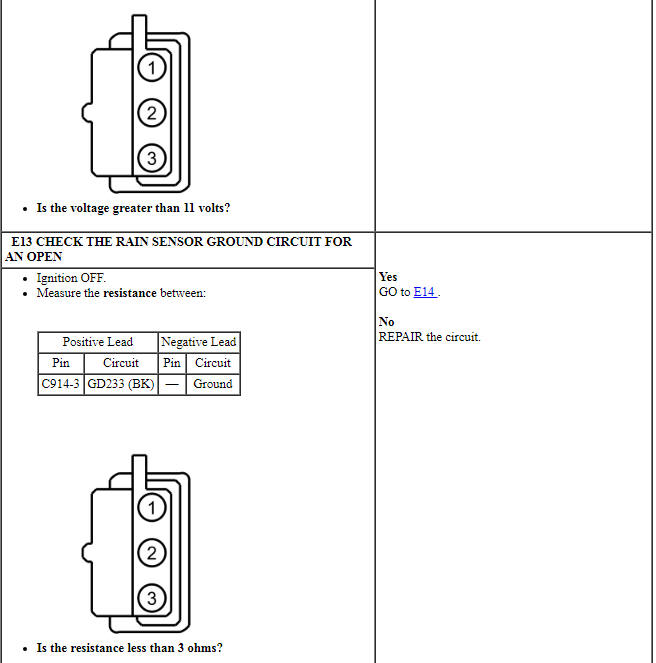
PINPOINT TEST E: THE RAIN SENSITIVE WIPER FEATURE IS INOPERATIVE
Pinpoint Test F: The Windshield Wipers Do Not Park At The Correct Position
Diagnostic Overview
Diagnostics in this manual assume a certain skill level and knowledge of Ford-specific diagnostic practices. REFER to Diagnostic Methods in Section 100-00 for information about these practices.
Refer to Wiring Diagrams Cell 81, Wipers and Washers for schematic and connector information.
Normal Operation and Fault Conditions
REFER to System Operation, Windshield Wipers in Wipers and Washers.
REFER to Component Description, Front Wiper Motor in Wipers and Washers.
-
Possible Sources
- Wiper mounting arm and pivot shaft
- Wiper motor
Visual Inspection and Diagnostic Pre-checks
- Inspect the mounting arm and pivot shaft for damage.
PINPOINT TEST F: THE WINDSHIELD WIPERS DO NOT PARK AT THE CORRECT POSITION
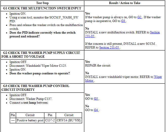
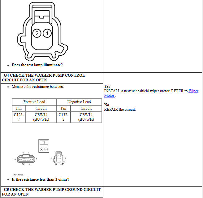
Pinpoint Test G: The Washer Pump Is Inoperative Or Always On
Diagnostic Overview
Diagnostics in this manual assume a certain skill level and knowledge of Ford-specific diagnostic practices. REFER to Diagnostic Methods in Section 100-00 for information about these practices.
Refer to Wiring Diagrams Cell 81, Wipers and Washers for schematic and connector information.
Normal Operation and Fault Conditions
REFER to System Operation, Windshield Wipers in Wipers and Washers.
REFER to System Operation, Windshield Washer in Wipers and Washers.
REFER to Component Description, Multifunction Switch in Wipers and Washers.
REFER to Component Description, Front Wiper Motor in Wipers and Washers.
REFER to Component Description, Washer Pump in Wipers and Washers.
-
Possible Sources
- Wiring, terminals or connectors
- Washer pump
- Multifunction switch
- Wiper motor
- SCCM
Visual Inspection and Diagnostic Pre-checks
- Inspect the multifunction switch for damage.
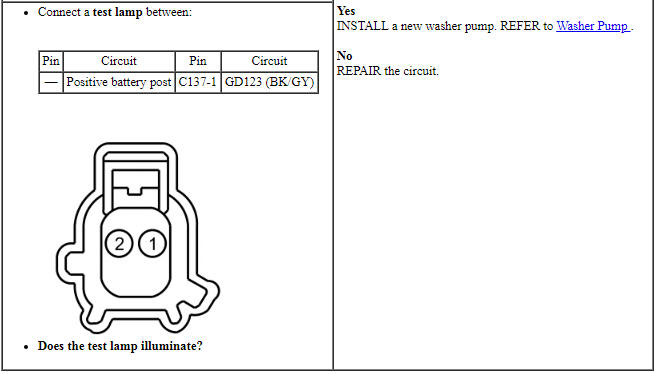
PINPOINT TEST G: THE WASHER PUMP IS INOPERATIVE OR ALWAYS ON
 Specifications, Description and Operation
SPECIFICATIONS
Material
General Specifications
Torque Specifications
DESCRIPTION AND OPERATION
Wipers and Washers
Overview
The windshield wiper/washer system is activated by the wiper/washer contro ...
 General Procedures, Removal and Installation
GENERAL PROCEDURES
Wiper Blade and Pivot Arm Adjustment
Cycle and park the windshield wipers.
Verify that the RH and LH wiper blade tips are aligned to the "I" marks
on the lower windshield gla ...
Other materials:
Vehicle storage
If you plan on storing your vehicle for an extended period of time
(30 days or more), read the following maintenance recommendations to
make sure your vehicle stays in good operating condition.
All motor vehicles and their components were engineered and tested for
reliable, regular driving. Lo ...
Removal and Installation
Main Control Cover
Material
Removal
With the vehicle in NEUTRAL, position it on a hoist. Refer to Section
100-02.
Remove the ACL assembly. Refer to Section 303-12.
Drain the fluid.
Tighten to 12 Nm (106 lb-in).
NOTE: Note ...
Audio System
GENERAL INFORMATION
Radio Frequencies and Reception Factors
AM and FM frequencies are established by the Federal Communications
Commission (FCC) and the Canadian Radio and Telecommunications
Commission (CRTC). Those frequencies are:
AM: 530, 540–1700, 1710 kHz
FM: 87.9–107.7, 107.9 MHz
...
