Antenna - Satellite Radio
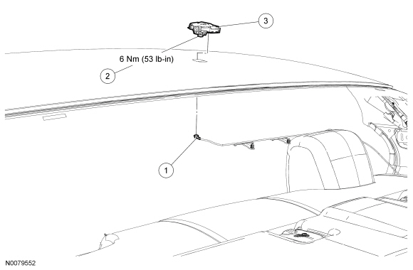
Removal and Installation
NOTE: This procedure applies to both the stand-alone satellite radio antenna and the combination satellite radio/Global Positioning System (GPS) antenna.
- Lower the headliner. For additional information, refer to Section 501-05.
- Remove the satellite radio antenna in the following sequence:
- Disconnect the satellite radio antenna cable connector.
- Loosen the satellite radio antenna bolt.
- To install, tighten to 6 Nm (53 lb-in).
- Remove the satellite radio antenna from the top of the roof.
- To install, reverse the removal procedure.
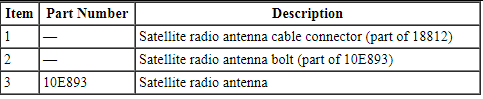
Antenna Cable - Satellite Radio
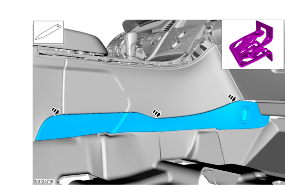
Rear Satellite Radio Antenna Cable
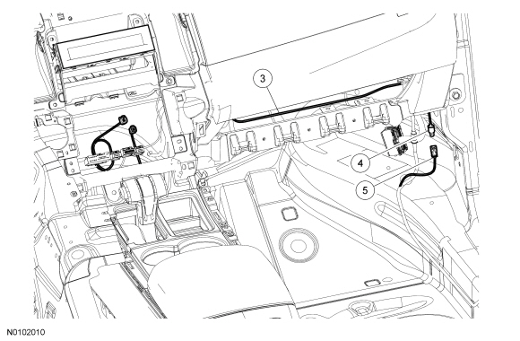
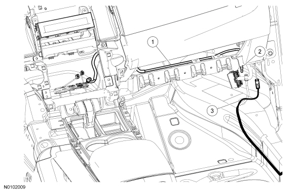
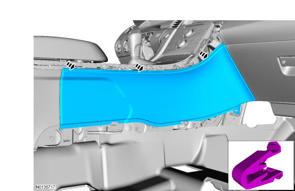
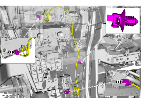
Front And Middle Satellite Radio Antenna Cables
NOTE: The front satellite radio antenna cable with navigation is shown.
NOTE: The glove compartment is shown removed for clarity.
Removal
NOTE: The satellite radio antenna cables are part of the vehicle wiring harness. Because the cables cannot be removed from the harness, this procedure applies to replacement of the cables only.
NOTE: For vehicles with navigation, a splitter is built-in to the front satellite radio antenna cable to split the satellite radio and Global Positioning System (GPS) signals.
Front cable
- Remove the Audio Front Control Module (ACM). For additional information, refer to Audio Control Module (ACM) in this section.
Rear cable
- Lower the headliner. For additional information, refer to Section 501-05.
- Disconnect the cable from the antenna.
Middle cable
- Remove the RH front and RH rear sill panels by pulling straight upward.
All cables
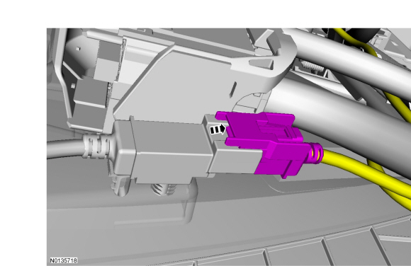
- Disconnect the appropriate satellite radio antenna cable in-line connection(s).
- Cut the ends of the existing cable and tape them back to prevent NVH concerns.
Installation
All cables
- Overlay the new satellite radio antenna cable on the vehicle wiring harness, following the routing of the original cable.
- Secure the new satellite radio antenna cable with tape or zip ties, as
necessary.
- For the front satellite radio antenna cable on vehicles with navigation, secure the splitter using the built-in push-pins.
- Connect the appropriate satellite radio antenna cable in-line connection(s).
Front cable
- Install the ACM. For additional information, refer to Audio Control Module (ACM) in this section.
Middle cable
- Install the RH front and RH rear sill panels.
Rear cable
- Connect the rear satellite radio antenna cable to the antenna.
- Install the headliner. For additional information, refer to Section 501-05.
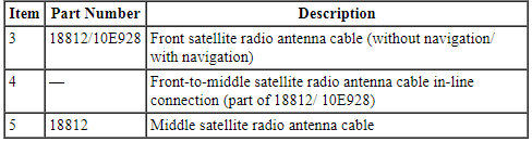
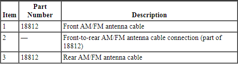
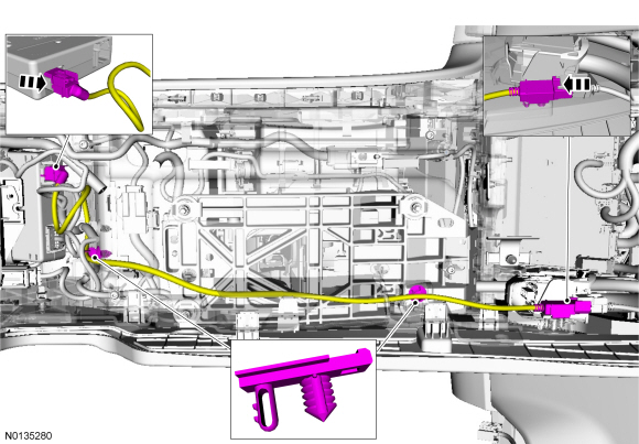
Antenna Cable - AM/FM
NOTE: Only the front AM/FM antenna cable is shown.
NOTE: The glove compartment is shown removed for clarity.
Removal
NOTE: Both the front and rear AM/FM antenna cables are part of the vehicle wiring harness. Because the cables cannot be removed from the harness, this procedure applies to replacement of the cables only.
Front cable
- Remove the Audio Front Control Module (ACM). For additional information, refer to Audio Control Module (ACM) in this section.
Rear cable
- Lower the headliner. For additional information, refer to Section 501-05.
- Disconnect the rear AM/FM antenna cable from the antenna module.
- Remove the RF and RR door sill trim panels. For additional information, refer to Section 501-05.
Both cables
- Disconnect the front-to-rear AM/FM antenna cable connection at the RH kick panel.
- Cut the ends of the existing cable and tape them back to prevent NVH concerns.
Installation
Both cables
- Overlay the new AM/FM antenna cable on the vehicle wiring harness, following the routing of the original cable.
- Secure the new AM/FM antenna cable with tape or zip ties, as necessary.
- Connect the front-to-rear AM/FM antenna cable connection at the RH kick panel.
Front cable
- Install the ACM. For additional information, refer to Audio Control Module (ACM) in this section.
Rear cable
- Install the RF and RR door sill trim panels. For additional information, refer to Section 501-05.
- Connect the rear AM/FM antenna cable to the antenna module.
- Install the headliner. For additional information, refer to Section 501-05.
Antenna Module
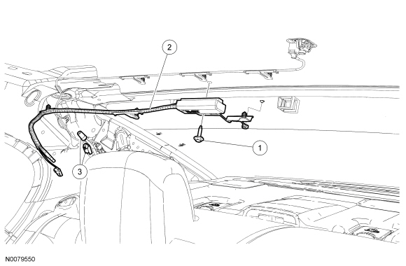
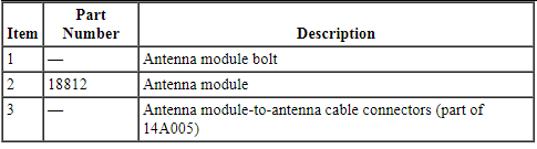
Removal and Installation
- Lower the headliner. For additional information, refer to Section 501-05.
- Disconnect the antenna module-to-antenna cable connectors.
- Remove the bolt and the antenna module.
- To install, reverse the removal procedure.
Audio Control Module (ACM)
NOTE: Without navigation shown, with navigation similar.
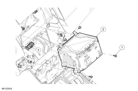
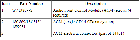
Removal and Installation
NOTE: It is not necessary to remove the Audio Front Control Module (ACM) to retrieve the part number. For additional information, refer to Audio Control Module (ACM) Self-Diagnostic Mode in this section.
- NOTE: Module configuration is required when a new ACM is being
installed.
Upload the ACM configuration information to the scan tool. For additional information, refer to Programmable Module Installation (PMI) in Section 418-01.
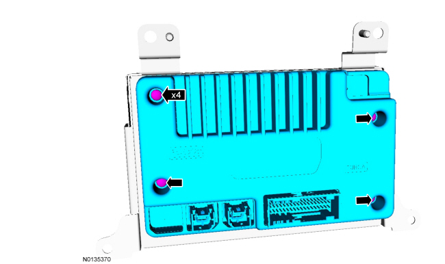
- Remove the Front Display Interface Module (FDIM). For additional information, refer to Front Display Interface Module (FDIM) in this section.
- Remove the 4 screws and the ACM.
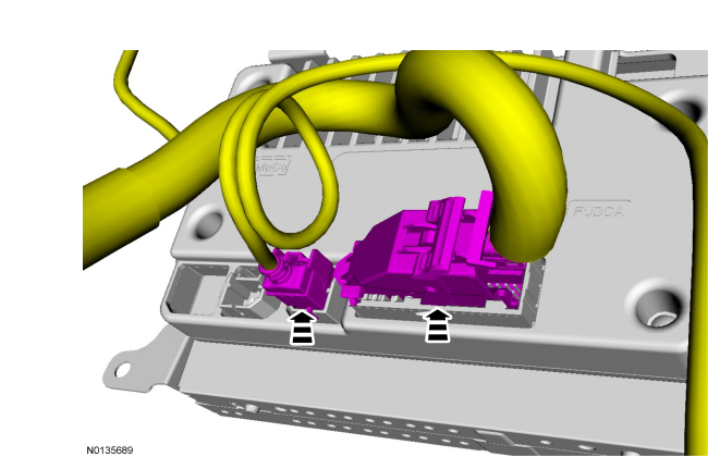
- Disconnect the electrical connectors.
- To install, reverse the removal procedure.
- Download the ACM configuration information from the scan tool. For additional information, refer to PMI in Section 418-01.
Audio Digital Signal Processing (DSP) Module
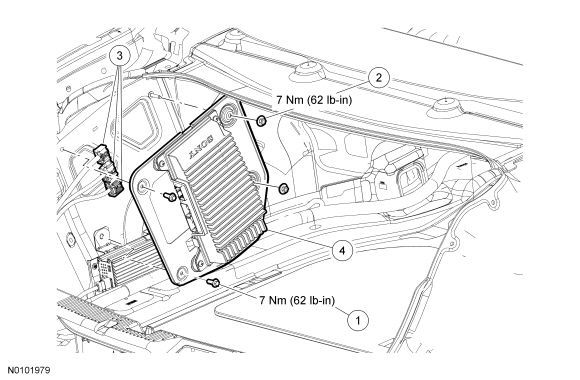
Removal and Installation
- NOTE: Module configuration is required when a new audio Digital
Signal Processing (DSP) module is being installed.
Upload the audio DSP module configuration to the scan tool. For additional information, refer to Programmable Module Installation (PMI) in Section 418-01.
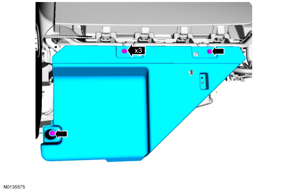
- Remove the retainers and pull back the LH luggage compartment trim panel. For additional information, refer to Section 501-05.
- Disconnect the audio DSP module electrical connectors.
- Remove the 2 bolts, the 2 nuts, and the audio DSP module.
- To install, tighten to 9 Nm (80 lb-in).
- To install, reverse the removal procedure.
- Download the configuration information to the audio DSP module. For additional information, refer to PMI in Section 418-01.
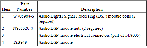
Front Controls Interface Module (FCIM)
Removal and Installation
- Remove the center instrument panel finish panel. For additional information, refer to Section 501-12.
- Release the 4 center register clips and remove the center registers.
- To install, reverse the removal procedure.
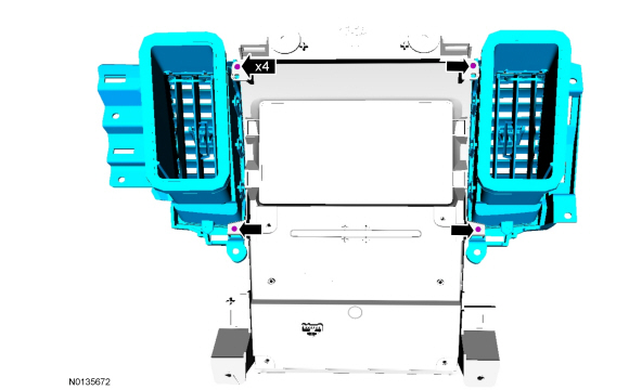
Front Display Interface Module (FDIM)
Removal and Installation
- Remove the center instrument panel finish panel. For additional information, refer to Section 501-12.
- Remove the 4 screws and the Front Display Interface Module (FDIM).
- To install, tighten to 2.5 Nm (23 lb-in).
- Disconnect the Accessory Protocol Interface Module (APIM) electrical connectors.
- Remove the 4 screws and remove APIM from the FDIM.
- To install, tighten to 0.6 Nm (5 lb-in).
- To install, reverse the removal procedure.
- Calibrate the FDIM touchscreen. Refer to Touchscreen Calibration.
Global Positioning System Module (GPSM)
NOTE: Steering wheel shown removed for clarity only.
Removal and Installation
NOTE: Prior to replacement of the module, it is necessary to upload the module configuration information to the appropriate scan tool. This information must be downloaded into the new module after installation. For additional information, refer to Section 418-01.
- NOTE: This step is necessary only if the GPSM is being replaced. Upload the module configuration information from the GPSM into the scan tool. For additional information, refer to Section 418-01.
- Remove the Instrument Panel Cluster (IPC). For additional information, refer to Section 413-01.
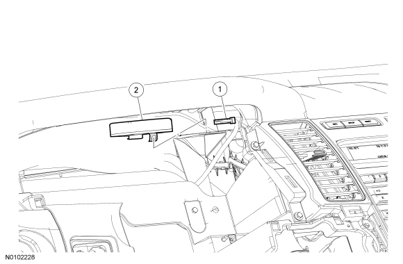
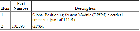
- Release the clip and remove the Global Positioning System Module (GPSM).
- Disconnect the electrical connector.
- NOTE: If installing a new GPSM, make sure to download the GPSM configuration
information from the scan tool into the new GPSM. For additional
information, refer to Section 418-01.
To install, reverse the removal procedure.
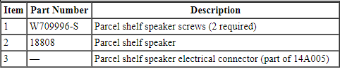
Speaker - Door
NOTE: Front door shown, rear door similar.
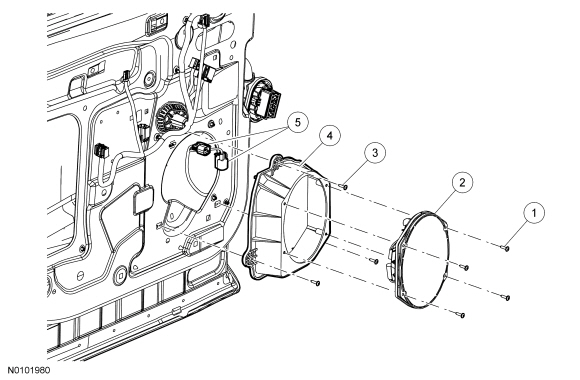
Removal and Installation
- Remove the door trim panel. For additional information, refer to Section 501-05.
- Remove the 4 screws and the door speaker.
- Disconnect the electrical connector(s).
- If removing the bracket, remove the 3 screws and the door speaker bracket.
- To install, reverse the removal procedure.
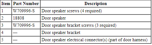
Speaker - Parcel Shelf, Center
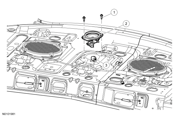
Removal and Installation
- Remove the parcel shelf. For additional information, refer to Section 501-05.
- Remove the 2 screws and the parcel shelf speaker.
- Disconnect the electrical connector.
- To install, reverse the removal procedure.
Speaker - Subwoofer
NOTE: RH side shown, LH side similar.
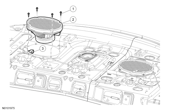
Removal and Installation
- Remove the parcel shelf. For additional information, refer to Section 501-05.
- Remove the 4 screws and the subwoofer speaker.
- Disconnect the electrical connector.
- To install, reverse the removal procedure.
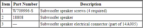
Speaker - Instrument Panel
Removal and Installation
- Using a suitable tool such as a trim removal tool, remove the instrument panel speaker cover by prying upward to disengage the clips.
- Remove the 2 screws and the instrument panel speaker.
- Disconnect the electrical connector.
- To install, reverse the removal procedure.
Speaker - A-Pillar
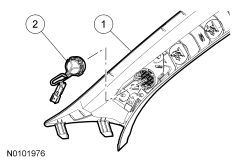
Removal and Installation
- Remove the A-pillar trim panel. For additional information, refer to Section 501-05.
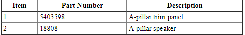
- Release the clips and remove the A-pillar speaker.
- To install, reverse the removal procedure.
Accessory Protocol Interface Module (APIM)
Removal
- Remove the Front Display Interface Module (FDIM). For additional information, refer to Front Display Interface Module (FDIM).
- Remove the 4 screws and remove the APIM from the FDIM.
- To install, tighten to 0.6 Nm (5 lb-in).

Installation
- To install, reverse the removal procedure.
- Program the APIM. For additional information, refer to Accessory Protocol Interface Module (APIM) Programming - Module Replacement.
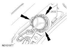
Universal Serial Bus (USB) Cable and Port
Upper USB cable
- Remove the Accessory Protocol Interface Module (APIM) and disconnect the USB cable. For additional information, refer to Accessory Protocol Interface Module (APIM).
- Remove the floor console RH finish moulding.
- Disconnect the electrical connector.
- Remove the floor console RH lower trim panel.
- Remove the floor console RH upper trim panel.
- Disconnect the USB cable at the lower RH side of the floor console.
- Remove the hush panel from the lower RH side of the instrument panel.
- Detach the retainers and remove the USB cable following the routing shown.
Lower USB cable
- Remove the floor console. For additional information, refer to Section 501-12.
- If equipped, remove the 6 screws and the floor console air duct.
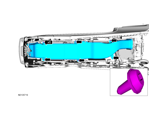
- Detach the retainers and remove the USB cable following the routing shown.
Both cables
- To install, reverse the removal procedure.
Microphone
Removal
- Pry the microphone bezel from the headliner metal mounting bracket and
remove the microphone from the headliner by grasping the microphone pigtail.
- Disconnect the electrical connector.
Installation
- Connect the microphone electrical connector.
- Wrap the connection with anti-rattle tape.
- Feed the microphone pigtail into the headliner through the microphone
hole.
- Verify the microphone pigtail points towards the front of the vehicle.
- Snap the microphone into the headliner mounting bracket.
- Verify the mounting bracket and microphone are snug to the headliner.
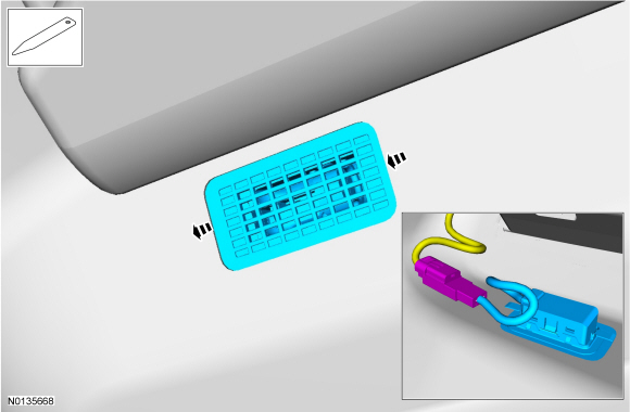
Media Hub
Removal and Installation
- Open the floor console stowage bin door.
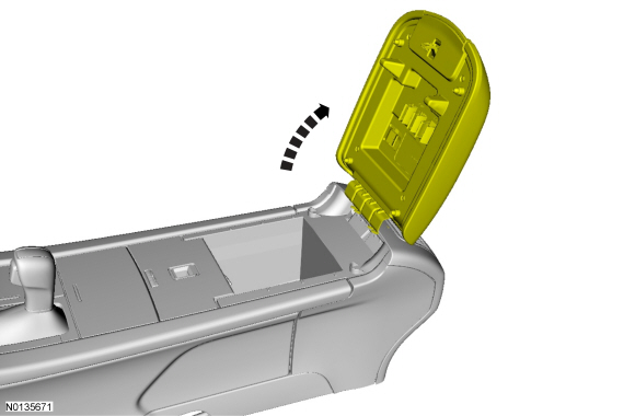
- Using a trim removal tool, remove the audio input jack bezel by prying
straight back.
- Disconnect the electrical connectors.

- To install, reverse the removal procedure.
 General Procedures
Audio Control Module (ACM) Self-Diagnostic Mode
NOTE: If the Audio Front Control Module (ACM) is completely
inoperative (does not power up), the part number decal on the Audio Front
Control Mod ...
 Lighting
...
Other materials:
Diagnosis and Testing
Handles, Locks, Latches and Entry Systems
Special Tool(s)
Material
DTC Charts
Diagnostics in this manual assume a certain skill level and knowledge of
Ford-specific diagnostic practices. Refer to Diagnostic Methods in Section
100-00 for information about these practices.
DDM DTC C ...
Tire Pressure Monitoring System (TPMS)
WARNING: The tire pressure monitoring system is NOT a
substitute for manually checking tire pressure. The tire pressure
should be checked periodically (at least monthly) using a tire gauge.
See Inflating Your Tires in this chapter. Failure to properly maintain
your tire pressure could increase ...
Child Safety
• You are required by law to properly use safety seats for infants and
toddlers in the United States and Canada.
• Many states and provinces require that small children use approved
booster seats until they reach age eight, a height of 4 feet 9 inches
(1.45 meters) tall, or 80 pounds (36 ...
