DESCRIPTION AND OPERATION
Universal Transmitter
Overview
The universal transmitter operates garage doors, gates and home or office lighting and security systems.
System Operation
Universal Home Transmitter
The universal transmitter learns a hand-held transmitter radio frequency code and stores the code in memory. It consists of 3 buttons, each with its own indicator lamp. Once the universal transmitter code is stored, the universal transmitter emits the radio frequency of the hand-held transmitter when the corresponding button is pressed. The universal transmitter can store 3 unique transmitter codes at a time. The universal transmitter and LH vanity mirror lamp share the same power and ground circuits. Both components are part of the LH sun visor.
DIAGNOSIS AND TESTING
Universal Transmitter
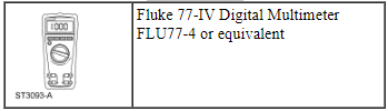
Special Tool(s)
Inspection and Verification
- Verify the customer concern.
- Visually inspect for obvious signs of mechanical or electrical damage.
Visual Inspection Chart

- If an obvious cause for an observed or reported concern is found, correct the cause (if possible) before proceeding to the next step.
- If the cause is not visually evident, verify the symptom. GO to Symptom Chart.
Symptom Chart
Pinpoint Tests
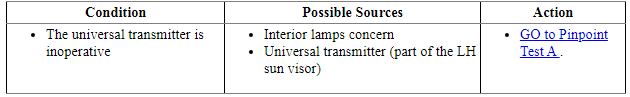
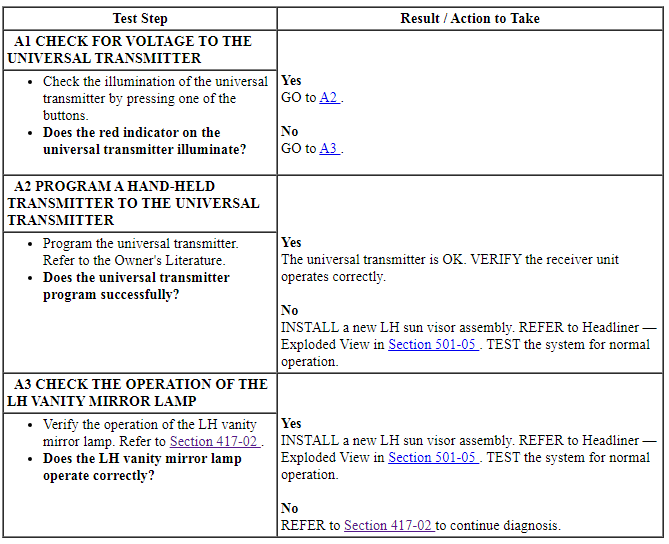
Pinpoint Test A: The Universal Transmitter is Inoperative
Normal Operation
The universal transmitter and LH vanity mirror lamp share the same circuits. Both components are part of the LH sun visor.
This pinpoint test is intended to diagnose the following:
- Interior lamps concern
- Universal transmitter (part of the LH sun visor)
PINPOINT TEST A: THE UNIVERSAL TRANSMITTER IS INOPERATIVE
 Anti-Theft - Passive Anti-Theft System (PATS), With Intelligent Access (IA)
DESCRIPTION AND OPERATION
Anti-Theft
Component Location
RFA Module
Backup Transceiver
TPM Module
Passive Start Antenna (3 required)
Overview
PATS deters the vehicle from theft by ...
 Cruise Control - Non-Adaptive
DESCRIPTION AND OPERATION
Cruise Control
Overview
The cruise control system is controlled by the PCM. The cruise control mode
is selected from the steering wheel mounted switches (ON/OFF, SET, CNCL a ...
Other materials:
Removal and Installation
Antenna - Satellite Radio
Removal and Installation
NOTE: This procedure applies to both the stand-alone satellite radio
antenna and the combination satellite radio/Global Positioning System (GPS)
antenna.
Lower the headliner. For additional information, refer to Section
501-05.
...
Normal scheduled maintenance and log
Intelligent Oil-Life Monitor®
Your vehicle is equipped with an Intelligent Oil-Life Monitor that
determines when the engine oil needs to be changed based on how your
vehicle is used. By using several important factors in its calculations,
the monitor helps reduce the cost of owning your vehicle ...
Removal and Installation
Clockspring
Removal and Installation
WARNING: If
the clockspring is not correctly centralized, it may fail prematurely. If in
doubt, repeat the centralizing procedure. Failure to follow these instructions
may increase the risk of serious personal injury or death in a crash.
NOTE: Remov ...
