DESCRIPTION AND OPERATION
Interior Lighting
Overview
The interior lighting system consists of:
- Courtesy lamps
- Demand lamps
- Ambient lighting (if equipped)
The courtesy lamps subsystem consists of:
- Interior lamps
- Puddle lamps
- Door ajar switches (integrated into the door latches)
- Instrument panel dimmer switch
- SCCM
- BCM
The courtesy lamps provide illumination to the interior of the vehicle when entering or exiting the vehicle or when requested using the instrument panel dimmer switch.
The demand lamps subsystem consists of:
- Interior lamps
- Vanity mirror lamps
- Luggage compartment lamp (if equipped)
- Glove compartment lamp
- BCM
The demand lamps are used to provide illumination to specific areas within the vehicle when needed. The BCM energizes the battery saver relay to supply voltage to the demand lamps when the battery saver feature is not active.
The ambient lighting subsystem consists of:
- Ambient lighting harnesses
- HVAC module
- APIM
- FDIM
The ambient lighting provides aesthetically colored illumination to the center console cup holders, the door map pockets, the door pull handles, the door release handles, and the front and rear footwells for illuminated entry or when the ignition is in run with the parking lamps on. The ambient lighting is controlled using the touchscreen display in the center of the instrument panel.
System Operation
System Diagram
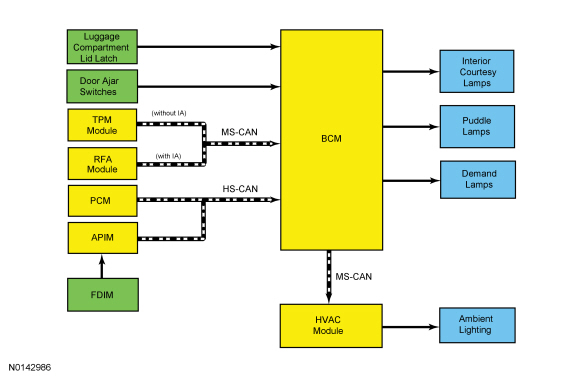
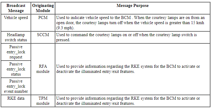
Network Message Chart
Module Network Input Messages - BCM
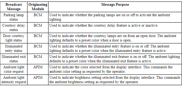
Module Network Input Messages - HVAC Module
Battery Saver
NOTE: The battery saver time-out is 1 minute if the vehicle has less than 201 km (125 mi).
NOTE: The battery saver does not control the parking lamps if the headlamp switch is in the PARKING LAMPS ON position.
To save battery voltage, the BCM provides automatic shut-off of the interior and exterior lamps after a time-out period when the ignition is off. The BCM monitors the ignition state and input from the RKE system to determine when to energize or de-energize the battery saver relay and to shut the power off to the lamps. A timer in the BCM starts when:
- the ignition changes to OFF.
- any door becomes ajar while the ignition is off.
- an UNLOCK button of the RKE transmitter is pressed while the ignition is off.
- a valid keypad code is entered while the ignition is off.
- or the courtesy lamp switch is used to turn the courtesy lamps on while the ignition is off.
When 10 minutes have elapsed, the BCM automatically shuts off voltage to the lamps. The timer restarts (voltage is restored if the BCM is in battery saver mode) if:
- the ignition transitions out of OFF.
- any door becomes ajar.
- the UNLOCK button of the RKE transmitter is pressed.
- a valid keypad code is entered.
- the instrument panel dimmer switch is in the interior lamps ON position.
Courtesy Lamps
The BCM controls all the interior lighting functions and timing by monitoring inputs from the:
- door ajar switches
- ignition state
- instrument panel dimmer switch
- RKE system
- vehicle speed
The BCM sends a 12 volt signal to each door ajar switch. When the doors are closed, the voltage signals are pulled low, indicating a closed door.
The BCM monitors input from the RKE transmitter (messaged from the TPM module on vehicles without IA or from the RFA module on vehicles with IA ) to determine when to activate/deactivate the illuminated entry feature.
The BCM monitors the ignition state to determine when to activate/deactivate the illuminated exit feature.
Based on the input, the BCM controls the solid state relays to provide power to the courtesy lamps.
The BCM also provides an overload protection of the interior courtesy and puddle lamp output circuits. When an excessive current draw is detected, the BCM disables the affected interior courtesy or puddle lamp circuit driver.
Illuminated Entry
The illuminated entry requests the dimmable backlighting, the parking lamps and the courtesy lamps to illuminate when the ignition is off and a door is opened, the RKE transmitter UNLOCK button is pressed, or the vehicle is unlocked using the keyless entry keypad. If no doors are open, the illuminated entry requests the lamps off after 25 seconds have elapsed, the ignition is switched out of off, the RKE transmitter LOCK button is pressed, or the vehicle is locked using the keyless entry keypad.
Interior Lighting Delay
The interior lighting delay feature provides temporary illumination of the dimmable backlighting, the parking lamps and the courtesy lamps after the doors are opened and then closed. The interior lighting delay feature keeps the lamps on for a period of 25 seconds after all the doors are closed. If during the 25 second delay time the ignition has been switched out of off, or if the vehicle is locked using the RKE transmitter or the keyless entry keypad, the lamp illumination is discontinued.
Illuminated Exit
The illuminated exit requests the dimmable backlighting, the parking lamps, and the courtesy lamps to illuminate for 25 seconds after all doors are closed and the ignition is turned off. The illuminated exit deactivates when the ignition transitions out of off, a door becomes ajar, or 25 seconds have elapsed.
Theater Lighting
The theater lighting feature ramps-up the courtesy lamps over 0.7 second when courtesy lamp activation is requested. The theater lighting feature ramps-down the courtesy lamps over 1.7 seconds when interior lighting deactivation is requested by any feature other than the panic alarm or battery saver.
Interior Lamp Arbitrator
The interior lamp arbitrator (programming within the BCM ) chooses between the interior lighting delay, the illuminated entry and exit, the battery saver, and the alarm flash processing to determine which feature has precedence of activating and deactivating the interior lamps.
Demand Lamps
The BCM monitors the ignition state and inputs from the RKE system to determine when to energize the battery saver relay. When the battery saver relay is energized, voltage is provided to the demand lamps.
When the BCM is not in battery saver mode, the battery saver relay is energized to provide voltage to the demand lamps.
Ambient Lighting
The HVAC module provides the power and ground to the ambient lighting system, while the touchscreen is used to cycle through the different color variations or turn the ambient lighting feature on or off. There are 3 LEDs (red, blue and green) housed within each LED assembly. By illuminating various color combinations, the LED are able to produce 7 different colors of ambient light.
The ambient lighting LEDs provide illumination to the:
- cupholders (located in the center console)
- storage compartment (located in the center console)
- front footwells (located under the instrument panel)
- rear footwells (located in the rear of the center console)
The APIM uses software to monitor the user interface from the FDIM. Based on the ambient lighting system selections made using the touchscreen, the APIM sends ambient light color request and ambient light intensity request messages over the communication network for color and brightness settings. The HVAC module retains the last color and brightness setting between uses.
The BCM transmits parking lamps on, illuminated entry/exit feature active, and open door information over the communication network to the HVAC module.
Based on the input received from the FDIM (user preferences) and the BCM (parking lamps on, illuminated entry/exit, open door) over the communication network, the HVAC module provides voltage to the ambient lighting LEDs. The HVAC module also provides the ground source for the ambient lighting LEDs.
Dark Car Feature
The dark car feature disables activation of courtesy lamps and backlighting due to a door unlock, door ajar or removing the key from the ignition cylinder. The courtesy lamps may still be activated by the instrument panel dimmer switch, post crash alert, and perimeter and panic alarms.
The dark car feature is enabled/disabled through programmable parameters in the BCM.
Component Description
Door Ajar Switch
The door ajar switches (ground switches) each receive a voltage signal from the BCM on independent circuits. When the door is closed, the door ajar switch is closed, routing the signal to ground. When the door is opened, the door ajar switch opens.
Luggage Compartment Lid Latch
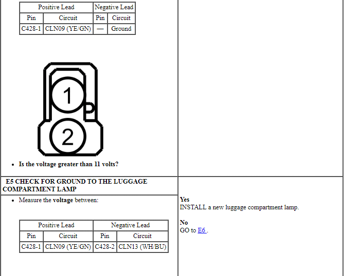
The luggage compartment lid latch contains a switch (ground switches) that receive a voltage signal from the BCM through the luggage compartment bulb. When the luggage compartment lid is open, the switch routes the signal to ground.
DIAGNOSIS AND TESTING
Interior Lighting
DTC Charts
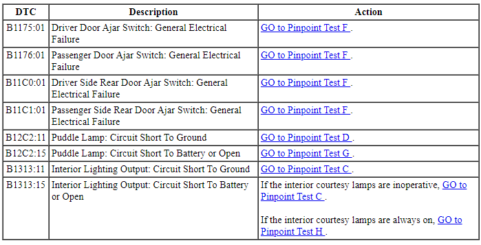
BCM DTC Chart
HVAC Module DTC Chart
Symptom Chart
Pinpoint Tests
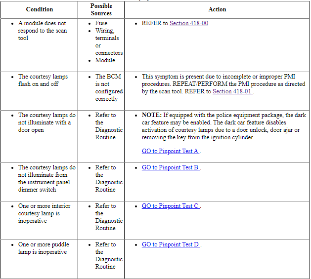
Pinpoint Test A: The Courtesy Lamps Do Not Illuminate With A Door Open
Diagnostic Overview
Diagnostics in this manual assume a certain skill level and knowledge of Ford-specific diagnostic practices. Refer to Diagnostic Methods in Section 100-00 for information about these practices.
Refer to Wiring Diagrams Cell 89, Interior Lamps for schematic and connector information.
Normal Operation and Fault Conditions
REFER to Courtesy Lamps in Interior Lighting.
-
Possible Sources
- Wiring, terminals or connectors
- Door latch
- BCM
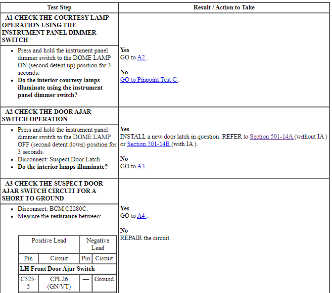
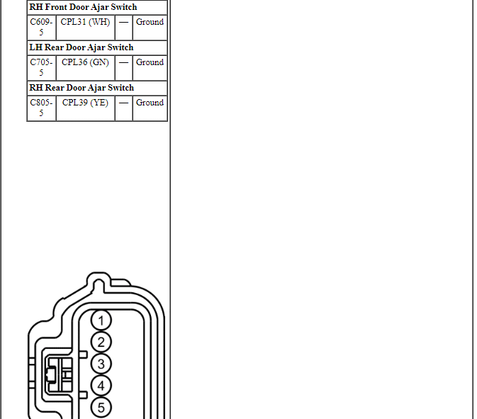
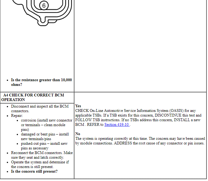
PINPOINT TEST A: THE COURTESY LAMPS DO NOT ILLUMINATE WITH A DOOR OPEN
NOTE: Make sure that the dark car feature is not enabled in the BCM. The dark car feature disables activation of courtesy lamps due to a door unlock, door ajar or removing the key from the ignition cylinder. The feature can be disabled using a scan tool.
Pinpoint Test B: The Courtesy Lamps Do Not Illuminate From The Instrument Panel Dimmer Switch
Diagnostic Overview
Diagnostics in this manual assume a certain skill level and knowledge of Ford-specific diagnostic practices. Refer to Diagnostic Methods in Section 100-00 for information about these practices.
Refer to Wiring Diagrams Cell 89, Interior Lamps for schematic and connector information.
Normal Operation and Fault Conditions
REFER to Courtesy Lamps in Interior Lighting.
-
Possible Sources
- Wiring, terminals or connectors
- Instrument panel dimmer switch
- BCM
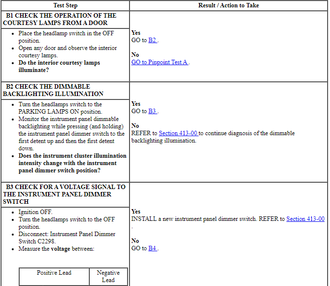
PINPOINT TEST B: THE COURTESY LAMPS DO NOT ILLUMINATE FROM THE INSTRUMENT PANEL DIMMER SWITCH
Pinpoint Test C: One Or More Interior Courtesy Lamp Is Inoperative
Diagnostic Overview
Diagnostics in this manual assume a certain skill level and knowledge of Ford-specific diagnostic practices. Refer to Diagnostic Methods in Section 100-00 for information about these practices.
Refer to Wiring Diagrams Cell 89, Interior Lamps for schematic and connector information.
Normal Operation and Fault Conditions
REFER to Courtesy Lamps in Interior Lighting.
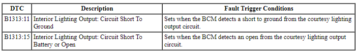
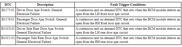
DTC Fault Trigger Conditions
-
Possible Sources
- BCM fuse 12 (15A)
- Wiring, terminals or connectors
- Interior lamp
- BCM
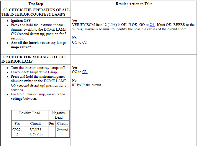
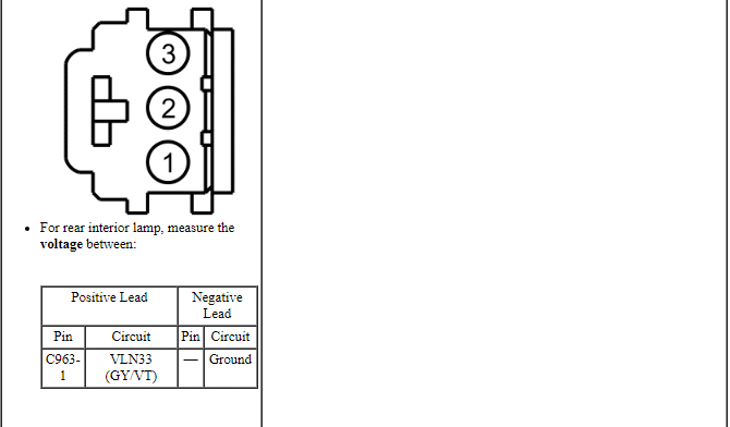
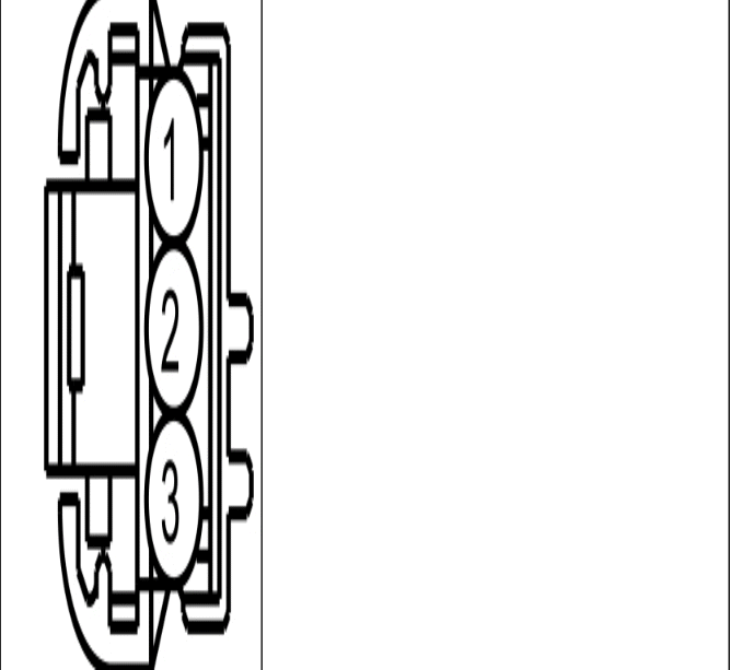
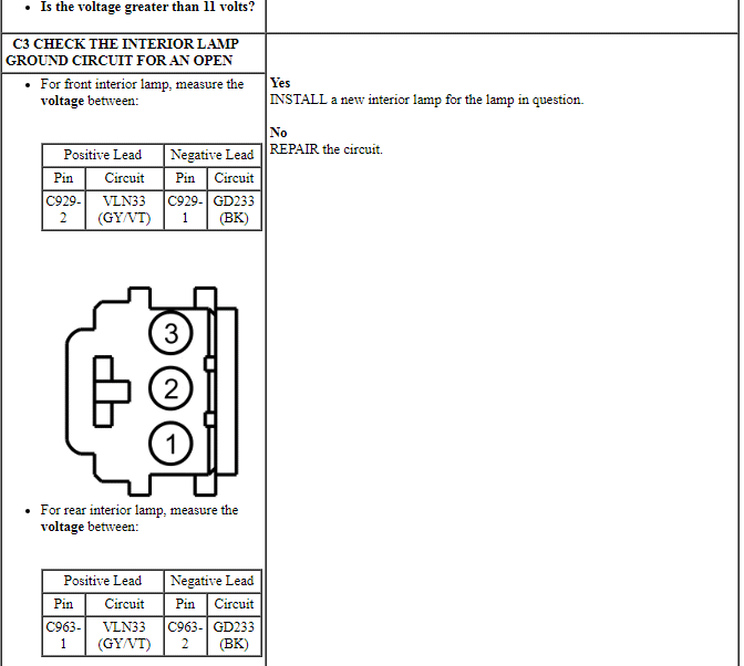
PINPOINT TEST C: ONE OR MORE INTERIOR COURTESY LAMP IS INOPERATIVE
NOTE: After any repair:
If BCM DTC U1000:00 is present, CLEAR the DTCs and REPEAT the self-test (required to enable the low beam output driver if DTC U1000:00 is present).
If BCM DTC U3000:49 is present, INSTALL a new BCM. REFER to Section 419-10.
Pinpoint Test D: One Or More Puddle Lamp Is Inoperative
Diagnostic Overview
Diagnostics in this manual assume a certain skill level and knowledge of Ford-specific diagnostic practices. Refer to Diagnostic Methods in Section 100-00 for information about these practices.
Refer to Wiring Diagrams Cell 89, Interior Lamps for schematic and connector information.
Normal Operation and Fault Conditions
REFER to Courtesy Lamps in Interior Lighting.
DTC Fault Trigger Conditions

-
Possible Sources
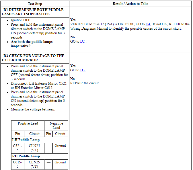
- BCM fuse 12 (15A)
- Wiring, terminals or connectors
- Puddle lamp
- Exterior mirror
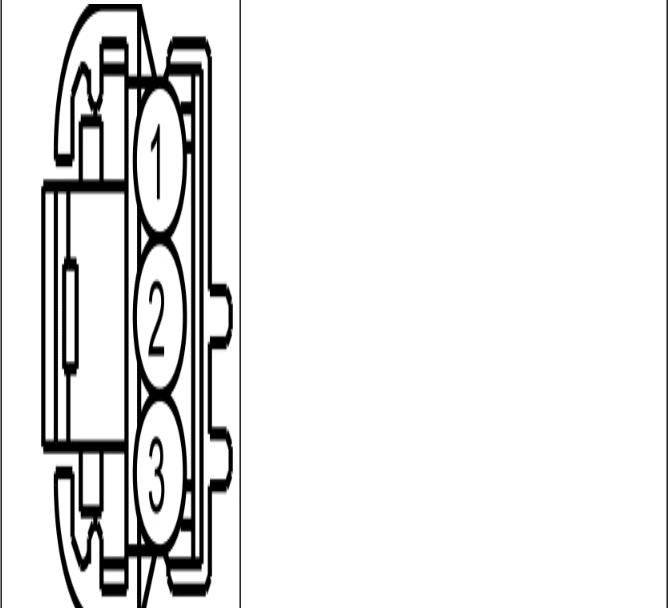
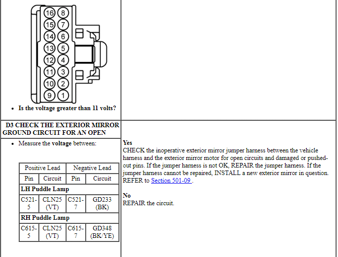
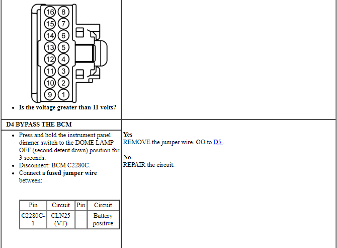
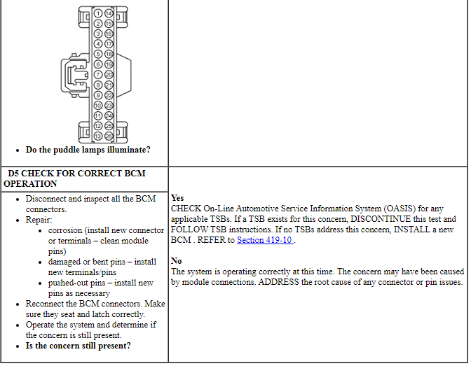
PINPOINT TEST D: ONE OR MORE PUDDLE LAMP IS INOPERATIVE
NOTE: After any repair:
If BCM DTC U1000:00 is present, CLEAR the DTCs and REPEAT the self-test (required to enable the low beam output driver if DTC U1000:00 is present).
If BCM DTC U3000:49 is present, INSTALL a new BCM. REFER to Section 419-10.
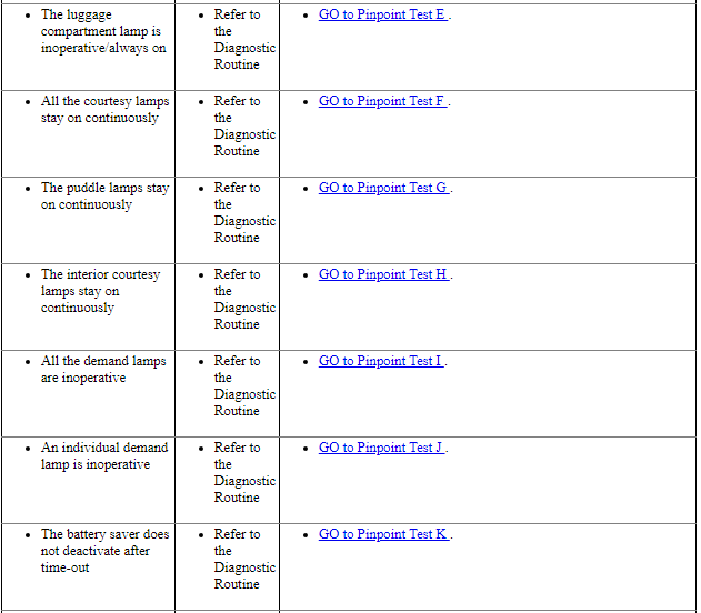
Pinpoint Test E: The Luggage Compartment Lamp Is Inoperative/Always On
Diagnostic Overview
Diagnostics in this manual assume a certain skill level and knowledge of Ford-specific diagnostic practices. Refer to Diagnostic Methods in Section 100-00 for information about these practices.
Refer to Wiring Diagrams Cell 89, Interior Lamps for schematic and connector information.
Normal Operation and Fault Conditions
REFER to Interior Lighting.
-
Possible Sources
- Wiring, terminals or connectors
- Luggage compartment lamp
- Luggage compartment lid latch
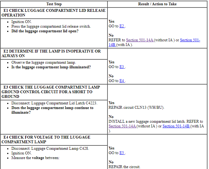
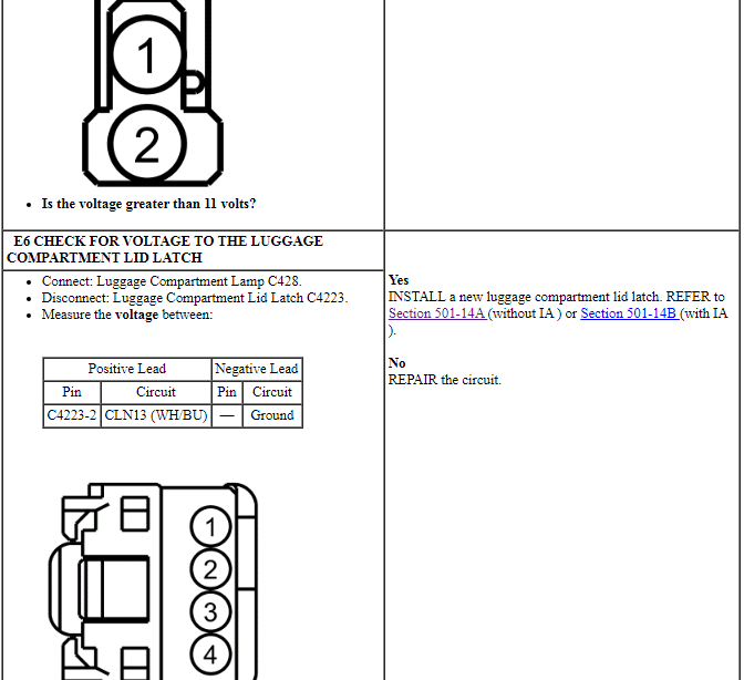
PINPOINT TEST E: THE LUGGAGE COMPARTMENT LAMP IS INOPERATIVE/ALWAYS ON

Pinpoint Test F: All The Courtesy Lamps Stay On Continuously
Diagnostic Overview
Diagnostics in this manual assume a certain skill level and knowledge of Ford-specific diagnostic practices. Refer to Diagnostic Methods in Section 100-00 for information about these practices.
Refer to Wiring Diagrams Cell 89, Interior Lamps for schematic and connector information.
Refer to Wiring Diagrams Cell 110, Power Door Locks for schematic and connector information.
Normal Operation and Fault Conditions
REFER to Courtesy Lamps in Interior Lighting.
DTC Fault Trigger Conditions
-
Possible Sources
- Wiring, terminals or connectors
- Door ajar switch
- BCM
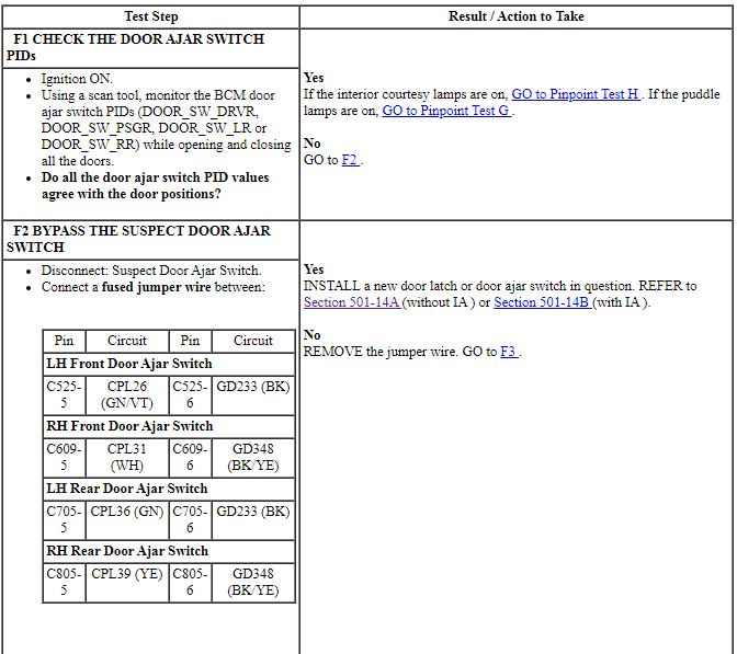
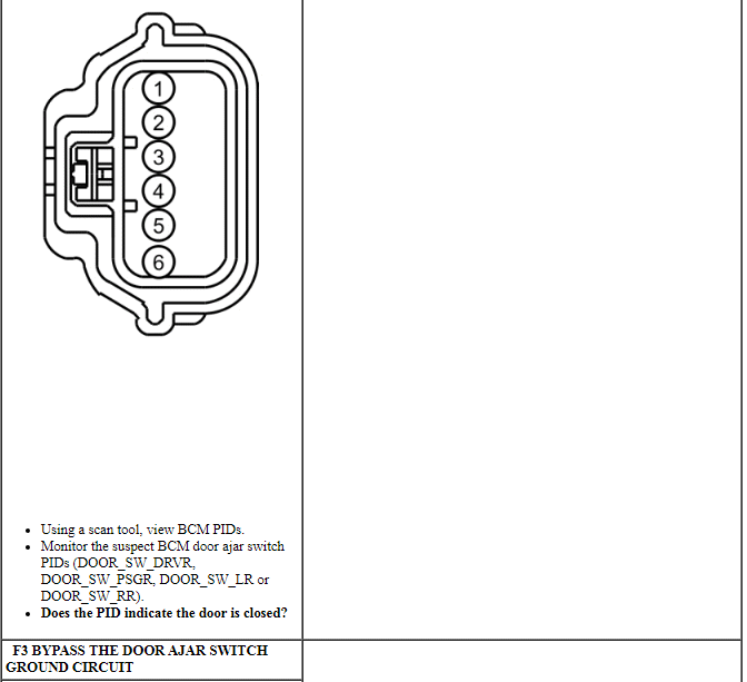
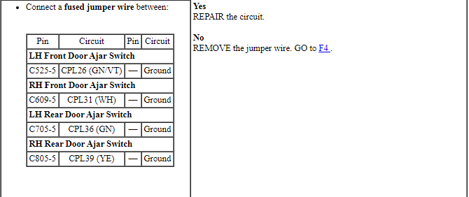
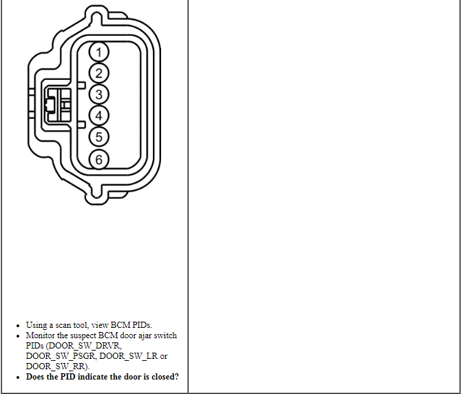
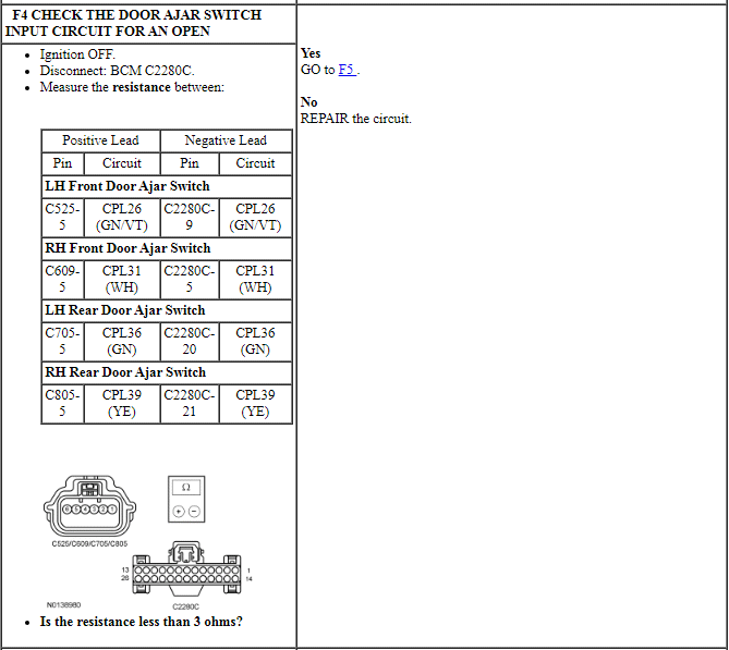
PINPOINT TEST F: ALL THE COURTESY LAMPS STAY ON CONTINUOUSLY
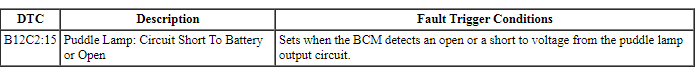
Pinpoint Test G: The Puddle Lamps Stay On Continuously
Diagnostic Overview
Diagnostics in this manual assume a certain skill level and knowledge of Ford-specific diagnostic practices. Refer to Diagnostic Methods in Section 100-00 for information about these practices.
Refer to Wiring Diagrams Cell 89, Interior Lamps for schematic and connector information.
Normal Operation and Fault Conditions
REFER to Courtesy Lamps in Interior Lighting.
DTC Fault Trigger Conditions
-
Possible Sources
- Wiring, terminals or connectors
- BCM
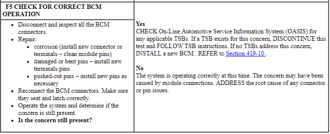
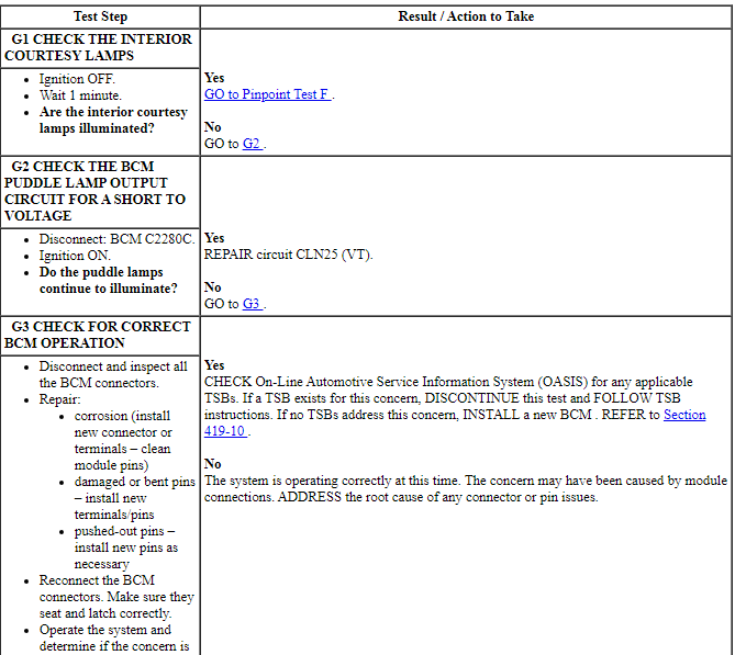
PINPOINT TEST G: THE PUDDLE LAMPS STAY ON CONTINUOUSLY

Pinpoint Test H: The Interior Courtesy Lamps Stay On Continuously
Diagnostic Overview
Diagnostics in this manual assume a certain skill level and knowledge of Ford-specific diagnostic practices. Refer to Diagnostic Methods in Section 100-00 for information about these practices.
Refer to Wiring Diagrams Cell 89, Interior Lamps for schematic and connector information.
Normal Operation and Fault Conditions
REFER to Courtesy Lamps in Interior Lighting.
DTC Fault Trigger Conditions

-
Possible Sources
- Wiring, terminals or connectors
- BCM
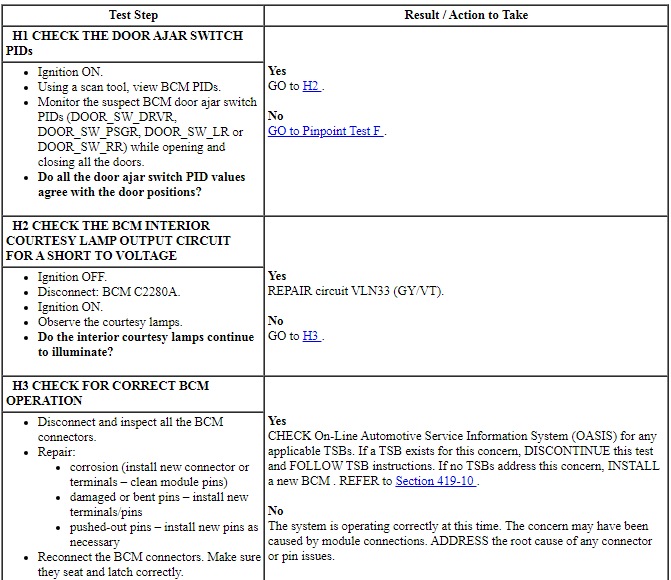
PINPOINT TEST H: THE INTERIOR COURTESY LAMPS STAY ON CONTINUOUSLY
Pinpoint Test I: All The Demand Lamps Are Inoperative
Diagnostic Overview
Diagnostics in this manual assume a certain skill level and knowledge of Ford-specific diagnostic practices. Refer to Diagnostic Methods in Section 100-00 for information about these practices.
Refer to Wiring Diagrams Cell 89, Interior Lamps for schematic and connector information.
Normal Operation and Fault Conditions
REFER to Demand Lamps in Interior Lighting.
-
Possible Sources
- BCM fuse 4 (10A)
- Wiring, terminals or connectors
- BCM
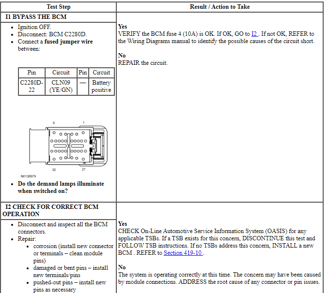
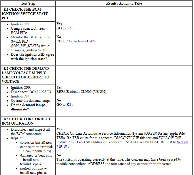
PINPOINT TEST I: ALL THE DEMAND LAMPS ARE INOPERATIVE
NOTE: Make sure the battery saver is operating correctly by checking the courtesy lamps first.
Pinpoint Test J: An Individual Demand Lamp Is Inoperative
Diagnostic Overview
Diagnostics in this manual assume a certain skill level and knowledge of Ford-specific diagnostic practices. Refer to Diagnostic Methods in Section 100-00 for information about these practices.
Refer to Wiring Diagrams Cell 89, Interior Lamps for schematic and connector information.
Normal Operation and Fault Conditions
REFER to Demand Lamps in Interior Lighting.
-
Possible Sources
- Wiring, terminals or connectors
- Demand lamp
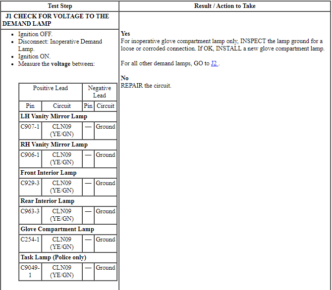
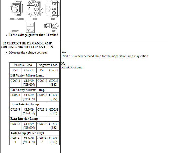
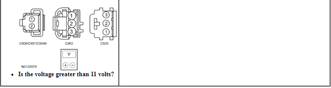
PINPOINT TEST J: AN INDIVIDUAL DEMAND LAMP IS INOPERATIVE
Pinpoint Test K: The Battery Saver Does Not Deactivate After Time-Out
Diagnostic Overview
Diagnostics in this manual assume a certain skill level and knowledge of Ford-specific diagnostic practices. Refer to Diagnostic Methods in Section 100-00 for information about these practices.
Refer to Wiring Diagrams Cell 89, Interior Lamps for schematic and connector information.
Normal Operation and Fault Conditions
REFER to Battery Saver in Interior Lighting.
-
Possible Sources
- Wiring, terminals or connectors
- BCM
PINPOINT TEST K: THE BATTERY SAVER DOES NOT DEACTIVATE AFTER TIME-OUT
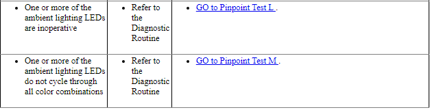
Pinpoint Test L: One Or More Of The Ambient Lighting LEDs Are Inoperative
Diagnostic Overview
Diagnostics in this manual assume a certain skill level and knowledge of Ford-specific diagnostic practices. Refer to Diagnostic Methods in Section 100-00 for information about these practices.
Refer to Wiring Diagrams Cell 89, Interior Lamps for schematic and connector information.
Normal Operation and Fault Conditions
REFER to Ambient Lighting in Interior Lighting.
Possible Sources
- Wiring, terminals or connectors
- Ambient lighting LED harness
- HVAC module
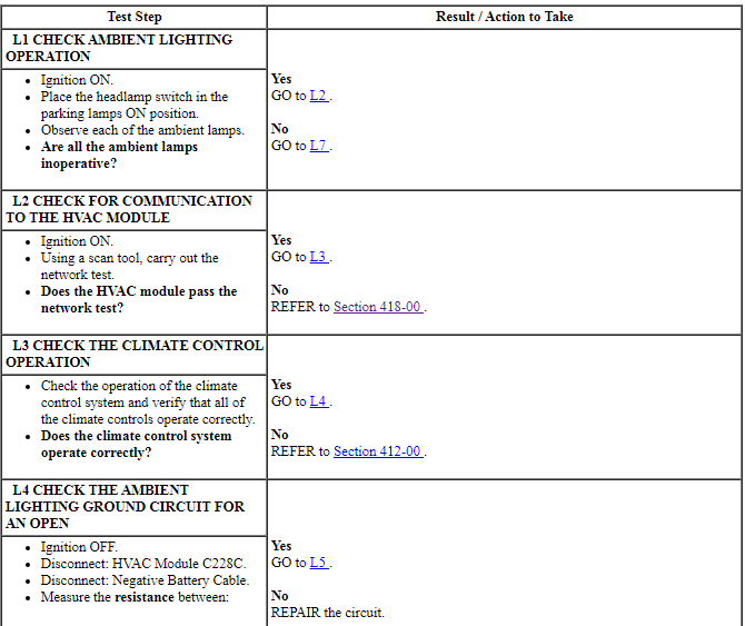
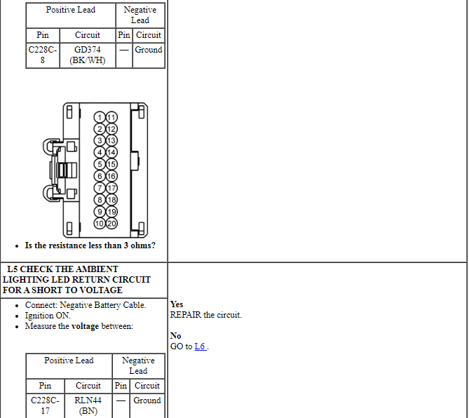
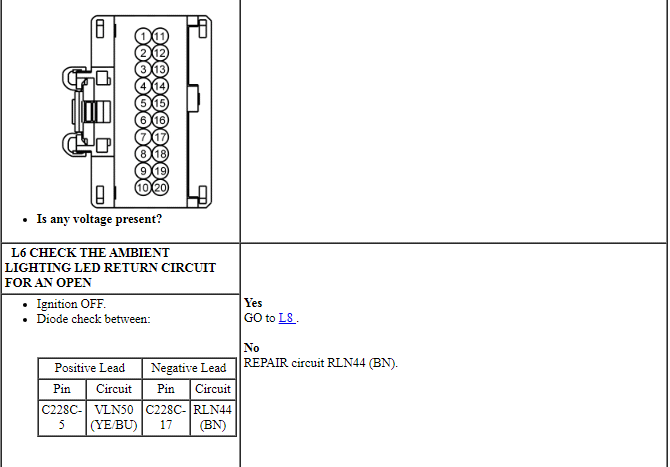
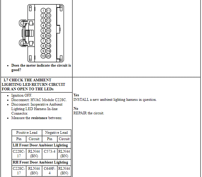
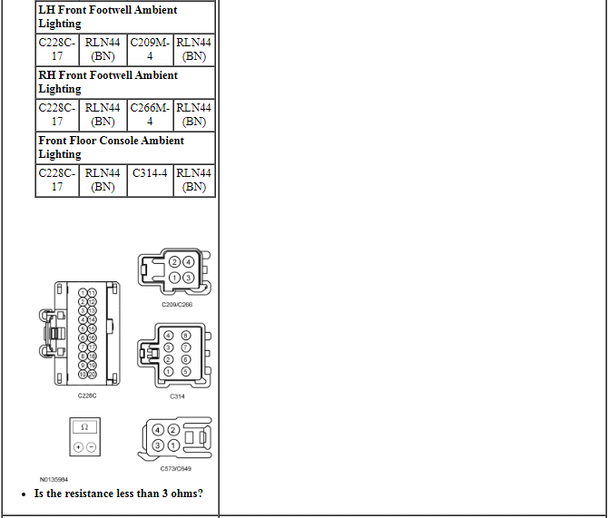
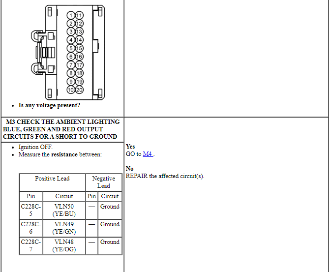
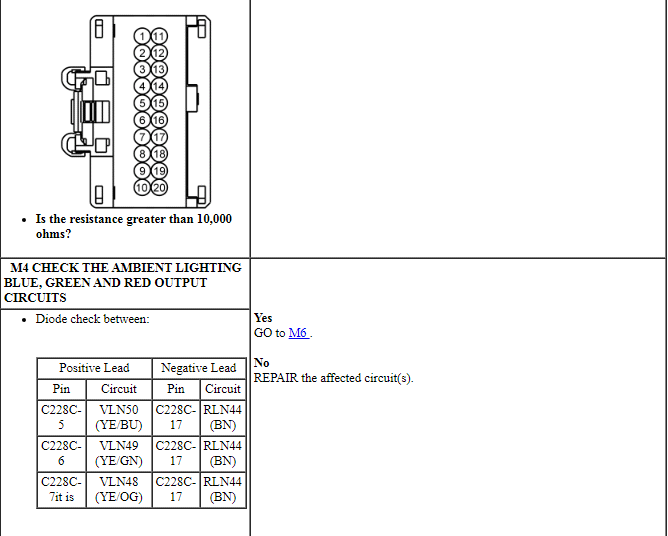
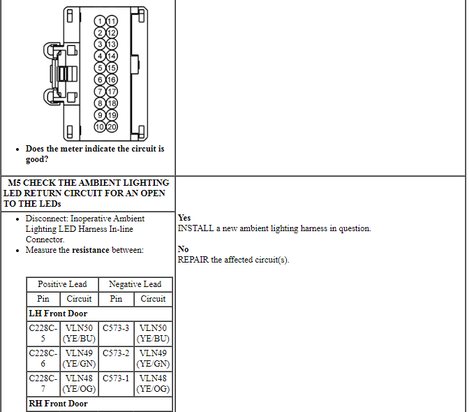
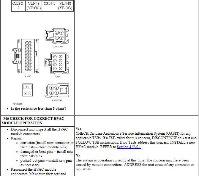
PINPOINT TEST L: ONE OR MORE OF THE AMBIENT LIGHTING LEDs ARE INOPERATIVE
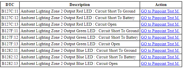
Pinpoint Test M: One Or More Of The Ambient Lighting LEDs Do Not Cycle Through All Color Combinations
Diagnostic Overview
Diagnostics in this manual assume a certain skill level and knowledge of Ford-specific diagnostic practices. Refer to Diagnostic Methods in Section 100-00 for information about these practices.
Refer to Wiring Diagrams Cell 89, Interior Lamps for schematic and connector information.
Normal Operation and Fault Conditions
REFER to Ambient Lighting in Interior Lighting.
DTC Fault Trigger Conditions
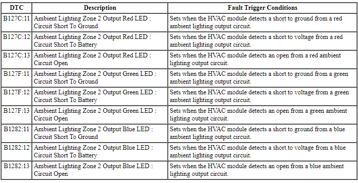
-
Possible Sources
- Wiring, terminals or connectors
- HVAC module
- Ambient lighting LED harness
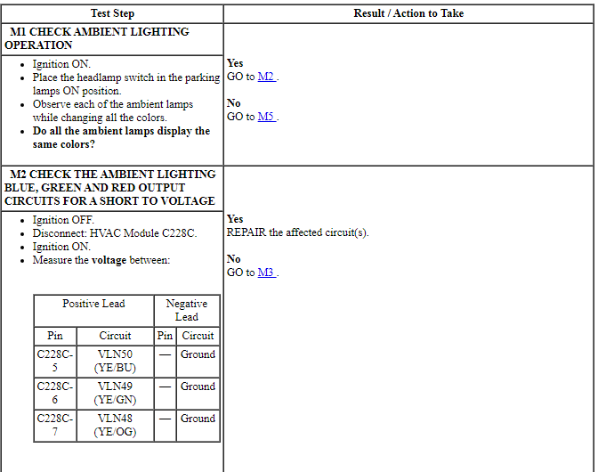
PINPOINT TEST M: ONE OR MORE OF THE AMBIENT LIGHTING LEDs DO NOT CYCLE THROUGH ALL COLOR COMBINATIONS


REMOVAL AND INSTALLATION
Interior Lamp
NOTE: Overhead console with roof opening panel shown. Other consoles are similar.
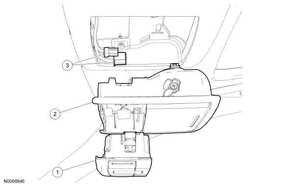
Removal and Installation
- NOTE: Do not pull down on the front of the overhead console.
Pull down on the rear of the overhead console to remove the overhead console from the retaining clips.
- Disconnect the electrical connectors.
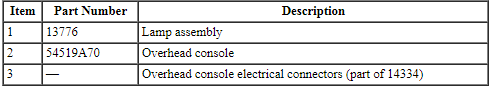
- Release the 4 retaining clips and remove the lamp assembly from the overhead console.
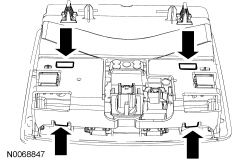
- Release the 6 retaining clips and remove the lens from the lamp
assembly.
- NOTE: The bulbs can be pushed out from the backside of the
lamp assembly.
Replace the bulb(s) as necessary.
- NOTE: The bulbs can be pushed out from the backside of the
lamp assembly.
- To install, reverse the removal procedure.
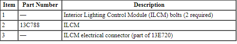
Interior Lighting Control Module (ILCM)
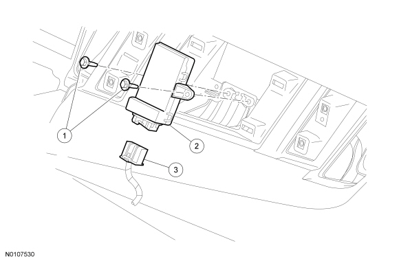
Removal and Installation
- Remove the RH instrument panel finish panel. For additional information, refer to Section 501-12.
- Remove the 2 bolts and the ILCM.
- To install, reverse the removal procedure.
 Removal and Installation
Headlamp Assembly
Removal
Remove the front bumper cover. Refer to Section 501-19.
Remove the headlamp assembly upper bolt.
To install, tighten to 3.2 Nm (28 lb-in).
Remove the h ...

Other materials:
Getting the services you need
Warranty repairs to your vehicle must be performed by an authorized
dealer. While any authorized dealer handling your vehicle line will
provide warranty service, we recommend you return to your selling
authorized dealer who wants to ensure your continued satisfaction.
Please note that certain ...
Adjusting the steering wheel
WARNING: Do not adjust the steering wheel when your vehicle
is moving.
Note: Make sure that you are sitting in the correct position. See
Sitting
in the Correct Position in the Seats chapter.
1. Unlock the steering column.
2. Adjust the steering wheel to the
desired position.
3. Lock t ...
Remote control
Integrated Keyhead Transmitters (IKTs) (If Equipped)
Use the key blade to start your
vehicle and unlock or lock the
driver door from outside your
vehicle. The transmitter portion
functions as the remote control.
Note: Your vehicle’s keys came
with a security label that provides
importa ...
