Air Conditioning (A/C) Clutch Air Gap Adjustment
- Check the A/C clutch air gap at 3 equally spaced places between the clutch plate and the A/C clutch pulley.
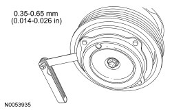
- Remove the clutch plate. Add or remove spacers between the clutch plate hub and the compressor shaft until the clearance is within specification.
Fluorescent Dye Leak Detection
Special Tool(s)
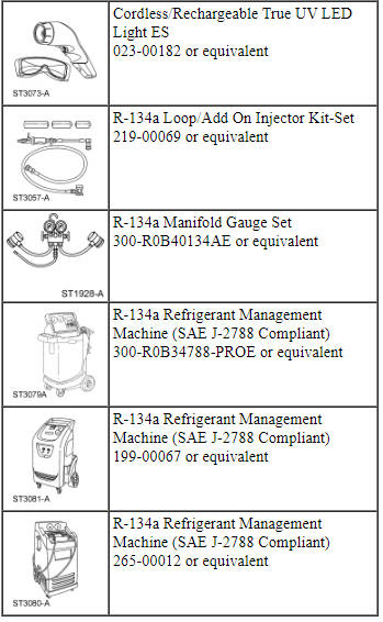
Material
Fluorescent Dye Injection Using a R-134a Refrigerant Management Machine and Dye Injector - Vehicles Requiring R-134a Addition
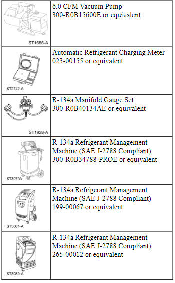
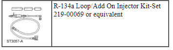
NOTE: This method of fluorescent dye injection requires the addition of R-134a from a R-134a Refrigerant Management Machine or R-134a Manifold Gauge Set hooked to an external tank to charge the dye into the refrigerant system. If adding fluorescent dye to a refrigerant system that is already fully charged, the R-134a Loop/Add On Injector Kit-Set method should be used.
NOTE: Fluorescent refrigerant system dye is added to the refrigerant system at the factory to assist in refrigerant system leak diagnosis using a Rotunda-approved UV blacklight. It is not necessary to add additional dye to the refrigerant system before diagnosing leaks, even if a significant amount of refrigerant has been removed from the system. Replacement suction accumulators and receiver/driers are shipped with a fluorescent dye "wafer" included in the desiccant bag which will dissolve after approximately 30 minutes of continued A/C operation. It is not necessary to add dye after flushing or filtering the refrigerant system because a new suction accumulator or receiver/drier is installed as part of the flushing or filtering procedure. Additional refrigerant system dye should only be added if more than 50% of the refrigerant system lubricant capacity has been lost due to a fitting separation, hose rupture or other damage.
NOTE: Before using the R-134a Loop/Add On Injector Kit-Set for the first time, refer to the manufacturer's instructions on evacuation of any non-condensable gases from the hoses.
NOTE: Only connect the dye/lubricant injector from the R-134a Loop/Add On Injector Kit-Set when fluorescent dye is to be injected. The dye/lubricant injector has a one-way check valve that will prevent refrigerant system recovery and evacuation.
- NOTE: If no R-134a pressure is present in the refrigerant system,
the system should be evacuated before carrying out the injection procedure.
For additional information, refer to Air Conditioning (A/C) System Recovery,
Evacuation and Charging in this section.
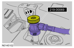
Connect a R-134a Refrigerant Management Machine or a R-134a Manifold Gauge Set to the refrigerant system service port valves.
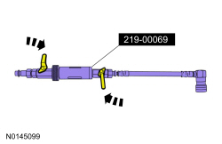
- Verify that the valves on the dye/lubricant injector from the R-134a Loop/Add On Injector Kit-Set are closed.

- Fill the R-134a fluorescent dye injector reservoir with 7 ml (0.25 oz) of fluorescent dye.

- Install the dye/lubricant injector between the low-pressure service gauge port valve and the R-134a Refrigerant Management Machine or R-134a Manifold Gauge Set.
- NOTE: Following fluorescent dye injection, the refrigerant system
should be fully charged to make sure of correct movement of the dye.
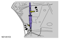
Open all valves and inject the fluorescent dye into the refrigerant system by charging the refrigerant system with the required amount of R-134a.
- When fluorescent dye injection is complete, close all valves.
- Recover the refrigerant from the dye/lubricant injector.
- Remove the dye/lubricant injector from the low-pressure service gauge port valve and the R-134a Refrigerant Management Machine or R-134a Manifold Gauge Set.
Fluorescent Dye Injection Using a R-134a Loop/Add On Injector Kit-Set - Vehicles Not Requiring R-134a Addition
NOTE: Fluorescent refrigerant system dye is added to the refrigerant system at the factory to assist in refrigerant system leak diagnosis using a Rotunda-approved UV blacklight. It is not necessary to add additional dye to the refrigerant system before diagnosing leaks, even if a significant amount of refrigerant has been removed from the system. Replacement suction accumulators and receiver/driers are shipped with a fluorescent dye "wafer" included in the desiccant bag which will dissolve after approximately 30 minutes of continued A/C operation. It is not necessary to add dye after flushing or filtering the refrigerant system because a new suction accumulator or receiver/drier is installed as part of the flushing or filtering procedure. Additional refrigerant system dye should only be added if more than 50% of the refrigerant system lubricant capacity has been lost due to a fitting separation, hose rupture or other damage.
NOTE: Before using the R-134a Loop/Add On Injector Kit-Set for the first time, refer to the equipment manufacturer's instructions on evacuation of non-condensable gases from the hoses.
NOTE: Refrigerant system pressure should be between 413-551 kPa (60-80 psi) at 24ÂşC (75ÂşF) with the engine off and cool.
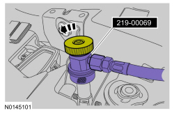
- Verify that the valves on the R-134a Loop/Add On Injector Kit-Set are closed.
- Fill the R-134a Loop/Add On Injector Kit-Set reservoir with 7 ml (0.25 oz) of fluorescent dye.

- Install the R-134a Loop/Add On Injector Kit-Set between the high-pressure and low-pressure service gauge port valves.
- NOTICE: Make sure all tools and hoses are clear of the engine
cooling fan and drive belt before starting the engine. Failure to keep tools
and hoses clear from the engine cooling fan and drive belt will result in
damage to the tools and/or vehicle.
With the A/C off, start the engine. Allow engine speed to stabilize below 1,000 rpm.
- Set the A/C to the ON position.
- Open the high-pressure service valve.
- NOTE: To prevent pressure spike/liquid slug, crack the R-134a
Loop/Add On Injector Kit-Set valves and slowly open to inject the
fluorescent dye into the refrigerant system.
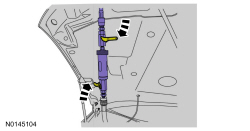
Open the R-134a Loop/Add On Injector Kit-Set valves and inject the fluorescent dye into the refrigerant system.
- Close the high-pressure service valve to allow the pressure inside the R-134a Loop/Add On Injector Kit-Set to equalize with the suction side of the refrigerant system.
- NOTE: Close the valves on the R-134a Loop/Add On Injector Kit-Set
while the A/C compressor is operating.
Close the valves on the R-134a Loop/Add On Injector Kit-Set.
- NOTE: Leave all valves on the R-134a Loop/Add On Injector Kit-Set
closed when not in use.
Disconnect the high-pressure and low-pressure service valves and remove the R-134a Loop/Add On Injector Kit-Set from the vehicle.
Fluorescent Dye Detection
NOTE: Ford Motor Company vehicles are produced with R-134a fluorescent dye installed in the refrigerant system from the factory. The location of leaks can be pinpointed by the bright yellow-green glow of the fluorescent dye under a UV lamp. Since more than one leak can exist, make sure to inspect each component, line and fitting in the refrigerant system for a leak.
NOTE: Use of dye-enhancing glasses or goggles greatly improves the detection of the dye under the UV lamp.
NOTE: Not all UV lamps will fluoresce the dye used in Ford vehicles. All Rotunda UV lamps are optimized to fluoresce the dye.
- Check for leaks using a Rotunda-approved UV lamp and dye enhancing
glasses.
- Inspect all components, lines and fittings of the refrigerant system.
- After the leak(s) is repaired, remove any traces of fluorescent dye with a general purpose oil solvent.
- Verify the repair by running the vehicle for a short period of time and rechecking the area of the leak with a Rotunda-approved UV lamp.
Electronic Leak Detection
Special Tool(s)
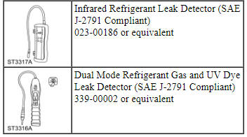
NOTE: Good ventilation is necessary in the area where electronic A/C leak testing is to be carried out. If the surrounding air is contaminated with refrigerant gas, the Heated Pentode Halogen Leak Detector will indicate this gas all the time. Odors from other chemicals such as antifreeze, diesel fuel, disc brake cleaner or other cleaning solvents can cause the same problem. Using a fan to ventilate the area to be tested before proceeding with the leak detection procedure is helpful in removing small traces of contamination from the air, but the fan should be turned off during actual testing.
NOTE: R-134a is heavier than air, and will tend to move downward from the source of the leak if present. It is possible that a leak may not be detected if the leak detector tip is held above the leaking fitting, line or component. Always be sure to thoroughly leak test below the fitting, line or component for the presence of R-134a as well as leak testing above and around.
- NOTE: The system pressure should be between 413-551 kPa (60-80
psi) at 24ÂşC (75ÂşF) with the engine off and cool. The pressure reading may
be higher if the engine is hot.
Leak test the refrigerant system using the Heated Pentode Halogen Leak Detector. Follow the instructions included with the Heated Pentode Halogen Leak Detector for handling and operation techniques.
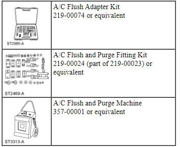
Air Conditioning (A/C) System Flushing
Special Tool(s)
Material
NOTICE: An Air Conditioning (A/C) refrigerant analyzer must be used before the recovery of any vehicle's A/C refrigerant. Failure to do so puts the shop's bulk refrigerant at risk of contamination. If the vehicle's A/C refrigerant is contaminated, refer the customer to the service facility that carried out the last A/C service. If the customer wishes to pay the additional cost, use the A/C recovery equipment that is designated for recovering contaminated A/C refrigerant. All contaminated A/C refrigerant must be disposed of as hazardous waste. For all equipment, follow the equipment manufacturer procedures and instructions.
NOTICE: Suction accumulator or receiver/drier, Thermostatic Expansion Valve (TXV) and/or evaporator core orifice, and hoses with mufflers, should be removed when flushing the Air Conditioning (A/C) system. Internal plumbing of these devices makes it impossible to correctly remove any residual-flushing agent. These components are typically discarded after A/C system contamination. Hoses without mufflers can normally be reused unless they are clogged with foreign material.
NOTICE: Only the listed A/C Flush and Purge Machine, A/C Flush and Purge Fitting Kit, A/C Flush Adapter Kit and A/C System Flushing Solvent are approved for use on Ford vehicles. No other flushing device or solvent is approved for flushing heat exchangers (Air Conditioning [A/C] condenser, A/C evaporator). Use of any other flusher or solvent may cause damage to the A/C system and the flushing unit.
- Recover the refrigerant. For additional information, refer to Air Conditioning (A/C) System Recovery, Evacuation and Charging in this section.
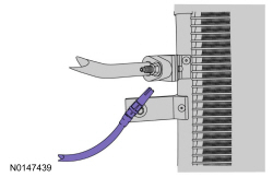
- Disconnect the refrigerant lines from the heat exchanger(s) to be flushed.
- Using the correct adapters from the A/C Flush Adapter Kit or A/C Flush and Purge Fitting Kit, connect the A/C Flush and Purge Machine to the heat exchanger to be flushed. Do not flush through the evaporator core orifice (if equipped), Thermostatic Expansion Valve (TXV) (if equipped) or hoses with mufflers. Internal plumbing and material make-up of these components make it impossible to correctly remove foreign material or residual flushing solvent.
- NOTE: Use 3.78L (1 gal) of A/C System Flushing Solvent to flush
each component for a minimum of 15 minutes. The flush solvent and flushing
unit filter are intended for use on one vehicle only.
Flush each heat exchanger and hose assembly separately for a minimum of 15 minutes.
- Apply 621-862 kPa (90-125 psi) pressurized air to the flush machine and purge each component for a minimum of 30 minutes per component being flushed. The 30-minute purge time is required to force and evaporate all residual solvent from the A/C system component. Failure to successfully remove all residual solvent within the component can result in system damage when reconnected and operated. Dispose of the used flush solvent and filter in accordance with local, state and federal regulations.
- Install a new A/C evaporator core orifice (if equipped) and/or TXV (if equipped) in any vehicle being serviced for an internal A/C compressor or desiccant failure.
- Install new refrigerant hoses with mufflers.
- Install a new suction accumulator (if equipped), receiver/drier (if equipped) or receiver/drier cartridge (if equipped) in any vehicle being serviced for an internal A/C compressor or desiccant failure.
- Reconnect the heat exchanger being serviced.
- Refer to the appropriate removal and installation procedure for remaining components being replaced.
Air Conditioning (A/C) System Recovery, Evacuation and Charging
Special Tool(s)
Material
Refrigerant System Recovery
NOTICE: An Air Conditioning (A/C) refrigerant analyzer must be used before the recovery of any vehicle's A/C refrigerant. Failure to do so puts the shop's bulk refrigerant at risk of contamination. If the vehicle's A/C refrigerant is contaminated, refer the customer to the service facility that carried out the last A/C service. If the customer wishes to pay the additional cost, use the A/C recovery equipment that is designated for recovering contaminated A/C refrigerant. All contaminated A/C refrigerant must be disposed of as hazardous waste. For all equipment, follow the equipment manufacturer procedures and instructions.
NOTE: Ford Motor Company recommends the use of R-134a refrigerant management equipment that meets the requirements of the SAE J2788 standard.
- Prior to recovering, the purity of the refrigerant must be verified. For additional information, refer to Refrigerant Identification Testing in this section.
- Connect a R-134a Refrigerant Management Machine to the low- and high-pressure service gauge port valves following the operating instructions provided by the equipment manufacturer.
- Recover the refrigerant from the system following the operating instructions provided by the equipment manufacturer. Note the amount of oil removed during the refrigerant recovery (if any). Add that same amount back into the system once repairs are complete.
- Once the R-134a Refrigerant Management Machine has recovered the refrigerant, switch OFF the power supply.
- Allow the system to set for about 2 minutes, and observe the system vacuum reading. If the vacuum is not lost, disconnect the recovery equipment.
- If the system does lose vacuum, repeat Steps 3 through 5 until the vacuum level remains stable for 2 minutes.
- Carry out the required repairs.
Refrigerant System Evacuation Using a R-134a Refrigerant Management Machine
- Connect a R-134a Refrigerant Management Machine to the low- and high-pressure service gauge port valves following the operating instructions provided by the equipment manufacturer.
- Evacuate the system until the low-pressure gauge reads at least 99.4 kPa (29.5 in-Hg) of vacuum and as close to 101.1 kPa (30 in-Hg) as possible. Continue to operate the Vacuum Pump for a minimum of 45 minutes.
- Turn OFF the Vacuum Pump. Observe the low-pressure gauge for 5 minutes to make sure that the system vacuum is held.
Refrigerant System Evacuation Using a R-134a Manifold Gauge Set and Vacuum Pump
NOTE: Leaks in refrigerant system service equipment, hoses or gauges can cause a leak in vacuum that may be misinterpreted as a problem with the vehicle's refrigerant system. It is necessary to leak-test all refrigerant system service equipment, hoses and gauges on a weekly basis to verify that no leaks are present.
- Connect the R-134a Manifold Gauge Set to the low-side and high-side service gauge port valves.
- Connect the center (yellow) hose from the R-134a Manifold Gauge Set to the suction port on the Vacuum Pump.
- Open all valves on the R-134a Manifold Gauge Set and both service gauge port valves.
- Turn on the Vacuum Pump and evacuate the system until the low-pressure gauge reads at least 99.4 kPa (29.5 in-Hg) of vacuum and as close to 101.1 kPa (30 in-Hg) as possible. Continue to operate the Vacuum Pump for a minimum of 45 minutes.
- Close the high-side and low-side valves on the R-134a Manifold Gauge Set (not the service gauge port valves) and turn OFF the Vacuum Pump.
- Observe the low-pressure gauge for 5 minutes to make sure that the system vacuum is held. If vacuum is not held for 5 minutes, leak test the system, repair the leak and evacuate the system again.
Refrigerant System Charging Using a R-134a Refrigerant Management Machine
- Lubricate the refrigerant system with the correct amount of clean PAG oil. For additional information, refer to Refrigerant Oil Adding in this section.
- Connect a R-134a Refrigerant Management Machine to the low-side and high-side service gauge port valves following the operating instructions provided by the equipment manufacturer.
- Set the refrigerant charge amount, and charge the refrigerant system following the instructions provided by the equipment manufacturer.
Refrigerant System Charging Using a R-134a Manifold Gauge Set and Automatic Refrigerant Charging Meter
NOTE: Ford Motor Company recommends use of a R-134a Refrigerant Management Machine to carry out charging of the refrigerant system. If a R-134a Refrigerant Management Machine is not available, refrigerant system charging may be accomplished using a separate Automatic Refrigerant Charging Meter and R-134a Manifold Gauge Set.
- Lubricate the refrigerant system with the correct amount of clean PAG oil. For additional information, refer to Refrigerant Oil Adding in this section.
- Assemble the R-134a Manifold Gauge Set, Automatic Refrigerant Charging Meter and R-134a supply tank following the Automatic Refrigerant Charging Meter operating instructions.
- Charge the refrigerant system following the Automatic Refrigerant Charging Meter operating instructions.
- If the refrigerant flow stops before the refrigerant charge is complete, start the engine, select MAX A/C operation and allow the refrigerant charge to complete.
Refrigerant Oil Adding
Special Tool(s)
Material
Refrigerant Oil Adding
NOTE: During normal A/C operation, oil is circulated through the system with the refrigerant, and a small amount is retained in each component. If certain components of the system are removed, some of the PAG oil will go with the component. To maintain the original total oil charge, it is necessary to compensate for the oil lost by adding oil to the system with the new part.
- Refer to the chart below for refrigerant oil adding amounts and methods of installation.
a If an excessive amount of PAG oil is lost due to a hose
rupture/separation or other damage, the total system PAG oil capacity must be
added.
b The amount specified may be used for one or multiple O-ring leak
repairs. Do not multiply the PAG oil amount by the number of O-ring leaks being
repaired.
Adding Refrigerant Oil After A/C Compressor Replacement
Service A/C compressors shipped without clutch and pulley
- Rotate the old A/C compressor shaft 6 to 8 revolutions while collecting
oil in a clean measuring device.
- If the amount of oil drained from the old A/C compressor is between 85-142 ml (3-5 fl oz), pour the same amount plus 30 ml (1 fl oz) of clean PAG Refrigerant Compressor Oil or equivalent into the new A/C compressor.
- If the amount of oil that was removed from the old A/C compressor is greater than 142 ml (5 fl oz), pour the same amount drained of clean PAG Refrigerant Compressor Oil or equivalent into the new A/C compressor.
- If the amount of oil that was removed from the old A/C compressor is less than 85 ml (3 fl oz), pour 85 ml (3 fl oz) of clean PAG Refrigerant Compressor Oil or equivalent into the new A/C compressor.
Service A/C compressors shipped with clutch and pulley
- Rotate the old A/C compressor shaft 6 to 8 revolutions while collecting
oil in a clean measuring device.
- If the amount of oil drained from the old A/C compressor is less than 89 ml (3 fl oz), remove 118 ml (4 fl oz) from the new A/C compressor.
- If the amount of oil drained from the old A/C compressor is 89 ml (3 fl oz), remove 89 ml (3 fl oz) from the new A/C compressor.
- If the amount of oil drained from the old A/C compressor is 118 ml (4 fl oz), remove 59 ml (2 fl oz) from the new A/C compressor.
- If the amount of oil drained from the old A/C compressor is 148 ml (5 fl oz), remove 29 ml (1 fl oz) from the new A/C compressor.
- If the amount of oil drained from the old A/C compressor is greater than 148 ml (5 fl oz), remove 0 ml (0 fl oz) from the new A/C compressor.
Adding Refrigerant Oil After New Suction Accumulator or Receiver/Drier Replacement
NOTE: This refrigerant oil adding method is to be used when a new suction accumulator or receiver drier only has been installed. If a new A/C compressor and evaporator core orifice or Thermostatic Expansion Valve (TXV) have also been installed due to system contamination, refer to the appropriate heading.
- Drill one 12.7 mm (1/2 in) hole in the old suction accumulator or receiver/drier cylinder and drain the oil into a clean measuring cup.
- Add the same quantity of new PAG oil, plus the amount collected during refrigerant recovery and 60 ml (2 fl oz).
Adding Refrigerant Oil After Multiple Component Replacement After A/C System Contamination
NOTE: This refrigerant oil adding method is to be used when a new A/C compressor, suction accumulator or receiver drier and evaporator core orifice or TXV have been installed due to system contamination and the A/C system has been flushed.
- If the new A/C compressor is shipped with a new clutch and pulley already installed, remove the shipping caps and rotate the new A/C compressor shaft 6 to 8 revolutions while collecting the oil in a clean measuring cup.
- Add 60 ml (2 fl oz) directly to the new A/C compressor suction port.
- Inject the total vehicle PAG oil capacity minus 60 ml (2 fl oz) to the low-side service port during system charging. For the total PAG oil capacity specification, refer to the Specifications table in this section.
Oil Injection Using a Dye/Lubricant Injector
NOTE: If fluorescent leak detection dye is also to be added during A/C charging, the dye may be added to the dye/lubricant injector, from the R-134a Loop/Add On Injector Kit-Set, along with the PAG oil.
- Evacuate the refrigerant system. For additional information, refer to Air Conditioning (A/C) System Recovery, Evacuation and Charging in this section.
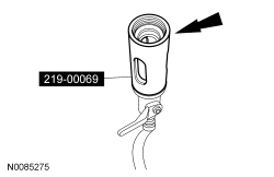
- Assemble the dye/lubricant injector and the correct adapters from the R-134a Loop/Add On Injector Kit-Set to match the amount of refrigerant compressor oil to be injected.
- Verify that all the valves on the dye/lubricant injector are closed.
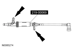
- Fill the dye/lubricant injector with the correct amount of clean, new PAG oil.
- Install the dye/lubricant injector between the low-side service gauge port valve and the refrigerant service station or manifold gauge set.
- Open all valves and charge the refrigerant system. For additional information, refer to Air Conditioning (A/C) System Recovery, Evacuation and Charging in this section.
Refrigerant Identification Testing
Special Tool(s)
Refrigerant Identification
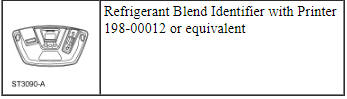
- NOTE: A Refrigerant Blend Identifier with Printer must be used to
identify gas samples taken directly from the refrigeration system or storage
containers prior to recovering or charging the refrigerant system.
Follow the instructions included with the Refrigerant Blend Identifier with Printer to obtain the sample for testing.
- The Refrigerant Blend Identifier with Printer will display one of the
following:
- If the purity level of R-134a is 98% or greater by weight, the green PASS LED will light. The weight concentrations of R-134a, R-12, R-22, hydrocarbons and air will be displayed on the digital display.
- If refrigerant R-134a does not meet the 98% purity level, the red FAIL LED will light and an alarm will sound alerting the user of potential hazards. The weight concentrations of R-134a, R-12, R-22 and hydrocarbons will be displayed on the digital display.
- If hydrocarbon concentrations are 2% or greater by weight, the red FAIL LED will light, "Hydrocarbon High" will be displayed on the digital display, and an alarm will sound alerting the user of potential hazards. The weight concentrations of R-134a, R-12, R-22 and hydrocarbons will also be displayed on the digital display.
- The percentage of air contained in the sample will be displayed if the R-134a content is 98% or greater. The Refrigerant Blend Identifier with Printer eliminates the effect of air when determining the refrigerant sample content because air is not considered a contaminant, although air can affect A/C system performance. When the Refrigerant Blend Identifier with Printer has determined that a refrigerant source is pure (R-134a is 98% or greater by weight) and air concentration levels are 2% or greater by weight, it will prompt the user if an air purge is desired.
- If contaminated refrigerant is detected, repeat the refrigerant identification test to verify that the refrigerant is indeed contaminated.
Contaminated Refrigerant Handling
NOTICE: If contaminated refrigerant is detected, DO NOT recover the refrigerant into R-134a recovery/recycling equipment. Recovery of contaminated refrigerant will contaminate the recovered refrigerant supply and may damage the recovery/recycling equipment.
NOTE: A new suction accumulator or receiver/drier must be installed as directed by the A/C system flushing procedure.
- Recover the contaminated refrigerant using suitable recovery-only
equipment designed for capturing and storing contaminated refrigerant only.
- If this equipment is not available, contact an A/C service facility in the area with the correct equipment to carry out this service.
- Determine and correct the cause of the customer's initial concern.
- Flush the A/C system.
- Dispose of the contaminated refrigerant in accordance with all federal, state and local regulations.
Air Conditioning (A/C) Odor Treatment
Special Tool(s)
Material
WARNING: Carry out this procedure in a well-ventilated area with all vehicle windows and doors opened. Carefully read cautionary information on product label. For emergency medical information, seek medical advice. On Ford/Motorcraft products in the USA or Canada call: 1-800-959-3673. For additional information, consult the product Material Safety Data Sheet (MSDS), if available. Failure to follow these instructions may result in serious personal injury.
NOTE: There are typically 4 types of objectionable odors found in a vehicle:
- Chemical odors
- Environmental odors
- Human and other interior-generated odors
- Microbiological odors
Before determining that A/C odor treatment is required, the source and the circumstances under which the odor occurs must be determined.
NOTE: Chemical odors are usually constant regardless of the climate control system setting although they may be enhanced by A/C operation. Most chemical odors are caused by fluid leaks or incorrectly cured adhesives. Chemical odors can be eliminated by repairing the leaking component and removing any residue.
NOTE: Environmental odors usually occur for a short time and diminish after the vehicle passes through the affected area. These odors are typically only detected when the vehicle windows are open, or when the climate control system is operating in a mode that allows for fresh air. Environmental odors cannot be eliminated because they are external in source, but they may be minimized by switching to a climate control setting that uses recirculated air.
NOTE: Human and other interior-generated odors occur while the source is present and may linger for a short time after. These odors may be more noticeable during A/C operation. Human odors may be eliminated by removing the source and cleaning the affected area.
NOTE: Microbiological odors, if in the A/C system, usually last for about 30 seconds after the system is turned on. They will be detected while the A/C is turned on and using either outside or recirculated air. Microbiological odors that occur in areas other than the A/C system (for example, water in doors or wet carpeting) may last indefinitely and will be more intense when recirculated air is used. Microbiological odors will not be present at temperatures at or below 10ÂşC (50ÂşF).
Microbiological odors can be eliminated by removing the source and treating the affected area. Standing water must be allowed to drain and dry out. A/C systems may be treated by using A/C Cooling Coil Coating as described in the service procedure below.
Microbiological odors result from microbial growth supported by warm temperatures and moisture. Microbiological odors are described as musty/mildew type smells and may occur on/in:
- foam seals
- rubber seals
- adhesives
- standing water
- water soaked carpet/trim
- Identify the type of odor present in the vehicle. Do not proceed with A/C odor treatment if the odor source is found to be outside of the A/C system. Refer to the following chart for examples.
- Identify the source of the odor.
- Check the evaporator core drain tube for restriction.
- Check the passenger and driver side carpet for moisture. If moisture is found, A/C odor treatment is not necessary. Diagnose for a water leak as needed.
- Check the blower motor and blower motor cover (if equipped) for moisture resulting from water bypassing the cowl baffling system. If moisture is found, A/C odor treatment is not necessary. Diagnose for a water leak as needed.
- Check the cowl top panel and air inlet screen for standing water or foreign material. If possible, remove any standing water and clean the air inlet screen using a wet/dry vacuum.
- Open all vehicle windows and doors.
- Make sure that the A/C is off.
- Set the following.
- Select PANEL mode (A/C off).
- Adjust the temperature setting to full warm.
- Adjust the blower motor speed to HI.
- Run the engine for 25 minutes to dry out the A/C system.
- Turn the ignition OFF.
- Remove the blower motor.
- NOTE: Blower motor speed controls that are mounted outside of the
evaporator core housing and not exposed to the blower motor airflow do not
need to be removed.
Remove the blower motor resistor (if equipped) or blower motor speed control (if equipped and exposed to the inside of the evaporator core housing).
- NOTICE: To avoid damage to the vehicle interior, do not spill
or spray this product on any interior surface.
Add one full bottle of A/C Cooling Coil Coating to the Flexible Applicator Tool.
- Insert the nozzle into the evaporator housing and direct the spray toward the evaporator core face. Spray the entire evaporator core face until empty.
- Install the blower motor and blower motor resistor (if equipped) or blower motor speed control (if equipped).
- Repeat Steps 4 through 6 to cure the evaporator core coating.
 Diagnosis and Testing
Climate Control System
Special Tool(s)
Principles of Operation
For additional refrigerant system and component information, refer to Section
412-01.
Climate Control System Network Communicatio ...
 Climate Control
...
Other materials:
Satellite radio information
Satellite Radio Channels
Sirius broadcasts a variety of music, news, sports, weather, traffic and
entertainment satellite radio channels. For more information and a
complete list of Sirius satellite radio channels, visit www.siriusxm.com in
the United States, www.sirius.ca in Canada, or call Sir ...
Removal and Installation
Antenna - Satellite Radio
Removal and Installation
NOTE: This procedure applies to both the stand-alone satellite radio
antenna and the combination satellite radio/Global Positioning System (GPS)
antenna.
Lower the headliner. For additional information, refer to Section
501-05.
...
Sensing system
WARNING: To help avoid personal injury, please read and
understand the limitations of the system as contained in this
section. Sensing is only an aid for some (generally large and fixed)
objects when moving in reverse on a flat surface at parking speeds.
Traffic control systems, inclement weat ...
